CONTENTS:
What exactly counts as a rotary engine? As the collection expands, new galleries have been added to the museum building to aid with classification and organisation. Several types of engine that were originally on display on this page have now been moved to their own galleries:
In a convulsive effort to make the Rotary Steam Engine gallery a bit more organised, I have rearranged the engines into chronological order. Some sections have been split off into separate pages to make the downloading less onerous and there may be more of that in the future. Now read on...
Early in the history of the steam engine, many inventors felt that conventional construction, with piston, connecting rod and crank was unduly space-consuming, and also far from perfect when it came to generating unbalanced reciprocating forces. A rotary steam engine, that used the expansion of steam to generate shaft rotation directly, promised to be far more compact, exactly as the Wankel rotary engine promised to revolutionise the internal-combustion engine. Some versions claimed to give a uniform torque so that a flywheel was not required; but this is by no means inherent in a rotary engine and many of the designs shown here have conspicuously large flywheels.
The truth, however, is that rotary steam engines were a snare and delusion for the unwary inventor that came second only to the perpetual motion machine, and a good number of lives must have been blighted by the pursuit of what looked easy, but proved unattainable in a practical form. It is notable how contemptuous commentators writing in the mid-19th century were about these machines and their advocates. It was obviously considered that since a practical engine had not appeared in some hundred years, the idea was proven to be unsound, and the contemporary inventors who attempted to get rid of cranks, were... cranks.
One of the few authors to write in any depth on rotary steam engines was the famous Franz Reuleaux, in his book "The Kinematics of Machinery", which was published in English in 1876, and is considered the foundation of scientific kinematics. He deals with many rotary steam engine designs from a strictly theoretical standpoint; the phrase "Reuleaux says..." will be found scattered throughout these pages, usually followed by pitiless condemnation of the engine in question.
Unless otherwise stated, none of the engines here got anywhere.
A MATTER OF DEFINITION.
What we are NOT dealing with here:
- Radial engines. The radial internal combustion engine, mostly used in aeroplanes, has its cylinders arranged in a circle but it uses conventional pistons and connecting rods. Radial engines were also used in a few other applications, such as torpedo motors powered by compressed air. A notable example was The Brotherhood Engine.
- Rotary engines, as used in aeroplanes. These are a variation on the radial engine. In the rotary version, the engine is fixed to the propellor, and this assembly rotates around a crankshaft fixed to the aeroplane. There were some advantages to this apparently daft arrangement (eg plenty of air-cooling as the cylinders are rotating) but some serious problems too, and the rotary aircraft engine fell out of use after World War 1.
- Rotary internal combustion engines, such as the Wankel. I now have a page on rotary IC engines.
- Rotative steam engines. People sometimes talk about Watt et al inventing the rotary steam engine when they actually mean the rotative engine, ie one that gives its output via a rotating shaft. (as opposed to the earliest steam engines, which drove mine pumps entirely by reciprocating action, with no crank or flywheel involved)
To add to the confusion Watt did patent not one but two genuine rotary steam engines. (neither of which were worth a light, it must be said) See below.
- Steam turbines. Not rotary steam engines within the definition used here, as they do not work by steam expanding in a closed space.
EARLY ROTARY STEAM ENGINES: 1765-1839.
Leaving aside Hero's Aeloipile, which is usually considered to be a kind of steam turbine, the earliest rotary steam engine I have so far discovered is that of a certain Mr James Watt. His patent of 1769 refers to applying a separate condenser to rotary steam engines. Nothing further was done then, but in 1774 a steam wheel was made and set to work at Boulton's factory in Soho, Birmingham. When the bill for extending Watt's patent was before parliament, Joseph Harrison and Samuel Garbett testified that they had seen it working, and it was 6 feet in diameter and weighed upwards of a ton.
From Dickson.
Earlier references are often made to Ramelli, (1588) who proposed a vane-type rotary water pump, and Pappenheim, who proposed a rotary gear type pump, (1636) like those widely used to supply lubricating oil in car engines. Neither of these proposals contained any suggestion that the device could be used as a steam engine; however these basic topologies reappeared again and again in the unhappy history of rotary engines.
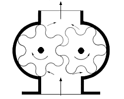 | .
| Left: The Pappenheim gear pump.
It is uncertain whether "Pappenheim" is the name of the inventor or of the town where it originated.
|
THE JAMES WATT ENGINE: 1765
 | .
| Left: James Watt's rotary of 1765
Modus operandi: f is the steam inlet, and q the steam exhaust.
c is the rotating piston, and as it turns the hinged valve d is knocked into the recess e, closing inlet f. Valve d then falls open to let in steam again.
It all sounds very doubtful, and R S Burn thought so too, remarking: "From the force with which the piston strikes the valve d, the machine rapidly falls into disrepair"
And there is also the little matter of making it steam-tight. No chance.
From "The Steam Engine- Its History & Mechanism" by Robert Scott Burn
|
This looks very much like the "hinged abutment" design of The James Engine, of 135 years later, which proves that what goes around comes around, at least as far as rotary engines are concerned. Reinvention is a recurring theme in the world of rotary engines.
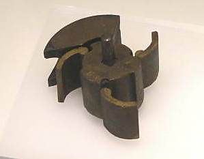 | .
| Left: James Watt's three-vane rotary of 1782
I understand that the Science Museum (London) has inconspicuously displayed a 3-vane rotor, about 6 inches across, labelled as an experimental part by Watt in 1782. This appears to be a development of the single-vane engine of 1765, and demonstrates that Watt had a long-term interest in rotary engines.
The part at the rear is the sector-shaped block visible in the animation below. The channel cut in it for steam exhaust is visible.
|
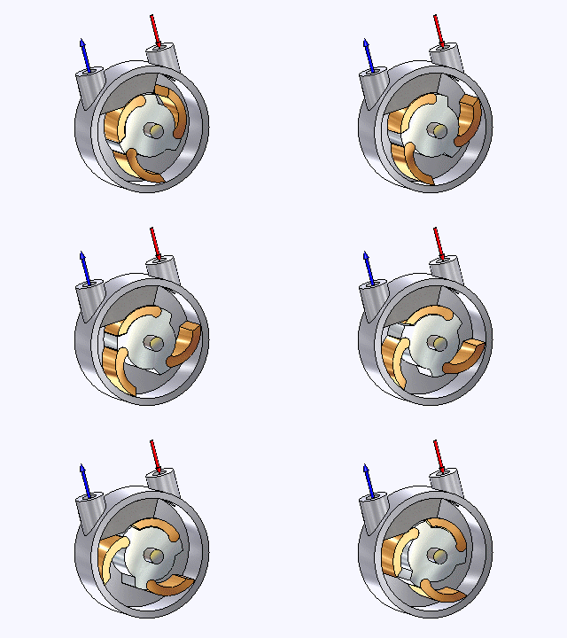 | .
| Left: James Watt's three-vane rotary of 1782
This fine animation by Bill Todd shows how the engine was supposed to work. Note that the three vanes or flaps swing out under the pressure of the incoming steam and strike the casing with a mighty blow. No doubt this machine rapidly fell into disrepair as well; it would certainly have been hideously noisy.
Info and animation by Bill Todd
|
These designs are referred to in one of Watt's letters dated 1782, where he states that small-scale models were made of brass in 1765-66, but that little if any experimental work was carried out with them. Which, with the wisdom of hindsight, was just the right approach.
THE COOKE ENGINE: 1787

|
| Left: The Cooke Rotary Engine: 1787.
This engine, with its interesting semi-circular format, is the earliest rotary steam engine known, apart from those of Watt above. Patented by James Cooke in 1787.
b is the steam inlet from the boiler, and a is the exhaust to the condenser. As the wheel rotates the flaps c fall forward by gravity and are then kept in place by the steam pressure pushing the wheel round. The connecting rod d is driven by a crank on the engine axle and works the condenser air-pump.
The wheel is only enclosed up to the line f, and one can only guess what sealing system was planned to keep the long line contacts steam-tight.
Elijah Galloway says: "The construction of this machine we need hardly say would be impractical." and one can hardly disagree.
The original drawing and description are found in Transactions of The Royal Irish Academy for 1787.
From The History and Progress of the Steam Engine by Elijah Galloway & Luke Hebert, London 1830.
|
THE BRAMAH & DICKENSON ENGINE: 1790
|
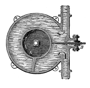
| Left: The Bramah & Dickenson Rotary Engine: 1790.
There is a rotating inner cylinder with one vane or piston attached. Mr Ewbank says: "A butment BB slides backwards and forward in a stuffing box and is so arranged (by a cam or some other contrivance connected to the axle of the small cylinder on the outside of the case) that it can be pushed into the interior as in the figure, and at the proper time be drawn back to afford passage of the piston" Bramah and Dickenson adopted this configuration in 1790 as steam engine and also a pump.
This sounds very dubious. the 'butment' will have to move very snappily to clear the vane, hopefully with some safety margin if a nasty crash is to be avoided. But that safety margin implies a direct passage for steam between the inlet and exhaust, which is hardly going to make for economical operation. Later machines such as the Galloway engine, adopted the same unpromising approach.
From "Hydraulic & Other Machines For Raising Water" Thomas Ewbank, 1850
|
Bramah was a versatile engineer who patented his hydraulic press in 1796, a screw propellor in 1785, and a flush toilet in 1778. His first rotary engine patent was in 1785, for a machine very like that of Watt's 1782 patent, with a hinged abutment that was to have been closed by a weight, which does not sound like recipe for high-speed operation.
THE RUMSEY ENGINE: 1791
James Rumsey (1743-1792) was an American mechanical engineer who is best known for exhibiting a boat propelled by machinery in 1787 on the Potomac River at Shepherdstown, West Virginia. A steam-driven pump ejected a stream of water from the rear of the boat, propelling it forwards. After moving to England in 1788, Rumsey took out four patents there before his death in 1792. These mostly covered various machines concerned with hydrostatics and water power, but the 1791 patent included the rotary steam engine shown below.
 |
| Left: The Rumsey Rotary Engine: 1791.
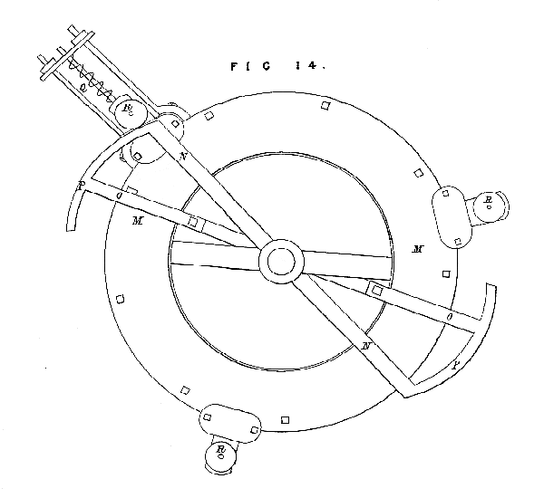
This engine works on the sliding-door principle in the same way as the Bramah & Dickenson engine shown above. In this case there are three spring-loaded doors, actuated by an external skeleton cam operating on three rollers.
In this view of the outside, the cam is composed of parts M,N,O,P, and it acts on the rollers R. At first, something seems to be awry with the drawing, for it appears the rotation would be stopped by what looks like a cross-member; this however is probably the radial steam passage marked D in the drawing below, and so rotates with the skeleton cam.
Details sent to me by Nick Blanton of the Rumseian Society. See jamesrumsey.org.
|
 |
| Left: The Rumsey Rotary Engine: 1791.
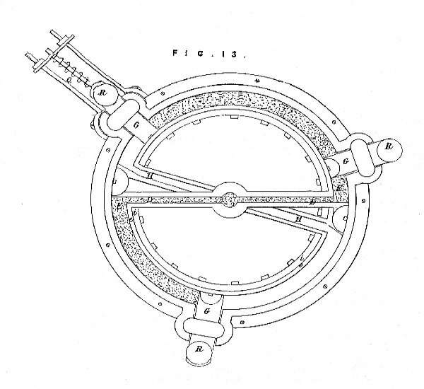
Here are the internal workings. Steam enters at the center and passes outwards along the radial arms D. It presses against the sliding doors G and causes the central part of the engine to rotate in a clockwise direction.
There appear to be two cylindrical rollers, half-hidden by the outer casing, between arms D and H, and these presumably act on the doors G directly, pushing them out of the way. If this is the case, then the external cam system is apparently redundant; perhaps it was intended as an auxiliary method of withdrawing the doors, so the mechanical impact would be lessened.
When the doors G withdraw, the steam is allowed to escape inwards along radial arms H, and to exhaust via the central axle.
Details sent to me by Nick Blanton of the Rumseian Society.
|
 |
| Left: The Rumsey Rotary Engine: 1791.
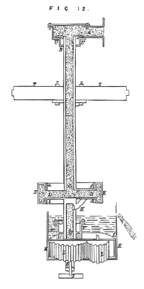
This shows a complete installation of the engine. The engine itself is the structure at D and E, with D being the radial inlet arms as shown in the drawing above.
Steam from the boiler enters the hollow vertical shaft at the top, via a rotating gland B. Exhaust steam leaves the engine at H, and proceeds downwards to the condenser through another hollow rotating shaft, which drives a gear-type pump L,L which extracts air.
Several thing are mysterious about this drawing. Why is the vertical inlet shaft so long? Where is the power taken off? Is the structure T,T a beam carrying a bearing, or a massive flywheel?
It is not currently known if this engine was ever built and tested. My guess is no.
Details sent to me by Nick Blanton of the Rumseian Society.
|
THE CARTWRIGHT ENGINE: 1797 PATENT
|
| Left: The Cartwright Rotary Engine: 1797.
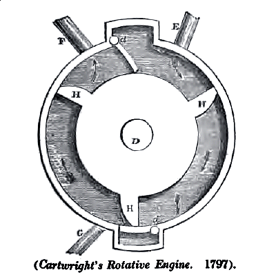
In 1797 Mr Edmund Cartwright patented an engine which was similiar to Watt's 'abutment' engine, only with two flaps and three 'pistons' formed on the rotating cylinder.
Cartwright (I think it was the same Cartwright) also came up with a conventional piston engine that ran on alcohol vapour; an alcohol engine.
Pipe E is the steam inlet and F is the exhaust. The purpose of C is unknown; possibly it was a drain for condensate.
From The History and Progress of the Steam Engine by Elijah Galloway & Luke Hebert, London 1830.
|
THE HORNBLOWER ENGINE: 1798 PATENT
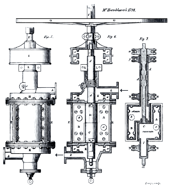
|
Above: The Hornblower Rotary Engine: 1798.
Image from A Treatise on The Steam Engine in Its Application to Mines,Mills, steam navigation and Railways by the Artizan Society, ed John Bourne, pub 1853 Longmans
|
The first Hornblower rotary engine (for there were two) was the most complex design so far. Jonathan Carter Hornblower (born Chacewater, July 5, 1753; died Penryn, February 23, 1815) was a Cornish pioneer of steam power, the son of Jonathan Hornblower and brother of Jabez Carter Hornblower, two other steam pioneers.
He developed a compound steam engine in 1781 but was prevented from pursuing it by patent litigation with Boulton & Watt over the use of a separate condenser. His rotary engines also ran into trouble with Watt's patents on the subject. In other developments in steam technology he was more successful and he died a rich man.
(I strongly suspect that this family was the inspiration for the name Horatio Hornblower, the sea-faring hero of the novels by C. S. Forester; his exploits were based on Lord Cochrane, who combined an extraordinary naval career with an enthusiasm for rotary steam engines)
|
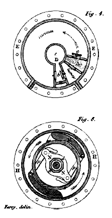
| Left: The Hornblower Rotary Engine: 1798.
The engine used two rotating rectangular vanes A,B which were fixed to coaxial shafts, and rotated semi-independently. There are two steam valves a, and two exhaust valves b, in the surfaces of the vanes. In Fig 6 above, h is the steam inlet and k the exhaust.
Each shaft carried a one-way clutch, a sort of frictional ratchet, which allowed them to rotate forwards but not backwards; see MM in Fig 8 to the left. These clutches worked in the channels ww just above and below the cylinder.
When steam was introduced between the two vanes, as shown in Fig 4 at left, it tended to push them apart, but only one of them could move. When the moving vane rotated so it came up behind the stationary one, their roles were reversed by the action of the valves, and the vane which had been stationary set off around the cylinder, leaving its mate behind. Neither the drawing or Bournes' description makes it clear how this reversal of roles was brought about.
Similar one-way clutches worked inside the two channels xx,yy in the housing I shown at the top of Fig 6, below the flywheel G. This housing was rotated by the clutch of whichever of the coaxial shafts was moving, and was fixed to the output shaft and a heavy flywheel, demanded by the stop-start action of this engine.
From A Treatise on The Steam Engine in Its Application to Mines,Mills, steam navigation and Railways by the Artizan Society, ed John Bourne, pub 1853 Longmans
|
A patent was taken out, but so far I have not discovered if this engine was built and tested. Elijah Galloway was of the opinion that it would soon destroy itself as the two vanes whacked into each other, and no doubt he was right. The clutch system also looks like a major snag as it relied on friction to work, so a little misplaced grease would soon mess up its operation.
A simplified clutch system was propsed by Carter in 1821.
The second Hornblower will be added to this page when details of it have been unearthed.
THE MURDOCH ENGINE: 1799

|
| Left: The Murdoch Rotary Engine: 1799.
William Murdoch, (or Murdock) one of Watt's co-workers, adapted Pappenheim's gear pump to create a rotary piston steam engine, using wooden packing at the tips of the cog teeth. Excessive steam leakage discouraged further development.
An engine of this type was installed in 1802 at Boulton & Watt's Soho factory to drive machines in Murdoch's workshop. It was supposed to produce 1/2 HP, but "It proved not to be capable of meeting any useful purpose." (Norbye)
(note that this Soho factory was in Birmingham, not the red light district in London)
Steam enters through pipe B and exits into the condenser at the bottom. There seems to be a conventional reciprocating piston to the right of the structure marked H, and this is almost certainly the condenser air pump.
Image from "A Descriptive History of the Steam Engine" by Robert Stuart, p174. Second edition, 1824.
|
John Bourne on Murdoch's Engine:
"There is much friction in this kind of engine, much leakage, and but a small power realised in proportion to the size of the machine. The same scheme is proposed for raising water in Leopold's Theatrum Machinarum of 1720, where it is called the
machina pappenheimiana..."
From A Treatise on The Steam Engine in Its Application to Mines,Mills, steam navigation and Railways by the Artizan Society, ed John Bourne, pub 1853 Longmans
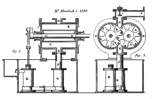
|
|
Above: The Murdoch Rotary Engine: 1799.
Two views of the Murdoch engine. H is the steam inlet and K the exhaust. Q is the condenser and R is the air-pump, driven by crank Z on one of the engine output shafts. What, no rotary air-pump?
From A Treatise on The Steam Engine in Its Application to Mines,Mills, steam navigation and Railways by the Artizan Society, ed John Bourne, pub 1853 Longmans
|
THE FLINT ENGINE: 1805 PATENT
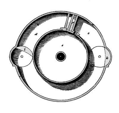
|
| Left: The Flint Rotary Engine: 1805.
Andrew Flint took out a patent for his engine in 1805.
The rotor e has a fixed vane or piston p which sweeps round under steam pressure. There are two lunate (moon-shaped) valves at i and k that swivel round to allow the passage of the vane. These valves are driven by external linkages as shown below.
Steam enters via port h and leaves through port g, which unfortunately appears to be missing from this drawing.
From "A Descriptive History of the Steam Engine" by Robert Stuart, p174. Second edition, 1824. This remarkable book is a detailed and highly competent account of the early history of steam power, describing inventors and engines I have seen nowhere else; it is also very readable. My copy cost me £150.
|
|
| Left: The Flint Rotary Engine: side view.
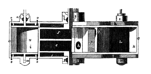
The rotor is divided in two by a partition; steam enters and leaves via the hollow shaft.
Note the threaded bushes at y, n and 2 for compressing the packing around the hollow main shaft and the two valve spindles. This is the easy part of the sealing problem.
From "A Descriptive History of the Steam Engine" by Robert Stuart
|
|
| Left: The Flint Rotary Engine valvegear.
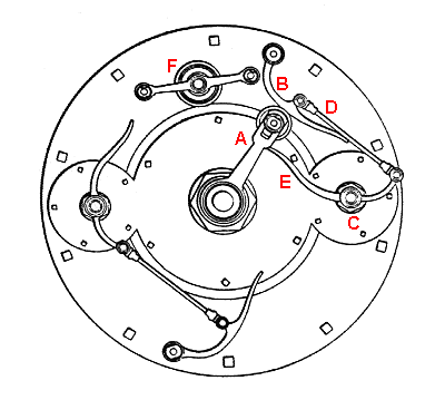
As the A arm rotates, the roller at the end of it hits lever B, operating the valve spindle C by link D, and swiveling the solid section of the valve out of the way of the approaching vane. Having rotated further, it hits lever E which is directly connected to the valve spindle, swiveling it back to form a "seal" between the outer casing and the rotor; the chances of making this arrangement steam-tight are poor.
Having rotated through 180 degrees, it repeats these operations on the valve on the other side of the casing.
From "Norbye"
|
This valve system, with bits of metal whacking other bits of metal, may appear crude and deeply unsuitable for high-speed operation, but you have to remember that in 1805 steam engines moved at a slow and ponderous speed. Possibly this design was intended to be big and rotate slowly.
Mr Stuart concludes: "The idea is ingenious; but the friction must be enormous." Quite why he thought this should be so is not clear; I would have thought that the difficulty of sealing the valves where they make a line contact with the rotor would be more likely to be its downfall. It is not currently known if this engine was actually constructed.
THE TROTTER ENGINE: 1805 PATENT
|
| Left: The Trotter Rotary Engine: 1805
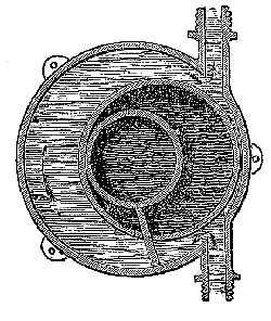
Patented in England by John Trotter of London in 1805. Like many rotary engines, it had another life as a pump, and it is shown here in the form of water pump, complete with three handy mounting lugs. The inner and outer cylinders are fixed, and the middle one rotates. The piston was a rectangular and loose piece of brass or other metal fitted between the two fixed cylinders.
According to Thomas Ewbank, writing in the USA, "...it was reinvented here a few years ago by a mechanic who was greatly distressed on finding that he had been anticipated. A notice of it may therefore prevent others from experiencing a similar disappointment." There is a constant refrain of reinvention in the history of the rotary engine.
From "Hydraulic & Other Machines For Raising Water" Thomas Ewbank, 1850
|
An example of an engine constructed to this design was exhibited at the Agricultural Hall in London as late as 1882. (Norbye)
THE WILLCOX ENGINE: 1806 PATENT
According to Stuart, the engine designed by Robert (or Richard) Willcox was very similiar to that of Flint above, "and differs from Mr Flint's only in the mode of placing of the cocks, and the position of the pipes from the boiler and condenser."
It is not at present known if this engine was ever actually constructed.
No picture currently available
THE CHAPMAN ENGINE: 1810 PATENT

|
| Left: The Chapman Rotary Engine: 1810.
This was devised by William Chapman, and actually built in at least two versions.
It looks like the direct descendant of James Watt's original abutment-bashing machine.
From The History and Progress of the Steam Engine by Elijah Galloway & Luke Hebert, London 1830.
This engine should not be confused with The Chapman Engine of 1973.
|
|
| Left: The Chapman Rotary Engine: 1810.
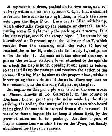
This description was written by Elijah Galloway- who we will meet again- twenty years after this engine was tried and abandoned. There seems to be no attempt to seal the sides of the flaps against the ends of the drum.
This gives an interesting insight into the noise problems you get if you design engines that rely on metal parts whacking into each other at speed.
As in almost all rotary steam engine stories, there is no happy ending.
From The History and Progress of the Steam Engine by Elijah Galloway & Luke Hebert, London 1830.
|

THE TURNER ENGINE: 1816
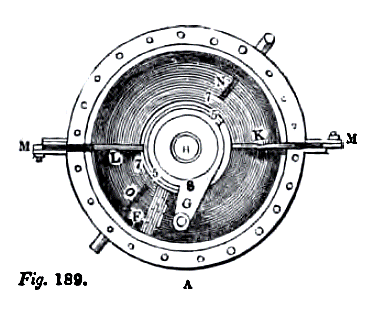
Few rotary engine promoters have had a more appropriate name than Joseph Turner, who came up with this extraordinary design in 1816.
It seems highly unlikely that the doors on which everything depended could be made to open and close without serious steam leakage as they would have to be fully open before the piston arrived, and so partly open for some time before. Another engine using the same unpromising sliding-door approach was the first Galloway engine. Somewhat earlier, the Flint engine used a similiar approach but with revolving doors.
 |
| Left: The Turner rotary engine.
The toroidal casing B contains a circular piston F, mounted on a radial arm G. N,O are the steam ports. The piston was made of several segments with springs to push them outwards against the cylinder "and it is thus made tight without any packing of hemp." (Bourne) Hemp was at the time a common material for packing; it was not very durable and unsuitable for use with superheated steam.
Note doors K, L, with their casings M.
This is a plan view of the engine.
From A Treatise on The Steam Engine in Its Application to Mines, Mills, steam navigation and Railways by the Artizan Society, ed John Bourne, pub 1853 Longmans
|
 |
| Left: The Turner rotary engine.
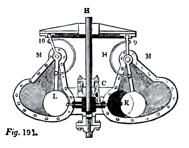
Circular doors K, L in the toroid open and close to let the piston pass, retreating into the casings M when they are making way for the piston. The doors were slightly larger than the internal diameter of the toroid, and fitted into grooves against which they were ground "so they will fit tight without any packing." (Bourne) These statements seem to take a rather optimistic view of the steam-tightness of the arrangements, and are very probably copied from the original patent.
The doors are driven by an eccentric groove Z Y on the underside of a plate attached to the output shaft H above the engine, which moves levers 9, 10; these are connected to the doors by curved rods H, which pass through stuffing boxes in the engine casing. According to Bourne the plate also operates the admission and exhaust valves.
From A Treatise on The Steam Engine in Its Application to Mines, Mills, steam navigation and Railways by the Artizan Society, ed John Bourne, pub 1853 Longmans
|
 |
| Left: The Turner rotary engine.
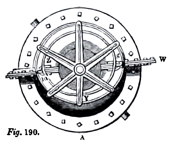
The eccentric groove Z Y carried on a star-shaped plate with reinforcing ribs. Door-operating lever 10 can be seen on the left.
Plan view.
From A Treatise on The Steam Engine in Its Application to Mines, Mills, steam navigation and Railways by the Artizan Society, ed John Bourne, pub 1853 Longmans
|
 |
| Left: The Turner rotary engine.
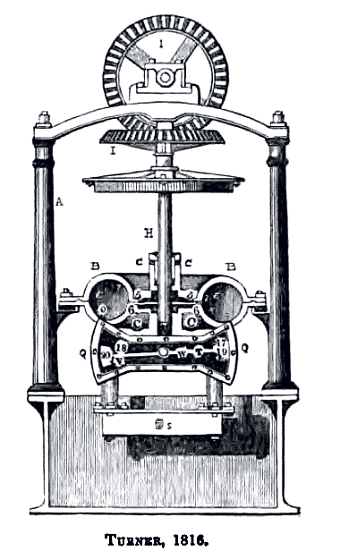
One of the unusual features of the Turner engine was its vertical output shaft; this was probably adopted to avoid unbalanced gravity forces on the swing doors. This necessitated bevel gears I above the engine to drive the usual horizontal shafting.
Further research (in Galloway) has shown that the lower structure Q underneath the engine toroid is indeed a sort of valve chest. T,V are boxes or cups at each end of a lever pivoted about W. How these "valves" were supposed to work and how they were actuated currently remains obscure- possibly there was some sort of cam on the main shaft.
S is the condenser, presumably of the jet type, and looking rather small for its purpose.
Galloway says "There are defects of a sufficiently prominent nature to account for its failure." He went on to theorise that the rather weedy-looking semi-circular rods aat H above would be liable to bend, leaving a closed door in the path of the oncoming piston. He says the resulting collision would leave the engine "injured beyond repair" and one can hardly disagree.
Whether this engine was ever built and tested is currently unknown.
From A Treatise on The Steam Engine in Its Application to Mines, Mills, steam navigation and Railways by the Artizan Society, ed John Bourne, pub 1853 Longmans
|
THE POOLE ENGINE: 1817
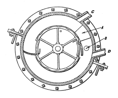
Moses Poole patented this engine in 1817; his patent contains a lot of detail on the problems of sealing the engine. He clearly recognised even at this early date that this was the major problem to be overcome in making an efficient rotary engine.
|
| Left: The Poole Rotary Engine: 1817.
The rotor carries two hinged flaps which are pushed back into recesses by the wheel B fixed to the casing, so they can pass the fixed abutment A; after that the pin at the top of the rotor catches on a lever projecting from each flap and pushes it out again to touch the casing wall. Quite frankly I'm not sure how this last bit was supposed to work.
Steam enters at C and leaves at D. The sinuous shape on the rotor periphery is a channel to contain packing to seal the ends of the rotor.
From "Norbye"
|

THE ROUTLEDGE ENGINE: 1818
In 1797 Joshua Routledge patented an engine which was again similiar to Watt's 'abutment' engine, but with only one flap and one 'piston'. It seems strange that so many people thought it was quite alright to design an engine in which the components hammered into each other as it worked. it is difficult to believe that such engines would have worked for long, even if they had been sound in all other respects.
Joshua Routledge is better known for inventing an improved slide-rule.
 |
| Left: The Routledge rotary engine: 1818
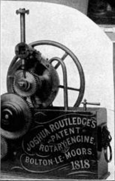
At last a picture of the Routledge engine has been found. In fact, the model of it shown here is preserved in the Science Museum, London, presumably in their stores because I have never seen it on display. The picture gives no clue as to the internal operation. The purpose of the gear wheels is unknown; they did not operate valvegear.
The engine is mounted on a cast iron tank.
Source: Every-Day Science: Volume VI: The Conquest of Nature by Henry Smith Williams, pub Goodhue 1910
|
 |
| Left: The Routledge rotary engine: 1818
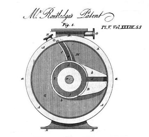
Mr Routledge's patent has been tracked down. As expected there is a hinged flap C, which Routledge calls a 'steam stop' and one piston Bb. The box D allows flap C to swing out of the way when the piston is passing. The steam inlet G is on the side of this box; H is the exhaust port. Since they are of almost the same size, and there is no inlet valve to give cut-off, it seems that Mr Routledge was not interested in expansive working of the steam.
Source: The Repertory of Patent Inventions, and Other Discoveries and Improvements Volume 33, Second Series, August 1818
|
 |
| Left: The Routledge rotary engine: 1818
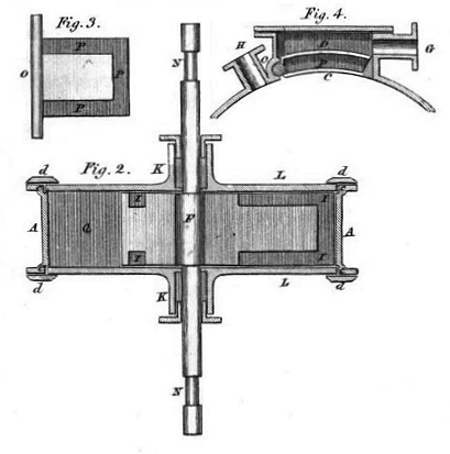
In Fig 4 the flap C can be seen retracted into the box D. The dark section II was intended to hold a packing material such as hemp.
Source: as above
|
THE STILES ENGINE: 1819
 |
| Left: The Stiles Rotary Engine: 1821.
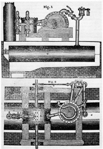
One early American rotary engine was built in Baltimore in 1819 by George Stiles, a former mayor of that city, and his son John S. Stiles. Three years before, commentator Hezekiah Niles, ever ready to praise and encourage American ingenuity, announced with pride that a Mr Curtis of Massachusetts had achieved "a desideratum in steam engine, a complete rotary motion without a flywheel or balance, an object of long and arduous research in Europe, of the greatest advantage to the mechanical world." The engine was reportedly "composed only of a cylinder containing a shaft-wheel with valves" and was touted as "vastly superior to those of Watt and Bolton, Evans, or any subsequent constructor" Curtis had one of his engines operating the sawmill of A. and N. Brown of Manhattan Island and had "after encountering a long series of difficulties . . . established a manufactory in Baltimore."
The Stiles engine was was supposed to have been used by the Stiles for boring cannon during the War of 1812, then was used for ordinary shop work, and was finally used to operate a gristmill. After five years it was said to be "still working with equal power, without having received any material repairs." The four virtues claimed for it were its lightness, compactness, cheapness, and simplicity of motion.
The last point was clinched, in the mind of Hezekiah Niles, by the fact that the one then "working at Mr. Stiles' factory and mill is under the care of a black man, whose chief qualities, as needful to its management, are sobriety, and attention." I'm not quite sure what to make of that. Stiles, besides carrying on other types of work, made these rotary engines for general sale. In 1817 they even placed one of their engines aboard the boat Surprise, a steamboat which was said to be quite fast.
The internal construction of the engine is currently obscure.
Quotes from Niles' Weekly Register, volume 17 (16 October 1819), pages 97-98
|

|
| Left: The Stiles Rotary Engine: 1821.
This is testimony in the Reports of Committees, Washington, 7 Dec 1831, in a 'General Report on the Explosions of Steam-boilers', by Ebenezer A Lester (of Boston, Mass) who is known to have patented a steam boiler on 14 May 1827. Other sources say he patented a 'Pendulum Steam Engine' on the same date. It appears Lester met Stiles in 1814, who was then a manufacturer at Baltimore, Maryland.
|
THE CARTER ENGINE: 1821

|
| Left: The Carter Engine: 1821.
This was described by Bourne as an improvement on the first Hornblower engine. The drawing actually shows the drum H containing the one-way clutches, rather than the steam cylinder, which was presumably unchanged.
According to Bourne, it worked thus: the ends of the rotor NN are not concentric with the casing, but jam against the shoes when it rotates in the direction of the arrows. The springs p carry the shoes round with the rotor.
This seems like a very minor improvement, if improvement it was, and certainly not enough to make the Hornblower engine anything like a practical proposition.
Whether Mr Carter actually built an engine is currently unclear.
From A Treatise on The Steam Engine in Its Application to Mines,Mills, steam navigation and Railways by the Artizan Society, ed John Bourne, pub 1853 Longmans
|
THE WRIGHT ENGINE: 1825
The rotary engine patented by Lemuel Wellman Wright in 1825 appears to have been based on the Poole engine. The rotor carried sealing flaps; instead of a wheel to press the flaps down, the fixed abutment was in the shape of a ramp to perform this action. They were forced out again by tail pieces (mounted externally on the flap shafts) striking a wheel. Quite frankly I'm not sure how this last bit was supposed to work, if "external" means outside the casing; perhaps it means outside the rotor but inside the casing.
As with Poole, the patent is mostly concerned with solving the sealing problems; this was clearly recognised as the major obstacle to economical operation. The ends of the flaps had secondary flaps pressed against the outer casing by a steel strip spring.The fixed abutment was to be sealed by a piece of brass pressed against the rotor by a spring. The ends of the rotor were sealed by rings pressed against the stationary inside face of the casing by helical springs.
This design, as usual, appears to have had no success. Clearly the Wright engine was the wrong engine.
No picture currently available
THE EVE ENGINE: 1825
|
| Left: The Eve Rotary Engine: 1825.
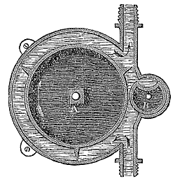
In 1825 Mr Joseph Eve, a US citizen, patented a rotary engine in London. It is shown here in the form of water pump, complete with handy mounting lugs. The two rotating parts are geared together outside the casing.
It is not currently known if this engine was ever built and tested.
From "Hydraulic & Other Machines For Raising Water" Thomas Ewbank, 1850
|
 |
| Left: The Eve engine animated.
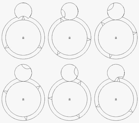
This animation follows all the contemporary drawings in showing the cutout in the little "revolving-door" as a portion of a circle. You will note that this gives a poor fit with the protruding vane of the rotor as it moves through the cut-out.
If this is correct then for part of the cycle there is a serious leakage path directly from inlet to exhaust, with dire implications for the efficiency of the engine. This is not the only engine in this gallery which shows this fault.
This animation is kindly provided by Bill Todd
|
 |
| Left: The Eve rotary engine.
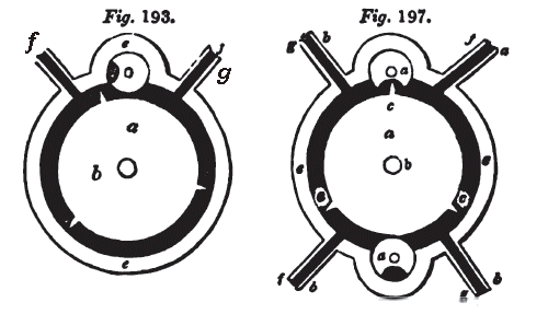
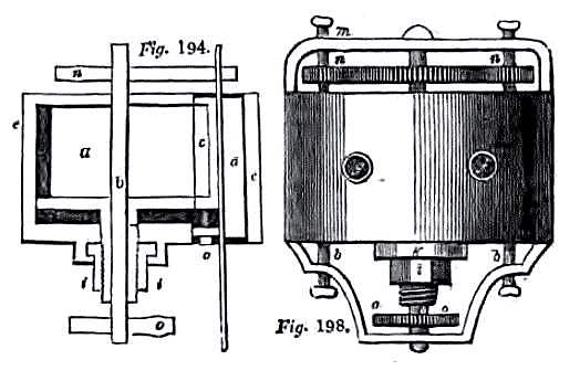
Another rendition of the Eve engine, rather more crudely drawn, and probably taken from the original patent drawings. In Fig 193, f is the steam inlet and g the exhaust, so the rotor goes round in an anti-clockwise direction. The blades on the rotor are intended to touch the casing walls, giving a seal; this is quite impractical, as we have seen before. The revolving-door roller at the top (which is described as conical, presumably part of the sealing scheme) rotates by gearing so that its cut-out is in just the right place at the right time to allow the rotor blades to pass, touching the surface of the cut-out to maintain a highly implausible line seal. At other times it is supposed to maintain a seal by line contact with the main body of the rotor.
From A Treatise on The Steam Engine in Its Application to Mines,Mills, steam navigation and Railways by the Artizan Society, ed John Bourne, pub 1853 Longmans
|
It can be seen in Fig 193 that once the rotor blade has passed the inlet port, the pocket of steam in front of it cannot expand but it carried uselessly around until it encounters the exhaust port. Only about a third of the volume of the engine is actually doing any work. The double version on the right seems to makes better use of the casing volume, but is still hopelessly impractical. There is no expansive use of steam so even if every other aspect of the engine worked, it would uneconomical.
 |
| Left: The Eve rotary engine.
One end of the casing was a movable plate that could be moved inwards by an external screw i to take up wear at the ends of the rotor. This can be seen under the rotor a at the left. The shaft carrying the roller is angled to allow for its conical shape.
The right drawing shows the gearing n,n that drives the revolving-door or doors from the main shaft. Note the thumbscrews.
From A Treatise on The Steam Engine in Its Application to Mines,Mills, steam navigation and Railways by the Artizan Society, ed John Bourne, pub 1853 Longmans
|
 |
| Left: The Eve rotary engine.
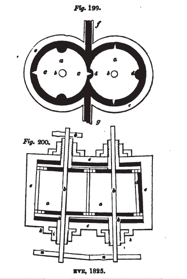
This is a third version of the engine, which there are two rotors geared together, each with appropriate cut-outs to allow the blades of the other to pass. This time the two rotors are conical, presumably to aid sealing.
From A Treatise on The Steam Engine in Its Application to Mines,Mills, steam navigation and Railways by the Artizan Society, ed John Bourne, pub 1853 Longmans
|
 |
| Left: The Eve rotary engine
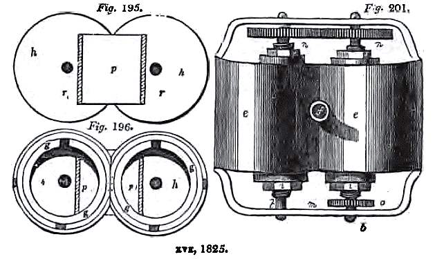
At right, an external view of the two-rotor engine.
From A Treatise on The Steam Engine in Its Application to Mines,Mills, steam navigation and Railways by the Artizan Society, ed John Bourne, pub 1853 Longmans
|
THE MARRIOTT ENGINE: 1828
Henry Marriot (ironmonger) and August Siebe (machinist) patented a rotary pump where sealing blades moved in slots in a drum-style rotor. A stationary cam combined with a spring arrangement forced the blades outwards against the inside of the cylinder, hopefully providing sealing.
To be quite honest, I am not at the moment certain that this was one of the many designs intended both as pump and steam engine, but for the time being it gets the benefit of the doubt.
THE STEEN ENGINE: 1831
The Steen engine is known only through the memoirs of the great engineer James Nasmyth, inventor of the steam hammer. The stage payments made by Robert Steen allowed Nasmyth to build up his workshop; the exact dates of the project are not known but it must have been shortly after 1831. We note that Nasmyth tried to warn him, but...
"The chief of these extraneous and, I may say, disturbing jobs, was that of constructing a rotary steam-engine. Mr. Robert Steen had contrived and patented an engine of this sort. He was a dangerously enthusiastic man, and entertained the most visionary ideas as to steam power. He was of opinion that his own contrivance was more compact and simple, and possessed of more capability of producing power from the consumption of a given quantity of fuel, than the best steam-engines then in use. I warned him of his error; but nothing but an actual proof would satisfy him. He urgently requested me to execute his order.He made me a liberal and tempting offer of weekly payments for my work during the progress of his engine. He only required that I should give his invention the benefit of my careful workmanship. He considered that this would be sufficient to substantiate all his enthusiastic expectations. I was thus seduced to accept his order."
"I made the requisite drawings, and proceeded with the work. At the same time my own machine tools were in progress, though at a retarded pace. The weekly payments we're regularly made, and I was kept in a sort of financial ease. After three months the rotary engine was finished to the inventor's complete satisfaction. But when the power it gave out was compared with that of a good ordinary steam-engine, the verdict as to consumption of fuel was against the new rotary engine. Nevertheless, the enthusiastic projector, "tho' vanquished he would argue still," insisted that the merits of his contrivance would sooner or later cause it to be a most formidable rival to the crank steam-engines. As he was pleased with its performances, I had no reason to be dissatisfied. I had done my part in the matter, and Mr. Steen had done his. His punctual weekly payments had assisted me in the completion of my tools; and after a few months more labour I had everything ready for starting business on my own account."
|
Source: The Autobiography of James Nasmyth Engineer edited by Samuel Smiles & AF Collins, pub Cambridge University Press 1931
No other trace of Robert Steen's engine has so far been found.
THE WOODHOUSE ENGINE: 1834
 |
| Left: The first Woodhouse rotary engine: 1834
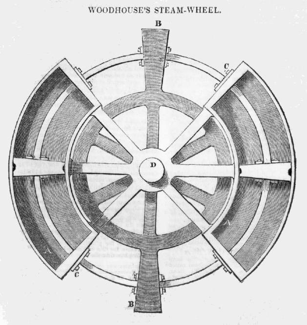
This design was put forward by James Woodhouse, although it was purely theoretical, and very far from complete, as he admitted himself.
He said: "The grand points of difficulty are the mutation of action, the valve and the mode of backing when required. Should any of your readers be inclined to follow up the invention, possibly it may in the end produce a more ready application of steam-power than has hitherto been adopted."
From Mechanics Magazine 13 Dec 1834
|
"The grand points of difficulty are the mutation of action..." The wheel can only oscillate, as the pistons move back and forth in their curved cylinders, so presumably this refer to the conversion of oscillation into rotary motion, perhaps by ratchets or a crank arrangement. The latter in particular rather undermines the notion of a rotary engine.
And the other difficulties: "...the valve and the mode of backing when required." The reference to a valve in the singular leads to the worrying possibility that Mr Woodhouse was not aware that both inlet and outlet valves are required in a steam engine. "...the mode of backing..." presumably refers to reversing the engine, which would be done by manipulating the valvegear.
You could argue that this engine should be classified as either a steam-wheel (but surely not as it as it does not rotate continuously) or, more plausibly, as a vibratory engine.
Given the purely theoretical nature of this half-baked engine, you might wonder why it was published. (and on the front page, too) It must have been a slow week for mechanical news.
THE GALLOWAY ENGINE: 1834
 |
| Left: The Galloway Rotary Engine: 1834
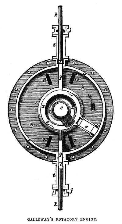
This engine is ascribed to someone called Galloway by Luke Hebert, author of "The Engineer's And Mechanic's Encyclopedia". My copy was printed in 1846 but has a preface dated 1835. Elijah Galloway patented two completely different designs in 1840 and 1846; see Page 2 for the next one.
I quote:
"...c is a rectangular piston firmly connected to the smaller cylinder x, and furnished round its sides with metallic packing; g,g are two sliders moving in steam tight cases i, and in rebates formed in the cylinder covers; they form the steam abutments, and are drawn alternately within the slide cases, to allow the piston to pass by means of a cam on the shaft, which operates on crossheads attached to the slide rods, which latter work in stuffing boxes."
Steam entered and left via the rectangular ports in the side of the cylinder, labelled 6, 7, 13 and 14. The sliders would need to move pretty nippily to get out of the way of the rotating piston C, so there would be some quite large accelerations of reciprocating components. This runs rather counter to the basic philosophy of the rotary engine. The sliding-door principle was used in the Turner engine above.
The name Galloway is suggestive. The Galloway boiler was a well-known type; however, it appears to be due to not to Elijah Galloway, but W & J Galloway and Sons, a well-known firm of engineers, boilermakers and iron founders based at Knott Mill Iron Works, Manchester. (Elijah Galloway, in contrast, appears to have been based in Middlesex) The boilermakers may have been relatives, of course.
Hebert merely gives a description, and no information as to whether this engine was actually built.
|
THE YULE ENGINE: 1836
 |
| Left: The Yule rotary engine
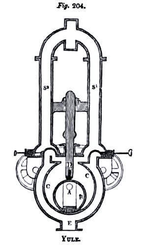
This engine was invented by a Mr John Yule of Sauchiehall St, Glasgow. He was described as a 'practical engineer' in Mechanics Magazine, and received a Scotch patent for the idea on 18th November 1836. According to Bourne's book, in 1853 it had been "working smoothly for some years." so if that really was the case it seems to have been blessed with greater longevity than most rotary engine designs, as I have now determined that it was was introduced in 1836. It has therefore been moved to page 1 of the Rotary Steam Engine Gallery.
The Yule engine had an eccentric rotor B, with a sliding abutment D bearing on it; this abutment was moved up and down not only by the rotor, but also two return cranks mounted on the rotor shaft gearwheels. Steam entered via pipes S1 or S2, depending on the direction of rotation selected by the valves at left and right, and exhausted through pipe E. The flywheel and its shaft are not shown here.
There must have been valves at the bottom of pipes S1 or S2 to control steam admission during rotation; they were probably rotary valves actuated by the small gearwheels on either side, which were in turn driven from the rotor shaft.
From A Treatise on The Steam Engine in Its Application to Mines, Mills, steam navigation and Railways by the Artizan Society, ed John Bourne, pub 1853 Longmans
|
 |
| Left: The Yule rotary engine, as analysed by Franz Reuleaux
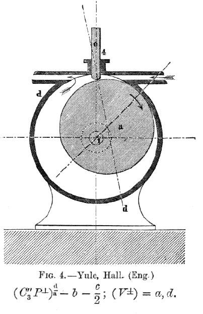
Reuleaux pointed out the difficulty of sealing the line contact between the sliding abutment and the rotor. The formula at the bottom is a kinematic description of the engine using his own notation.
This diagram seems to have got the position of the steam exhaust wrong. In all the other drawings it is at the bottom of the cylinder.
From The Kinematics of Machinery by Franz Reuleaux, pub 1876
|
 |
| Left: The Yule rotary engine: longitudinal section
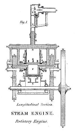
The eccentric rotor is at F, and the sliding abutment at R. This image shows the flywheel W, driven from the rotor shaft by two sets of spur gears G,G. As for many rotary engines, the flywheel seems disproportionally large compared with the engine, probably in an attempt to smooth out severe cyclic torque variations.
Image from unknown book plate, circa 1840
|
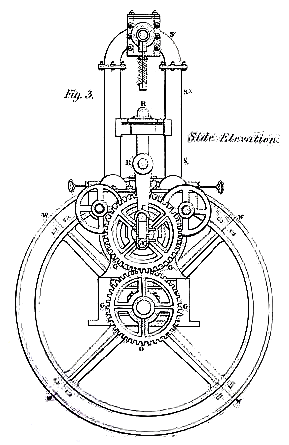 |
| Left: The Yule rotary engine: side elevation
It appears that the throttle valve was at the top of the two vertical pipes, for no obvious reason, making for a tall and cumbersome engine. It is also puzzling that the flywheel was not mounted directly on the rotor shaft, which would have made the engine somewhat more compact; and gearwheels cost money.
John Yule died in 1877. There is an obituary for him at Graces Guide. Here is the part relevant to us:
"Another invention, which was quite a success, was his rotary engine, an example of which was erected at the Phoenix Iron Works, where it did good service as a prime mover. The construction of a good rotary engine was a problem which many engineers had attacked, but in which few had met with any success that was really worthy of the name."
|
Hmmm. And yet the Yule engine did not prosper. The next part of the obituary gives a hint as to why:
"Mr Yule also tacked the "Will of tho Wisp", problem, known as perpetual motion, as he believed that no engineer was worthy of the name who had not made some attempt to fathom the depth of Nature's laws in reference to force and motion. Of course, he discovered for himself the fact that perpetual motion was a chimera, but he incidentally gained a deep insight into the first principles of mechanical science."
|
This does not give a good impression of Mr Yule's capabilities as an engineer.
Image from unknown book plate, circa 1840
|
THE WOODHOUSE ENGINE: 1839
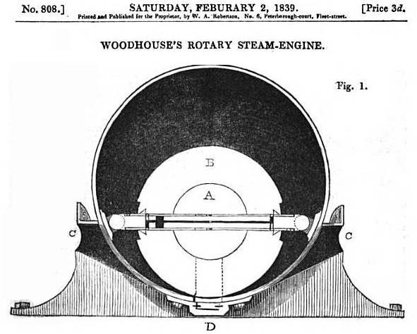 |
| Left: The Woodhouse rotary engine: 1839
This design was put forward by James Woodhouse of Barnstaple, who we met before in 1834. The accompanying text describes it as "sketches of a rotary engine" with no hint that it had been built or patented. "[It] is intended as an improvement on Trotter's, patented many years since (1805)by avoiding the difficulties which that invention presented in the working parts upon its revival by Earl Dundonald.(Cochrane)"
In fact his plan has little in common with either Trotter or Cochrane's engines. The horizontal item consists of two slides telescoping together, and sliding in and out of the central rotor. Mr Woodhouse is extremely vague about the valvegear, talking about "small moveable plugs, or spring valves" and it seems safe to assume he was strictly an armchair inventor.
From Mechanics Magazine, 2 Feb 1839
|
Once again a purely theoretical engine was published on the front page of Mechanics Magazine. Clearly another slow week for news.

THE BALDWIN & BAKER ENGINE: 1839
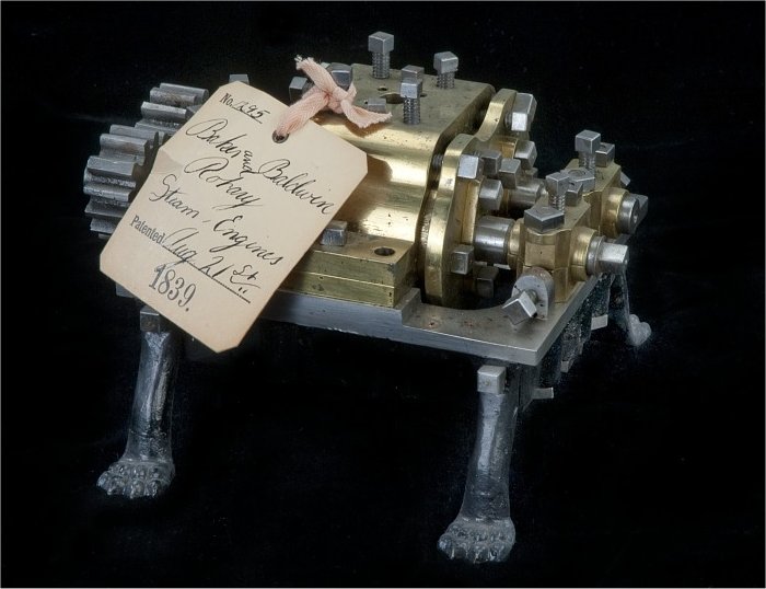 |
| Left: The Baldwin & Baker rotary engine patent model: 1839
This is another model submitted to the US patent office, by Samuel Baldwin and William Baker of New York state. The US patent system from 1790 to 1880 required a working model to be submitted if you wanted a patent; this has been presented as a help to unsophisticated inventors who would have trouble getting engineering drawings made, but since proper drawings were essential to put into the patent document it's hard to see how it can have helped. I have a dark suspicion that perhaps the insistence on a working model was to slow down a flood of perpetual motion machines. The engine was awarded US patent No 1,295.
This description comes from the 1939 Catalog of the Mechanical Collections of the Division of Engineering United States Museum Bulletin 173 by Frank A. Taylor:
"(An engine) in which two cams turn together in a closed casing so that steam admitted to the casing will force apart abutments on the cams and cause the cams and the shafts on which they are mounted to turn."
Note the spur gears at left which synchronised the two 'cams'. Note also the rather cute clawed feet.
|
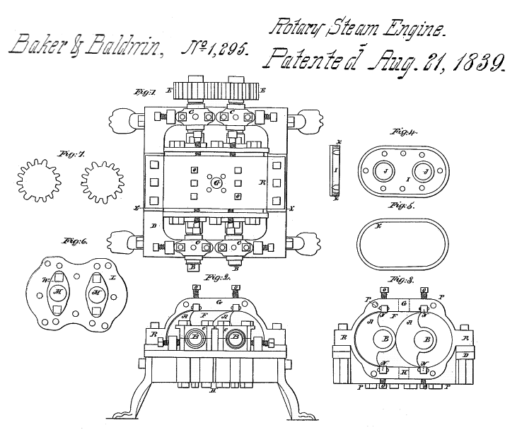 |
| Left: The Baldwin & Baker rotary engine patent: 1839
The first thing I noticed on this patent was that the animal feet corresponded exactly with the model.
However, getting serious, what might be called the non-linear gears (see gearwheels from hell) in Figure 7, are used to make the two rotors synchronise properly so they maintain a tight seal with each other- at least so it says in the patent text. Since the rotors depend on a line contact between for sealing, even if the non-linear gearing works as claimed, there won't actually be much sealing. The engine is designed to be reversible by swopping over steam ports.
Note the large number of set-screws for adjusting rotor separation and packing tightness. This is not a good sign.
|


