Updated: 10 June 2026
Another Hardy Engine Engine updated here


Rotary Steam Engines: Page 4 |
Updated: 10 June 2026 |
![]()
THE HENDEY ROTARY ENGINE: 1870
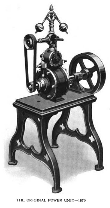
| Left: The Hendey rotary engine: 1870
|
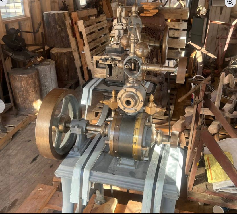
| Left: The Hendey rotary engine: 1870
|
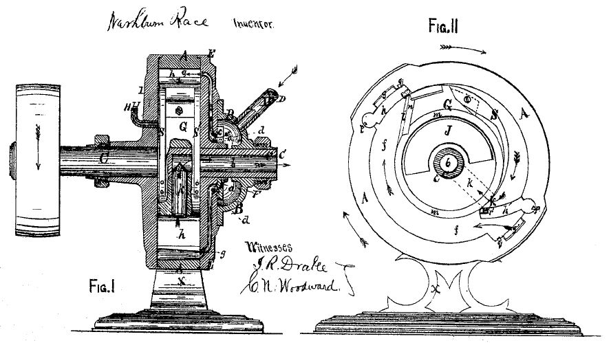
| Left: The Race rotary engine: 1871
|
The engine uses two swinging abutments h and h' that double as inlet valves, but this time they are constrained in the hope of making them move smoothly, rather than just banging about in the cylinder. The valves open because of the steam pressure behind them; the speed of opening is controlled by the incline i attached to the rotor. (Top left of Fig 2) The inlet valves are closed again by the ramp S, also attached to the rotor. Steam exhaust is through the duct k into the hollow central shaft.
Apart from his patent, Washburn Race is unknown to Google, so it is fair to conclude that this engine did not thrive.
THE STOCKER ROTARY ENGINE: 1872
![]()
| Left: The Stocker Rotary Engine: 1872
|
THE FAUCETT ROTARY ENGINE: 1872
![]()
| Left: The Faucett Rotary Engine: 1872
|
THE SHAW & BAKER ROTARY ENGINE: 1873
![]()
| Left: The Shaw & Baker engine: 1873
|
| Left: The Shaw & Baker engine: 1873
|
The Baker company still exists, making water-supply products. Here are a few more details from on the rotary engine from The Baker Monitor.
"It all began in 1872 with the designing of a rotary steam engine by Allen S. Baker and Levi Shaw. Mr. Baker took the design to a Milwaukee firm to be built and the tests looked promising. In April of 1873, Caleb Snashall and L. M. Mygatt from the hardware store and Almeron Eager and W. S. Smith from the general store, proposed to Baker and Shaw that the six of them each subscribe $1,000 to organize a company to build rotary steam engines and also run a machine shop repair business. Some stories say that Mr. Eager and Mr. Baker formulated the idea while going for a buggy ride and having a picnic together at Liberty Pole Hill. In any case, the organization was formed and the following officers elected: President, Caleb Snashall; Treasurer, Almeron Eager; Secretary, W. S.Smith. Allen Baker was made Foreman and General Superintendent. The company was named the A. S. Baker Company. These six were very enterprising men but very different from each other in their talents and aspirations. Some were primarily interested in making money and some just loved to build things; but all had a great love for Evansville and wanted to see the city grow and thrive.""Machinery was ordered and a two story frame building was erected at what is now the corner of Enterprise and Church Streets. The "Shop" was opened for business in July of 1873. They made two or three rotary steam engines but soon discontinued them because they proved uneconomical to operate. The only other activity carried on during that summer was the repair of reapers and mowers." |
ANOTHER HARDY ROTARY ENGINE: 1873
![]()
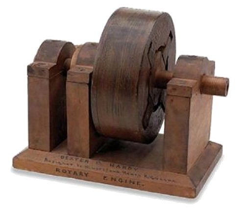
| Left: Patent model of the Hardy Rotary Engine of 1873
|
| Left: The Hardy Rotary Engine of 1873
|
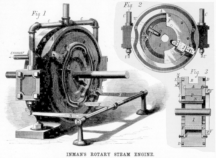
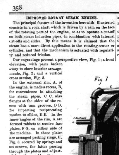
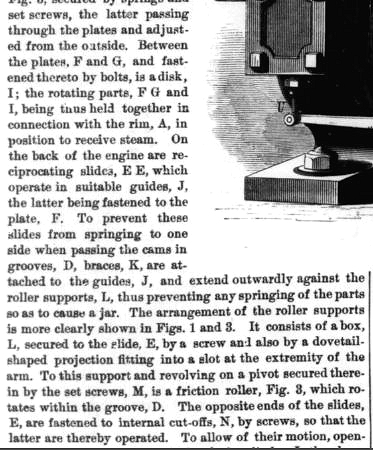
| Left: The Inman Rotary Engine: 1873
|
| 
| 
| Left: The Inman Rotary Engine: 1873
|
| 
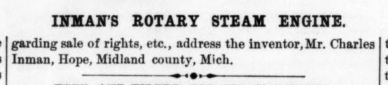
| Left: The Inman Rotary Engine: 1873
|
| Left: The Moss Rotary Engine: 1875
|
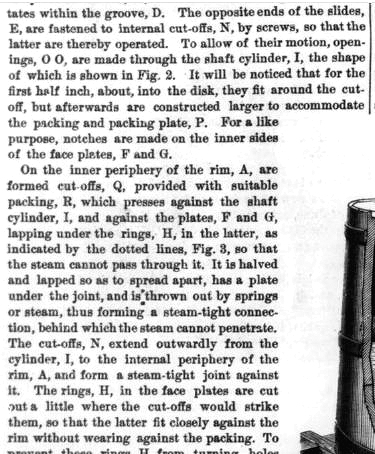
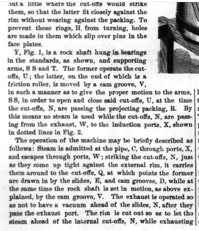
The four rotary steam engines below were illustrated in the US journal "Manufacturer & Builder" for June 1880. Extracts from the contemporary description are in green text. The seals and packings- usually the Achilles Seal of these machines- is highlighted in red or pink, where feasible.
"The Pillner-Hill has two cylindrical overlapping chambers, and two systems of rotary pistons, which may be compared to cogwheels. These wheels, by the close contact of their cogs, prevent the passage of steam between them, and they are adapted steam-tight to the interior of their cylinders by metallic packing in the tips of their teeth."
The Pappenheim pump appears again. This design appears to be reversible; by rotating the plug cock on the right steam can enter on either side of the rotors. There seems no possibility of expansive use of steam; it probably worked but it would have been dreadfully inefficient. The design is related to the gear-type oil pumps widely used in car engines. This was the type of engine built by Murdoch.
Once more the exhaust "eduction" pipe is no bigger than the inlet. The expansive use of steam looks to be impossible. Engines like this are inherently reversible, given suitable steam connections.
"...has four distinct pistons, which slip in and out in the eccentric hub."
At first this looks unworkable as the steam volume expands and then contracts again before the exhaust port is reached allowing no work to be done. However the pipe at the left may not be the exhaust, but an alternative steam inlet for reversing, and there is probably an exhaust port at the bottom, not shown in this contemporary drawing.
"The engine has three pistons, two abutments, and two induction and eduction ports."
Here there is at least the possibility of expansive use of steam. However, note that the exhaust "eduction" pipe is no bigger than the inlet. This looks suspicious, but might just be bad drawing.
See also the Knowles rotary engine, which has its own page. Its exact date is unknown but appears to be around 1880.
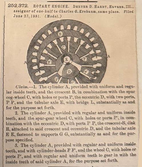
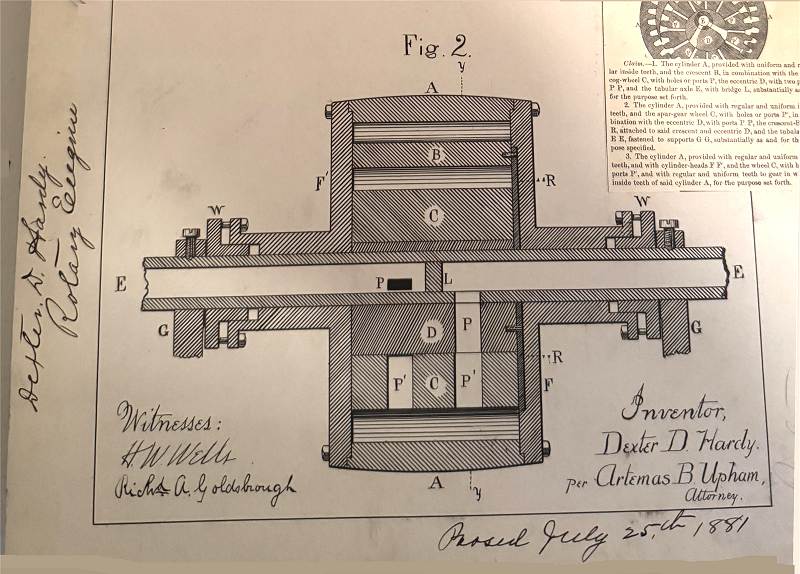
Dexter Hardy did not give up easily. In 1882 he was granted US patenr 252,372 for an unusual kind of rotary engine with interlocking gear wheels. The text of the patent has not yet been examined by the Museum Staff, but it appears that the inners gearwheel was turned by steam pressure on the sides of the gear teeth, with steam going in and out via the ports P. The port E is presumably either the steam inlet or its exhaust.
The lunette B separates the two sides of the engine.
Note how the teeth of the gears are snuggled close together at the bottom of the drawing, which looks as if it would give good sealing. But... modern gears have an involute tooth form that gives a rolling action rather than sliding, to reduce friction. The gear teeth only make a line contact with each other so sealing will in fact be virtually impossible.
If the engine was built according to the drawing I don't think it could rotate.
There is an earlier Hardy engine of 1859 here.
There is an earlier Hardy engine of 1868 here.
There is an earlier Hardy engine of 1873 here. (This page)
All four Hardy engines are of completely different design, indicating that he was prepared to try anything.
There is some more information on the Hardy engine here.
Here is a vertical section of the Hardy engine.
SELECTED ROTARY ENGINES OF THE 1880s
.
Left: The Pillner-Hill rotary steam engine; cross-section. An English design of the "gear-pump" type.
Left: An anonymous design, (though it looks very much like the Birdsall Holly engine) again of the "gear-pump" type.
The design is similiar to the Roots blower widely used as a supercharger for IC engines.
Left: Another anonymous design reminiscent of the Shorrocks blower, which was once much used for supercharging IC engines.
The twiddly bit on the right appears to be just a steam admission valve.
Left: A anonymous rotary design that typifies a common approach to the problem; hinged "abutments" that swivel out of the way as the three "pistons" on the rotor go past.
Rotary steam engine designers were very fond of "abutments" that miraculously swung out of the way (or were knocked out of the way) with great precision at convenient times, though they inevitably made the engine inherently non-reversible, like this effort here. Given that it has three pistons and two abutments, this might be the Cartwright engine of 1797.
![]()
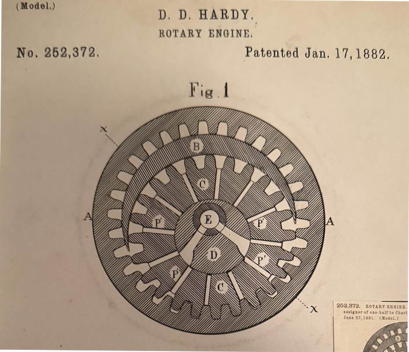
Left: The Dexter Hardy Engine: 1882
Left: The Dexter Hardy Engine: 1882
Left: The Dexter Hardy Engine: 1882
![]()

|