Updated: 21 Aug 2011
Sir George Airy and Cochrane's engines
With a guest appearance of Stephenson's Rocket.


Cochrane's Rotary Steam Engines. |
Updated: 21 Aug 2011 |
|
The name of Lord Dundonald is frequently mentioned in the General Meeting of the Institute of Engineers, and it sounded familiar, so I thought some investigation was called for. And remarkable the results were.
Rear Admiral Lord Thomas Cochrane, Tenth Earl of Dundonald (1775-1860), had an extraordinary career. He was the son of Archibald Cochrane, the ninth Earl of Dundonald. (1749-1831) The ninth Earl was an unsuccessful inventor who attempted amongst other things, new processes for alkali manufacture; the family was greatly impoverished due to losses over these schemes.
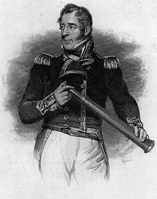 | Left: Thomas Cochrane during his naval career.
|
At various periods of his life Cochrane, following in his father's inventive footsteps, took out patents for lamps to burn oil of tar, for the propulsion of ships at sea, for facilitating excavation, mining and sinking, and for other purposes; as early as 1843 he was an advocate of the use of steam and screw propellers in warships.
The Cochran Boiler is a type that is still being made and used. However, you will note that the name is spelt differently, and as far as I can tell at the moment, it was not one of Thomas Cochrane's inventions.
Cochrane became a strong advocate of rotary steam engines. He produced at least four rotary engine designs, none of which had any success. I am still in the process of sorting out the order in which they were built, patented, tested and abandoned, so for the moment I have just called them Type 1, etc.
You can read more about Cochrane's remarkable career here.
In 1834 Cochrane had a pair of rotary engines built for locomotive work, probably by John Seaward & Co, of the Canal Ironworks, Limehouse, on the river Thames, who had built some of his earlier marine rotary engines. He contacted the London & Midland Railway, to arrange for tests, and the locomotive selected for modification was none other than Stephenson's Rocket.
It was available, and had straight axles unlike the cranked axles of the "Planet" class of locomotive, which made the modifications easier.
 | Left: Lord Dundonald's rotary engine; Type 1.
|
 | Left: Lord Dundonald's rotary engine; Type 1.
|
Cochrane (now Lord Dundonald) told the LMR that he was so confident that the expense of the modifications would not exceed �30 that he would pay any additional cost himself. In the event the cost was nearer �80. A trial was made on or about the 22nd of October 1834, and it was this debacle that inspired George Stephenson's comment at the General Meeting of the Institute of Engineers, that "the engine could not be made to draw a train of empty carriages".
 | Left: Lord Dundonald's rotary engine applied to a locomotive. From a pamphlet he produced in 1833, before the Rocket modifications.
|
Here are some other Cochrane engines that have appeared in the literature. The dates of construction or testing are not known; the diagrams appeared in print decades afterwards.
 | Left: The Cochrane Rotary Engine; Type 2
|
 | Left: The Cochrane Rotary Engine; Type 3
|
 | Left: The Cochrane Rotary Engine; Type 3
|
 | Left: The Cochrane Rotary Engine; Type 4. 1844
|
 | Left: The Cochrane Rotary Engine; Type 4. 1844
|
This is the form of engine that was tested in the steam-frigate Janus.
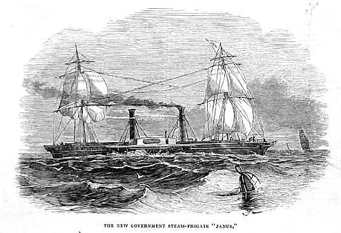 | Left: The steam-frigate Janus: 1844
|
Note that the Janus had two square-rigged masts; she would not be helpless if the engines failed. This was not a special precaution to cope with undependable rotary engines; it was the common practice at a time when inefficient engines gave only a limited range under steam, and coaling stations were far apart.
"This contrivance has not yet realised any great success, and the prevailing opinion among engineers appears to be that it will not supercede ordinary engines. Similar engines have been tried on many former occasions, but they have always been found to involve either a ruinous amount of leakage, or such a degree of friction as to make the plan impossible in practice." said John Bourne in 1853.
![]()
EXTRACT FROM AUTOBIOGRAPHY OF SIR GEORGE BIDDELL AIRY: 6th & 7th of January, 1846
This extract from the autobiography of Sir George Airy gives a few tantalising glimpses of encounters with rotary engines in the naval dockyard at Portsmouth and on board the "Janus". It is an extremely rare eye-witness account:
"As soon as possible we repaired to the Dock Yard and presented ourselves to the the Admiral Superintendant- Admiral Hyde Parker (not Sir Hyde Parker). Found that the "Janus" had not arrived: the Admiral Superintendant (who does not spare a hard word) expressing himself curiously thereon. But he had got the proper orders from the Amiralty relating to me: so he immediately sent for Mr Taplin, the superintendant of machinery: and we went off to see the small engine of Lord D--d's construction which is working some pumps and other machinery in the yard. It was kept at work a little longer than usual for us to see it. And I have no hesitation in saying that it was working extremely well. It had not been opened in any way for half a year, and not for repair or packing for a much longer time...
This morning we went to the Dock Yard, and on entering the engine house there was Shirreff, and Lord D--d soon appeared. The "Janus" had come to anchor at Spithead last night, and had entered the harbour this morning. ... We had the engine pretty well pulled to pieces, and sat contemplating her a long time. ... We then went on board the "Janus" with Shirreff but not with Lord D--d. The engines were still hot, and so they were turned backwards a little way for my edification. ... The vacuum not good. Then ... it was agreed to run out a little way. But the engines absolutely stuck fast, and would not stir a bit. This I considered a perfect godsend. So the paddle-wheels (at my desire) were lashed fast, and we are to see her opened tomorrow morning."
"This morning (Jan 7th) we all went off to the "Janus", where we expected to find the end of the cylinder (where we believe yesterday's block to have taken place) withdrawn. But it was not near it. After a great many bolts were drawn, it was discovered that one bolt could not be drawn, and in order to get room for working at it, it was necessary to take off the end of the other cylinder. And such a job! Three pulley hooks were broken in my sight, and I believe some out of my sight. However this auxiliary end was at last got off: and the people began to act on the refractory bolt. But by this time it was getting dark and the men were leaving the dockyard, so I left, arranging that what they could do in preparation for me might be done in good time for tomorrow morning."
The autobiography then jumps to 13th November 1847, and no more is heard of the "Janus" and her engines. Why Airy felt it desirable to ineffectually obscure Lord Dundonald's name by rendering it as Lord D--d is currently a mystery.
This passage raises several points. Why were the paddle-wheels lashed fast? Presumably so it would be safe to dismantle the engines, (note the plural- there was probably one engine for each paddle-wheel) which would otherwise have been liable to turn suddenly if wind or tide made the vessel move.
Secondly, Airy talks of reversing the engines. Presumably this was done by using valves to swap over the inlet and exhaust ports.
Finally, it appears that when Airy first saw the "Janus" the engines were working, but shortly afterwards seized solid, probably because they had cooled down. If the packing was adjusted so that a rotary engine worked with reasonable economy when hot, it would be very likely to seize as it cooled and the working clearances closed up.
![]()

|