Today power is derived from water by using turbines, usually to drive electrical generators. However, there is, or rather was, another way- the water engine or water motor. This refers to a positive-displacement engine, often closely resembling a steam engine, with similar pistons and valves. They could be driven from a large natural head of water, the normal water mains, or a high-pressure water supply such as that provided by The London Hydraulic Power Company. (external link) Similar hydraulic networks were built in Hull, Liverpool, Birmingham, Manchester, and Glasgow.
Water supply mains in the UK today work at 10 - 14 psi, though in the 19th century it appears they often ran at higher pressures such as 30 - 40 psi. The London Hydraulic Power supply was at 800 psi.
The term "water motor" was more often used to describe small Pelton-type water turbines driven from a tap, used for light loads such as stirrers in chemical laboratories or sewing machines. A water engine was always a positive-displacement machine.
A separate Water Motor gallery is now open for visitors.
Water engines were at one time used extensively in London, running from the London Hydraulic Power Company network. Even when electric motors began to appear, water engines remained superior for a long time. They were virtually silent, reliable, (no brushes to wear out), very safe (no electric shocks or escaping steam) and could operate in damp or waterlogged conditions quite unsuitable for electricity. They were easy to control, compact, and cheap to run. Knight's American Mechanical Dictionary (1881) gives the following list of advantages: "...the water engine is recommended by the combined advantages of simplicity, neatness, compactness, constant readiness for work, perfect safety, economy while working, and the absolute cessation of expenditure during interruptions and after the work of the day is over."
They were used to drive railway capstans (for moving wagons by rope), railway turntables, cranes, waggon hoists, and so on. Hydraulic engines drove the revolving stages at the London Palladium and Coliseum theatres. A major application was blowing pipe organs. (See below) They were also used to drive water pumps in mines, where their ability to work completely submerged in emergencies was a great advantage.

WATER ENGINE VALVEGEAR
As you stroll through the water engine gallery, you may wonder why the valve-gear of some engines is so elaborate, compared with that for a steam engine or even a gas-engine. It is because of the properties of water, which is:
1) For most purposes incompressible. (Unless your name is Malone) Don't miss the Malone liquid engine.
2) Heavy.
Because water is incompressible, a water engine works very differently from a steam engine. If the inlet valve closes before the exhaust valve opens, the engine will judder to a halt at once; the momentum of a flywheel cannot be used to keep things moving until the exhaust valve is opened, as happens with a steam engine where the steam continues to expand after cut-off. This is why the valvegear of some water engines, particularly the early ones, looks rather complicated.
Some water engines have their valves operated by a small auxiliary engine, which is in turn controlled by small valves or cocks. Since there is no mechanical connection between the main and auxiliary pistons the problem of stopping dead is overcome. Much more detail on this is given in the descriptions of individual engines.
Water is also heavy. It is very heavy compared to a gas like steam, and a moving column of it in a pipe has considerable inertia. Trying to stop such a water column moving by suddenly slamming shut a valve is not a good idea; enormous pressures result and the pipework is likely to explode. In domestic circles the results of quickly closing a water-tap are less dramatic, but there is still a bang, known as "water-hammer".
The main ways of preventing trouble are the use of air-chambers which provide cushioning as the air in them is compressible, and valves constructed so that they close slowly. Examples of both methods will be found below.
THE EARLIEST HISTORY OF WATER ENGINES
THE FLUDD PUMP: 1618
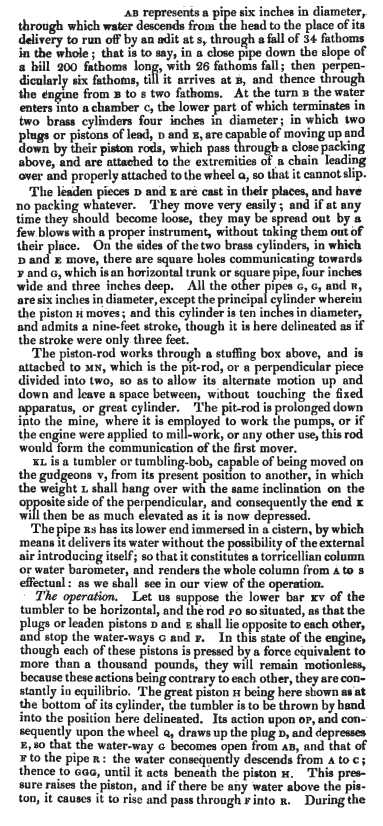
This water-powered pump was described by Robert Fludd (an exquisitely apt name) in his book De Naturae Simia Seu Technica Macrocosmi Historia published (in Latin) in 1618. Robert Fludd (1574-1637) was a prominent English Paracelsian physicist, astrologer, and mystic. He was the son of Sir Thomas Fludd, Queen Elizabeth I's treasurer for war in Europe. I found this very early engine in a book by Thomas Ewbank; details below.
Fludd does not claim to have invented this engine; in his book it is gathered with other machines copied from previous authors or viewed on his travels. He studied on the European mainland between 1598 and 1604, and according to Ewbank, travelled in Germany. It will be seen below that Germany was at the forefront of employing water engines for mine pumping, and it is very probable that he saw some such engine there, and the drawing is a depiction of reality rather than just a piece of theorising.
You can read more about Robert Fludd here (external link) but I suspect there are some inaccuracies in the article. It accuses Fludd of putting forward perpetual motion schemes, but this site says the opposite. Not at present having a copy of Fludd's book- nor indeed the ability to read it- I'll have to leave the question there for the time being.
 |
| Left: The Fludd pump: 1618
The remarkable thing about this early engine is that it is self-acting; in other words the valvegear is operated by the engine itself, and not, as in the earliest steam engines, by a man operating valves at appropriate points in the cycle.
Pipe D is the pump suction pipe with a non-return valve at the bottom, and B the delivery pipe with a non-return valve shown next to the little funnel. This funnel with its associated stopcock is used to prime the pump by filling pipe D with water initially. The junction of B and D connects with the pump cylinder, which contains a piston shown by dotted lines.
Power water flows into the pipe A, which would in practice have to be much higher above than engine than shown. It is connected to the power side of the pump piston by a three-way cock and pipe C. With this cock in its initial position, the pressure of water in the upper part of A forces up the piston and the water in the cylinder is pushed up through pipe B, and into the trough. Meanwhile, the spout protruding from pipe A has filled the bucket G sufficiently to make it turn the arm connected to the three-way cock, which now closes the connection with the power water and opens a connection with the lower part of pipe A, which allows the power water to drain from the cylinder, aided by the weight of the piston; note that the lower end of pipe A is below the surface of the standing water, to prevent air entering.
As the piston descends water is drawn up pipe D to refill the cylinder for the next cycle. When bucket G reaches the bottom of its travel, a valve in its underside is operated by a fixed vertical pin and the bucket empties. The counterweight on the other end of the valve arm then returns the three-way cock to its original position and the cycle recommences.
From Descriptive and Historical Account of Hydraulic and Other Machines for Raising water by Thomas Ewbank, 4th edn, pub New York, 1850
|
This engine, according to Ewbank, represents the earliest known application of a pressure piston to generate power. The piston was described as a wooden plug covered with leather and loaded with lead. According to the drawing it has no means of guidance, so it would need to be much longer than the dotted item shown if it was to avoid tilting and jamming in the cylinder.
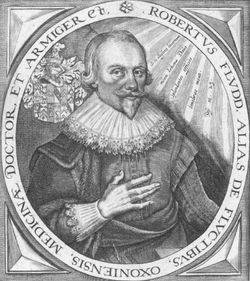 |
| Left: Portrait of Robert Fludd. (1574-1637)
Fludd specified that the power water could be waste or "refuse" water though it would seem that this would be unlikely to be available at a high level. This would have been a really poor idea if the pumped water was intended for drinking, as the piston would not have been completely water-tight. Fludd was of course writing long before it was realised that disease could be spread by contaminated water.
|
Be warned that Googling "Fludd pump" will get you lots of pointless references to the Super Mario Brothers.
BELIDOR AND CO
A suggestion for a positive-displacement water engine was made by Bélidor in his famous book Architecture Hydraulique, published in 1739. He mentions that a water-pressure engine had been built in 1731 by MM Denisard and Duaille; the water supply had a head of only 9 feet, and a 1/24 quantity of the power water was raised to 32 feet. [Weisbach]
To put this in perspective, Thomas Newcomen built his first atmospheric steam engine nearly twenty years earlier at a coalmine in 1712, taking out a patent as early as 1705; by the time of his death in 1729 there were at least one hundred of his engines in Britain and across Europe. The Newcomen machine was the first steam engine to make use of a piston fitting in a cylinder, and even the crude version it used tested the contemporary technology to the limit.
On earlier versions of this page I wrote "This makes it clear that the water engine was derived from the steam engine, and not vice versa.", but the discovery of the Robert Fludd engine above throws the question open. Did Newcomen get the idea of a piston in a cylinder from Fludd? Fludd's book was published in Latin, and Newcomen started his career as an ironmonger; it seems unlikely that it would have been accessible to him. It seems more likely he was inspired by the steam cylinder and piston of Denis Papin (external link) who is usually regarded as the forefather of the steam engine.
THE WINTERSCHMIDT WATER ENGINE
According to Weisbach, the first use of a water engine for mine drainage was by someone called Winterschmidt, though this is questionable in the light of Robert Fludd's description above. A drawing and description of Winterschmidt's engine is given in Calvor's Historisch Chronolog Nachricht des Mashinenwesens auf dem Oberharze published at Braunschweig, Saxony in 1763. Oberharz is a Samtgemeinde ("collective municipality") in Lower Saxony, Germany; its chief town is Clausthal-Zellerfeld.
THE HŚLL WATER ENGINE
A water-engine pump was built in 1749 by Hśll at the mines at Schemnitz in Hungary. Others were later built in various parts of Germany. There were however problems in finding people able to work to the tolerances required for construction and maintenance, and the engines proved uneconomic. In these engines the energy supplied was calculated as: water quantity x head. On this basis the efficiency of the Hśll engines was in the range 33% to 46%, though one was reported to have reached 52%.
Hśll's engine is described in Delius' Introduction to Mining published at Vienna in 1773.
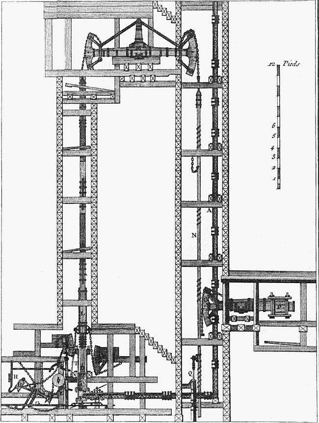 |
| Hśll's water engine: 1749
The power water descended the pipe A on the right of the drawing, and was then fed horizontally to the cylinder T at lower left. This pushed up the piston, causing the rocking beam M to lower the pump-rod N, operating a pump at R,Q. When the water was released from the cylinder, the weight of piston and piston rod pulled the pump rod back up. Note there is also a balance-weight P at extreme right. The Heath-Robinson-looking machinery around the cylinder is the valvegear required to make the engine self-acting; how it worked is obscure.
This is a single-acting engine, the water acting only on the lower side of the piston.
The position of the pump means that this engine must have been at the bottom of the shaft, as water can only be raised some 28 feet or less by suction. This reduces the weight and expense of the pump-rod, but it does mean that the exhaust water has to be pumped back out of the mine.
From Stronger Than A Hundred Men by Terry S Reynolds. Pub John Hopkins University Press 1983
|
Both Winterschmidt and Hśll's engine were described in Busse's Betrachtung der Winterschmidt und Hśll'schen Wassersaulenmaschine etc published at Freiberg in 1804.
RICHARD TREVITHICK & HIS WATER ENGINES
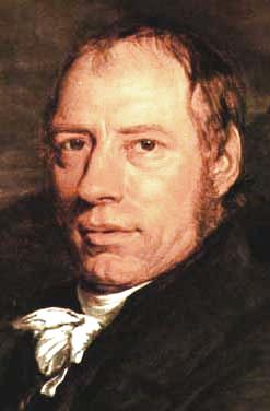 |
| Left: Richard Trevithick 1771-1833
The great Richard Trevithick, famous for using high pressure steam, also built hydraulic engines in Cornwall, the best known being at the Wheal Druid copper mine near Truro, Cornwall around 1793; it was said by Julius Weisbach in his book Principles of the Mechanics of Machinery to be still at work; since however Mason's english edition of 1849 does not give the date of the original book the date referred to is uncertain.
|
Further information is given in A Treatise of Mechanics by Olinthus Gregory. (p311, Vol 2, 4th edn 1826) Gregory says that Trevithick erected a pressure engine "20 years ago" which could mean 1806, but it is more likely that that part of the text had not been revised since the first edition, which is currently of unknown date. The engine was erected, as we have seen, at the Druid copper mine, in the parish of Illorgan, near Truro. The power water was supplied through a pipe six inches in diameter, with a head of 34 fathoms (204 feet).
Here is the full text of Gregory's description of Trevithick's Druid engine:
Towards the end the author makes the very important point that since water is effectively incompressible, if the inlet valve closes before the exhaust valve opens, the engine will judder to a halt, and momentum cannot be used to keep things moving until the exhaust valve is activated, as it can with steam. This is why the valvegear of many water engines looks rather complicated.
For a long time the diagram of the engine (Plate XXIII at the end of the book) was missing from this page because it was missing from the only copy of A Treatise of Mechanics that I had access to. Now, through the kindness of C Kurtz, here it is:
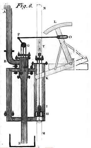 |
| Left: Richard Trevithick's water engine
The piston in the power cylinder is H, and the power output is taken through the pit-rod N. As the rod rose and fell blocks of wood I and T attached to it moved the "tumbler" L which, via P and Q, operated two plug-valves D which controlled the flow of water in and out of each side of the piston. The exhaust water flowed away through pipe S.
The operation is explained in much more detail in the text reproduced above.
|
The following information comes from Richard Trevithick: Giant of Steam by Anthony Burton, p57. Pub Aurum Press 2000.
Trevithick's first water engine was erected at Roskear in Mid-west Cornwall, where there was a reliable water supply from a tributary of the Red River; the operating head is so far not known to me. Water entered the bottom of the engine cylinder and raised the pump-actuating pole; when the water was released the pole fell under its own weight. It had no beam and resembled the Reichenbach pumps dealt with below, except that it was single-acting instead of double-acting.
The Wheal Druid engine appears to have been his second design; it was a much more sophisticated machine, with a more complex valve-gear designed to minimise water-hammer. Trevithick went on to supply water engines for the Alport lead mines in Derbyshire, but he had considerable trouble in getting paid, and this is what he had to say about the Derbyshire mine owners:
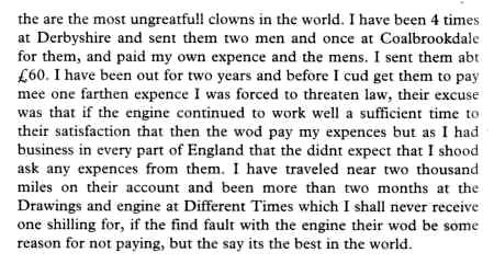 |
| Note that as far as Trevithick was concerned, "they" was spelt "the".
Extract from a letter to Davies Gilbert, 10th January 1805.
|
Water engines were not extensively used in Cornwall, partly because there were few suitable sources of water, but water engines remained popular in Alport for many years.
According to Burton, a picture of the Wheal Druid engine can be found in "an old encyclopaedia". This is probably a reference to the book by Olinthus Gregory, but that is speculation on my part.
THE REICHENBACH BRINE PUMPS
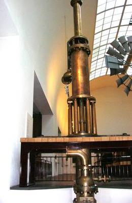 |
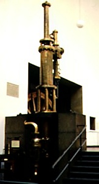
| Left: One of the Reichenbach brine pumps: 1817
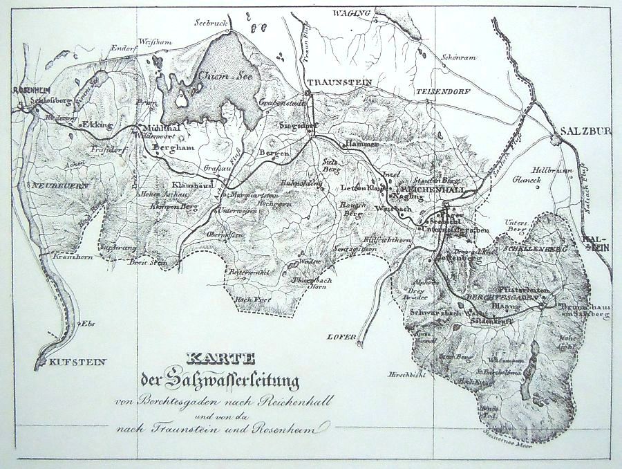
The next installation was by Georg Friedrich von Reichenbach (1771-1826) in the Tyrolean Alps. A total of eleven water engines, some single-acting and some double-acting, were used to pump brine from salt mines at Bad Reichenhall and Berchtesgaden (yes, that place) 18 miles (29 km) to Rosenheim, an area which had sufficient supplies of wood to evaporate the brine and produce crystalline salt. The complex installation was completed in 1817, using wooden pipes. In 1837 Rosenheim produced 200,000 cwt (10,000 tons) of salt per year. The brine system operated constantly until Febuary 1927.
This appears to be the same Georg Reichenbach who in 1791 bribed his way into Boulton and Watt's works on successive nights to make extensive drawings of one of their steam engines. Von Reichenbach is actually much better known as an optical designer than as a mechanical engineer; he was associated with Joseph Fraunhofer, the celebrated inventor of the spectroscope, the diffraction grating, and achromatic lenses.
This original water-powered brine pump is in the Deutsches Museum at Munich in Germany; it was originally installed at the Pfisterleiten pumping station. (see map below) The pump is at the bottom, and above it, mounted on columns, is the power cylinder that forced the pump piston down and pumped the brine uphill. Above it is a smaller auxiliary power cylinder to pull the pump piston back up again.
|
 |
| Left: The Bonn Reichenbach pump again: 1817
The small cylinder to the right of the main one holds the inlet and exhaust valves.
The engine is constructed from brass to better resist corrosion by the salt water.
This is one of the original water-powered brine pumps, in the Deutsches Museum at Munich, Germany.
If you are thinking that the name Reichenbach seems familiar, you are quite right. The Reichenbach Falls were the scene of the famous confrontation between Sherlock Holmes and Moriarty.
|
 |
| Left: The Reichenbach brine-pump in the Deutsches Museum at Munich: 1817
These pumps are very tall and not easy to photograph. Here we are looking up at the valve cylinder, with the engine cylinder on the left. The bolted rectangular fitting in the middle is the port between the valve cylinder and the engine cylinder.
|
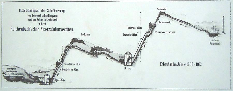 |
| Left: Part of the Reichenbach brine-pumping system: 1817
This section ran between Pfisterleite on the left, pumping brine up to Sudhaus Reichenhall on the right. At the summit you can see the hochreservoir (high reservoir) for the brine, and a little downhill to the left the druckwasserreservoir (driving-water reservoir).
Note the pump at Illsank had to raise the brine by 356 metres. That requires a pressure of 500 psi, which sounds like a lot for wooden pipes; I assume they must have been like tree-trunks with a relatively small hole down the middle. I currently have no information on how the lengths of pipe were joined together.
|
 |
| Left: The Reichenbach brine-pumping system: 1817
The section shown above ran between Pfisterleite and Reichenhall on the right of the map.
LINKS:
Here is a short history of the system.
One of the pump houses is in its original condition, with the pump in place, at Klaushausl. (see left centre of map above)
|
THE JUNCKER WATER ENGINES
 |
| Left: One of the Juncker water engines in Brittany
Some years after the work of von Reichenbach, news of his engine reached M. Juncker, director of the mines of Poullaouen and Huelgoat in Brittany, was in the process of planning water engines to drain them. Having travelled to Bavaria, he returned and built two impressive water engines. Each engine had a vertical cylinder 3.37 ft in diameter and 9.02 ft high, and made 5.5 strokes of 7.54 ft per minute, driven by a water head of 243 ft. The pump rod passed through the base of the cylinder, and ran down to a pump in a pit sump 1080 ft below ground level; it weighed 35,287 lbs. The water was actually only raised 754 ft where it ran into an underground discharge gallery. This gallery was 46 ft above the position of the engines, so the exhaust water had to make its way up to this level; the effective head for running the engines was therefore reduced to 197 ft. The inlet and exhaust valves were arranged to open and close gradually to prevent concussion and water-hammer. Juncker estimated that efficiency would be 65% at full load.
Information in the paragraph above is from "A Treatise on Hydraulics for the Use of Engineers" by J F d'Aubuisson de Voisins, translated by Joseph Bennett and published by Little, Brown and Co of Boston in 1852.
The Juncker engines were described in detail by William Rankine, in his book The Steam Engine, apparently drawing on an account written by someone called Delauney.
In the picture at left it can be seen that the engine is single-acting; water pressure pushes up the piston A, but the weight of the pump rod pulls it down again. B is the cylinder, with piston A near the bottom of its stroke. The piston is attached to the pump rod which passes through a stuffing-box in the base of the cylinder. Water enters and leaves the cylinder through passage D, controlled by piston-valve E.
C is the water supply pipe, with throttle valve U. G is the exhaust pipe, with throttle valve V; why the exhaust should need a throttle valve as well as the supply is not at present clear.
Image from The Steam Engine, by Prof William Rankine 1888, p140.
|
 |
| Left: The valve gear of the Juncker water engine
The edges of valve E are notched so that opening and closing is gradual to reduce shock. F is a trunk piston which operates valve E; when water is admitted through port I, piston F is pushed down. This practice of working the main valves with an auxiliary water-engine is one we shall see again and again as the history of the water engine unfolds, though the reason for its adoption is not always clear.
H is the supply pipe and M the discharge pipe of the auxiliary engine, which has its own piston valve at K. The plunger L has the same piston area as K, balancing the forces so K does not tend to move up or down under water pressure.
Referring back to the drawing above, N is a vertical tappet rod attached to the back of the main piston A. It carries tappets X and Y which engage with the crutch P and operate the auxiliary piston valve K through the linkwork O Q R S T.
H and M, the supply and discharge pipe of the auxiliary engine, are fitted with cocks which can be used to control the speed of the whole engine; this raises the question of just what the two throttle valves U,V are for.
There is also the question of why an auxiliary water-engine was used to operate the main valves. If the engine could lift a 35,287 lb pump rod then there was obviously no lack of power available to operate valves. Possibly the answer lies in the need to operate the main valves slowly to control water hammer.
From The Steam Engine, by Prof William Rankine 1888, p141.
|
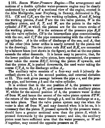
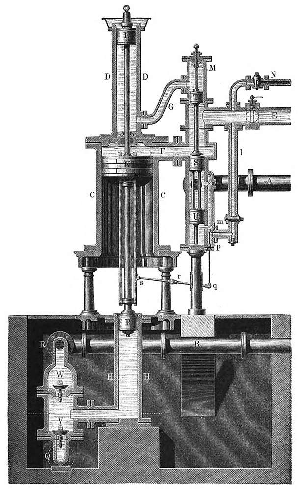
THE FREYBURG WATER ENGINE
A two-cylinder water engine was erected at Alte Mordgrube, near Freyberg in Saxony, at a date which is currently unclear, but was certainly before- probably well before- 1849. This engine worked from a head of 356 feet, and had cylinders 18 inches in diameter, with a stroke of 8 feet. It made 4 double strokes per minute. The wooden beams that serve as piston rods were connected by a pivoted beam so one went up as the other went down; presumably this was connected in some way to a pump rod running down the mine shaft, but no details of how this was done have so far been uncovered.
 |
| Left: The Freyberg water engine
The two cylinders are shown with the valve system between them. E is the power water inlet into the valve cylinder.
S and T are the two valve pistons. W is the auxiliary piston.
The valve piston is shown here in its lower position, and water is pushing up the piston on the right.
The position of the valve piston is controlled by auxiliary valves, in a manner very similiar to the Juncker water engines. The valves are shown in section at I, and in external elevation at II.
I'm afraid the image quality is not all it might be, but then it does come from a very old book.
From Principles of the Mechanics of Machinery and Engineering by Julius Ludwig Weisbach, ed by Walter Johnson 1849. (PDF p619)Water engine chapter p298-p341 (PDF p583-670)
|
 |
| Left: The Operation of the Freyberg water engine
Like so many early descriptions of the operation of machinery, this one is rather long-winded. However I am afraid I have shrunk from the task of editing it down, so here it is in its entirety.
From Principles of the Mechanics of Machinery and Engineering by Julius Ludwig Weisbach, ed by Walter Johnson 1849. (PDF p618) Water engine chapter p298-p341 (PDF p583-670)
|
 |
| Left: The Operation of the Freyberg water engine
The rest of the text.
From Principles of the Mechanics of Machinery and Engineering by Julius Ludwig Weisbach, ed by Walter Johnson 1849. (PDF p622) Water engine chapter p298-p341 (PDF p583-670)
|
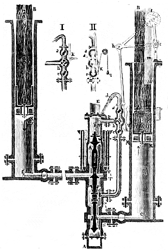
THE WEISBACH WATER ENGINE: 1855
 |
| Left: Illustration of a water engine by Julius Weisbach: 1855
From Die Experimental-Hydraulik by Julius Ludwig Weisbach, published by J G Engelhardt in 1855. I have not yet come across an english translation of this book, so I cannot be certain, but this appears to be a representation of the Reichenbach brine pumps, described above.
A single-acting engine is shown here. Water is admitted above the power piston K through the port Fand forces down the much smaller pump piston P. The pump cylinder is H, and the inlet and delivery valves are V and W respectively. The small cylinder D has an auxiliary power piston L that pulls P back up, and readies it for the next downward pumping stroke.
|