The Dolgorouki Rotary Steam Engine

New page: 15 July 2008

Updated 8 Dec 2019

Comments from Bernd F added

I have settled on the spelling 'Dolgorouky'
Back to Home PageBack to The Museum EntranceBack to The Rotary Steam Engine Wing

Dolgorouky Engine pic from Nature
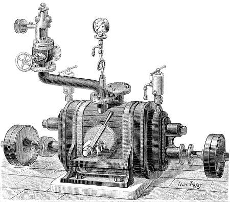
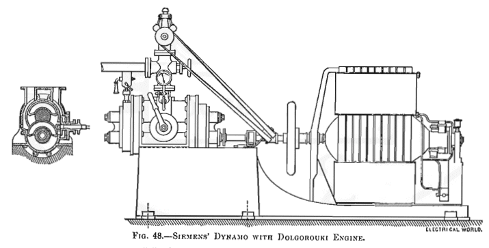
Left: The Dolgorouky Engine.

According to Nature, this machine was exhibited at the Exposition Internationale d'Electricité, in both the Russian and the German sections; in the latter it was on the stand of the Siemens & Halske company, where it was running a direct-current dynamo. The example on display (shown here) was destined for the Lichterfelde tramway, in Berlin, the world's first electrical tramway.

The engine had two pairs of semi-cylindrical rotors, synchronised by spur gearing at each end of the casing. It was noted that it had no dead-centre points. There is a centrifugal governor in the steam inlet pipe at top left. The lever on the side is a cut-off control, giving full admission for startup with no dead center problems, or 1/3 cutoff for economical running.

The steam exhaust is the blanked-off flange just behind the inlet pipe.

Image & info from the French journal Nature 1882/1, p155

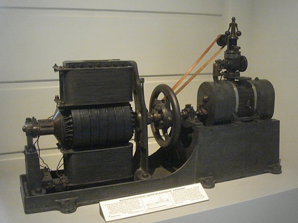
Pictures of real rotary engines that are still in existence are unfortunately very rare. I am therefore very glad to report that I have just discovered a Dolgorouky Engine in the Vienna Technological Museum.
Dolgorouky Engine photo
Left: Dolgorouky Engine at Vienna.

This engine is not the one in the drawing above. It is approximately half the size, and the engine-dynamo combination was put together by Siemens & Halske in 1883 to power the first ever electrical passenger train in 1879. The dynamo output was 20 Amps.

There is a flywheel, but quite a modest one compared with other rotary engines; the dynamo armature would naturally add to the flywheel effect. According to the description in front of the baseplate, the engine gave 5 to 6 horsepower at 900 to 1000 rpm, which is a much faster speed than any reciprocating engine would run at, and much better suited for direct coupling to a generator.

The engine casing is about 14 inches long.

Author's photo July 2008

Dolgorouky Engine photo
Left: Dolgorouky Engine at Vienna

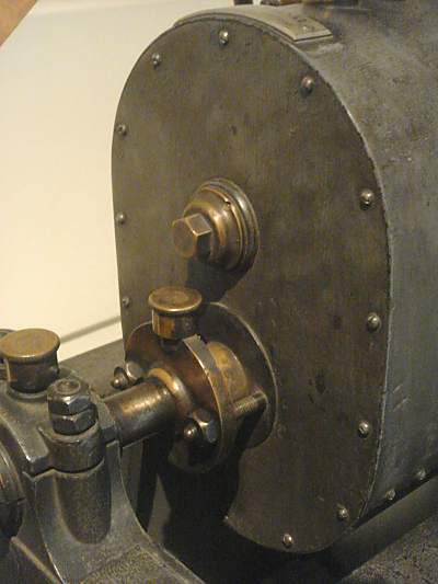
A close-up of the left-hand end of the engine.

Author's photo July 2008

Dolgorouky Engine drawing
Left: Dolgorouky Engine at Vienna

Photo of the label in front of the displayed engine.

Author's photo July 2008

Dolgorouky Engine drawing
Left: Dolgorouky Engine at Vienna.

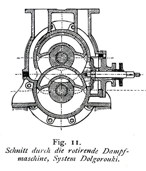
A close-up of the engine cross-section, which gives some clue to the internal construction. It appears to be very similar to the Behrens engine of 1886, having two C-shaped rotors turning around fixed centres. The Behrens engine has the advantage that it avoids the usual rotary engine error of line-contacts between rotor and casing that make sealing virtually impossible, and it looks like the Dolgorouky also used one of the more promising engine geometries.

To the right is a valve that controlled the steam cutoff, giving full admission or 30% cutoff.

Image courtesy of Bernd F.

Dolgorouki Engine dwg
Left: Dolgorouky Engine at Vienna.

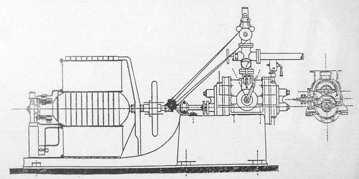
This appears to be original drawing of the engine-dynamo combination. Note the absence of dotted lines.

Taken from The Electric Motor and Its Applications by T. C. Martin And Joseph Wetzler, Third Edition. Figure 48.

Apparently the drawing was first done for Electrical World, a journal published in New York.


THE BERLIN PATENT

Dolgorouky Engine patent
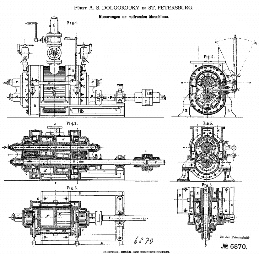
Left: Diagram of the engine from the German patent: 1879

Dolgorouky took out patents for his engine in France, Italy, Britain, Germany, Belgium, and Austro-Hungary. This must have been expensive, but presumably for a Russian prince money was plentiful; it certainly shows he had faith in his invention. It is surprising he did not take out a USA patent.

This diagram shows many minor differences from the Vienna engine, but the basic principle of two C-shaped rotors is clear. The two rotors are synchronised by spur gearing at each end of the engine. The small lever is the steam throttle, and the large lever R controls the steam admission cutoff, rather than a small handle on the side of the engine.

From German patent DE6870.


MORE INFORMATION ON THE DOLGOROUKY ENGINE

The following analysis of the Dolgorouky engine is the work of my good friend Bernd F. It is derived from a book called: Elektrische Schienenfahrzeuge in Glasers Annalen 1879 - 1908, copyright Steiger Verlag, Solingen, 1990 It is a licensed re-edition of an original by transpress VEB Verlag für Verkehrswesen. It contains info on tests conducted by Adolf Slaby, who today is better known as one of the pioneers of radio. Slaby was personally supported in his private research by Siemens.

"Further research revealed a surviving specimen in the Vienna Technological Museum and an article by Dr. Werner Siemens in the railway technlogy journal Glasers Annalen, August 1, 1881. The engine had two pairs of semi-cylindrical rotors in 2 chambers, synchronised by gearing in the two end casings. There is a centrifugal governor in the steam inlet pipe at top left. The lever on the front turns a disc valve to allow full admission for startup with no dead center problems or 1/3 cutoff for more economical running. The position of the steam exhaust appears to be the blanked-off flange just behind the inlet pipe."

"This engine is not the one in the drawing above. It is approximately half the size, and the engine-dynamo combination is apparently from a production run by Siemens & Halske. It looks like the drawing published by Siemens in the 1881 article (and possibly on other occasions), plus some thermal lagging around the gearboxes which double as steam chests in cutoff mode. According to the description in front of the baseplate, this one was made in 1883 and used to power some lights. The engine gave 5 to 6 horsepower at 900 to 1000 rpm, which is a much faster speed than any reciprocating engine would run at, and much better suited for direct coupling to a generator. The dynamo output was 20 Amps."


THE INVENTOR: PRINCE ALEXIS DOLGOROUKY

Dolgorouky Engine patent
Left: Reference to Belgian Dolgorouky Engine patent

From the British The Commissioners of Patents Journal, 1879 Volume 2, July to December.

They might have given us the patent number. Here the name is spelled A S Dolgorouky.

Dolgorouky Engine patent
Left: Reference to Belgian Dolgorouki Engine patent

Here we learn that inventor was, as I suspected, Prince Alexis Sergueevitch Dolgorouky, a Russian nobleman, based in St Petersburg. I am not all sure the middle name is spelled correctly there. Bernd F suggests that Alexis Sergeyevitch Dolgorouky is the best transliteration.

From the British The Commissioners of Patents Journal, 1879 Volume 2, July to December.

Dolgorouky portrait
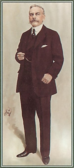
Left: Prince Alexis Dolgorouky: 1846-1915

This is now a rare case where we know quite a bit about the inventor of a rotary engine. See here.

Dolgorouky married the English socialite Frances "Fanny" Fleetwood Wilson. (1850 - 1919)

Dolgorouky was awarded a number of patents in different countries, including German patent DE6870 (C) 'Improvements in Rotary Machinery) dated 1879-08-22, where he is stated as being based in St Petersburg.

There is more information here. He is buried at Hitcham. Unfortunately none of these links make any reference to engine design or even an interest in technical subjects.

Back to Home PageBack to The Museum EntranceBack to The Rotary Steam Engine WingTop of this page