 |
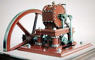
| Left: The Stewart engine: 1850
This engine was introduced by James A Stewart in 1850. It was described in Scientific American Vol. 6, (Nov. 9, 1850), p. 157. The meshing-gear construction is the same as some of the very earliest rotary engines; see especially the Murdoch engine.
Here is some of its history:
"Despite all counsel, efforts to develop the rotary engine continued. One persistent inventor was James A. Stewart of Cross Plains, Tennessee, who patented his rotary engine in 1841 and the following year had the firm of R. M. Roe and Company of New York City build a prototype. This engine was used for a short time in their shops, and Stewart was encouraged enough that he continued to try to perfect its details. About 1848 he made an engine of adequate power to operate a sawmill a few miles north of Nashville. The success of this engine led him to travel to St. Louis where the Eagle Foundry of Clark, Renfrew and Company manufactured these engines for general sale. The design of his engine was simple. Two cog wheels of long axis were enclosed in a tight-fitting iron jacket. Steam was introduced perpendicularly to the axes of the two wheels—the only moving parts—and along the line where they meshed. Except for Babbitt metal lining of the pillow blocks which carried the wheels,46 the engine was built of iron throughout."
"Despite persistent claims over a period of five years by Stewart and by his supporters that his engine had at last been perfected, it never was. Finally in 1853 he decided, as he said, "to abandon any further attempts to introduce my plan of rotary engine." He was prepared to admit that "an attempt to excel, materially, the reciprocating engine, in point of economy, by substituting a rotary, is chimerical." He persisted, nevertheless, in his belief that his principles were sound even though they failed in practice. The major faults of his engine were "its liability to derangement by expansion and contraction of metal, and the yielding or displacement of adjusting screws employed in maintaining the steam wheels in their proper position." Discouraged, Stewart moved to Texas and entered the business of flour milling."
|
From Early Stationary Steam Engines in America by Carroll W Pursell Jr, Smithsonian Institution Press, City of Washington, 1969
|
SIMPSON & SHIPTON'S SECOND ENGINE: 1851
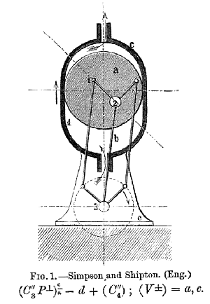 |
| Left: Simplified diagram of the second Simpson & Shipton engine.
This intriguing engine was introduced by two Manchester engineers, Joseph Simpson and James Alfred Shipton. It should not be confused with a similar machine that was patented by them in 1848; see Page 2.
Here it can be seen that the rotor a rotates around an axle 2, which is fixed to the arm b, which pivots around the central axis of the crankshaft 3. The other two arms are attached to cranks set at 90 degrees to each other on the crankshaft, and transmit the rotation of the rotor to it.
This engine was shown driving textile machinery at the London Great Exhibition of 1851, and "attracted no little attention" according to Reuleaux. It was driving cotton machinery supplied by Parr, Curtis & Madeley of Manchester, and by Masons of Rochdale. (The Self Site brings you the details)
But he also said: "In the form before us, however, the machine is in the highest degree impractical, in no respect as advantageous as the common direct-acting engine."
|
 |
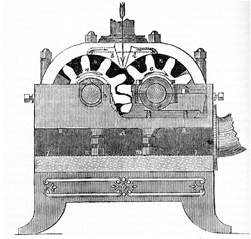
| Left: Side view of the second Simpson & Shipton engine, with the cylinder part-sectioned.
Note the heavy flywheel to the left, more than twice as big as the engine.
|
 |
| Left: Section of the second Simpson & Shipton engine.
g is the eccentic driving the valvegear.
This simplified section does not make the modus operandi any clearer. (to me, anyway)
From "The Steam Engine- Its History & Mechanism" by Robert Scott Burn,
|
 |
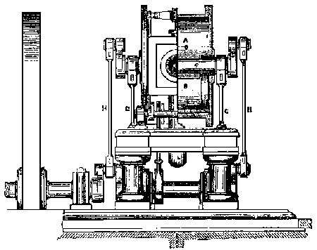
| Left: End view of the second Simpson & Shipton engine.
The slide valves are driven by the eccentric, via a bellcrank on layshaft Z at the left. Note once again that enormous flywheel; did this engine have particularily variable torque in its cycle?
It is very clear is that the number of moving parts is not much less than a conventional steam engine.
|
 |
| Left: Animation of the Simpson & Shipton rotary steam engine.
Here it can be seen clearly how the axle of the rotor slides back and forth in the slot on the side of the casing, allowing rotation. It is also very clear that there is a line contact between the rotor and the inside of the casing, one that looks particularly difficult to seal, as the line contact is not in a fixed position on either rotor or casing.
While it is not readily visible here, the horizontal slot is actually an arc of a circle centred on the crankshaft.
This superb animation is kindly provided by Bill Todd
|
The Simpson & Shipton engine is one of the few engines for which detailed drawings exist. And even better, you can build your own!

THE NAPIER ROTARY ENGINE: 1851
|
| Left: The Napier Rotary Engine: 1851
"An eccentric mounted cylinder on a shaft concentric with the shell. There are two sliding wings in slots in the shell, held to their bearings by springs or cam wheels on the shaft outside with connecting bars. There are two pair of ports."
In the diagram, it appears that on the right side of the two sliding doors, the upper pipe is the steam inlet and the lower is the exhaust. However, in the left part of the casing there appears to be direct communication between the steam inlet and outlet ports, which would hardly be conducive to economy. This could be prevented by the addition of valve gear to cut off the steam admission on the non-working side of the casing, and probably this is what Napier intended. If so, it would detract from the beautiful simplicity that most rotary engine designers aimed for.
Diagram from "Mechanical Movements, Devices and Appliances" Hiscox, 1899
|
According to Reuleaux, this form of engine was first invented by Bahrens of Cologne in 1847; Napier made improvements in 1851, and Bompard of Piedmont reinvented it in 1867.
UNNAMED ROTARY ENGINE: 18??
|
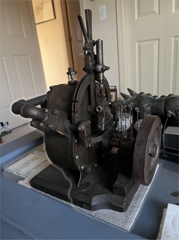
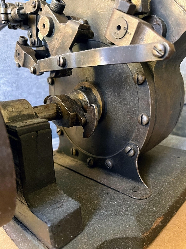
| Left: Unnamed Rotary Engine: 18??
This magnificent piece of rotary machinery is no longer believed to be a Barrows rotary steam engine; it pretty clearly has two rotors inside the casing, and the Barrows engine had only one. See just below.
The engine is reversible, by moving the lever on top. There is a rotary valve for admission and exhaust on each side of the engine, housed in a rectangular box. The valves are driven by a horizontal oscillating bar.
The engine is in private ownership in the USA.
|
|
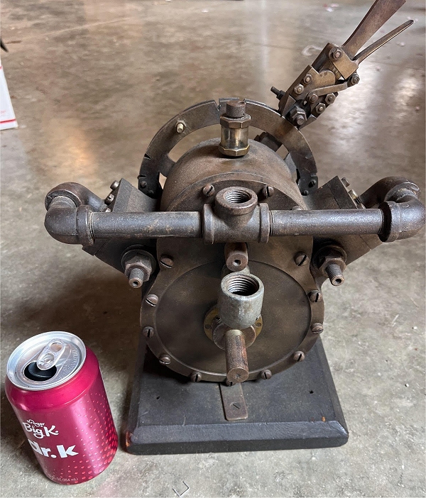
| Left: Unnamed Rotary Engine: 18??
Assuming that's a standard-sized soft drink tin, the engine is not very big, perhaps 300 mm high. The horizontal pipe appears to be the steam inlet, with the exhaust coming out at the front; it is not much bigger than the steam inlet so it is doubtful if much expansion of the steam was occurring.
The small cylinder on top of the engine is almost certainly a lubricator.
The main body of the engine is quite different from that in the Scientific American article below, and I am wondering if this a different design by Barrows or perhaps by someone else entirely.
|
|
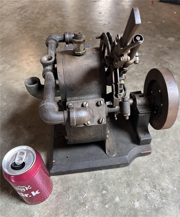
| Left: Unnamed Rotary Engine: 18??
Another view of the engine.
|
|
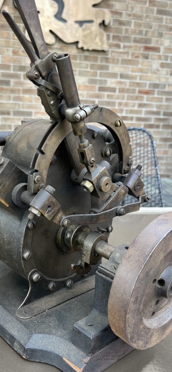
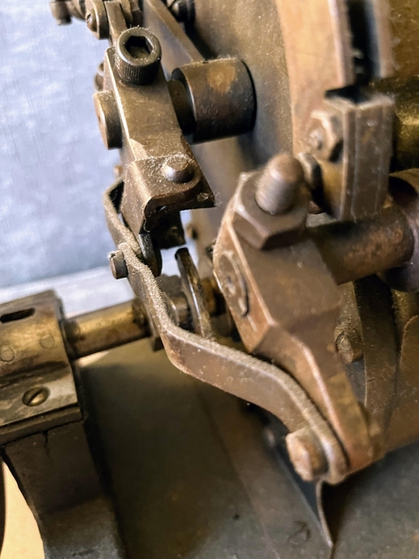
| Left: Unnamed Rotary Engine: 18??
A close-up of the valve gear. The cam attached to the flywheel shaft contacts the thing at the bottom of the hand-lever, causing it to alter the position of the horizontal link that connects the valves. When the hand lever is moved, the phase between the cam and the thing is altered, giving motion in forward and reverse, and stop.
|
|
| Left: Unnamed Rotary Engine: 18??
Another close-up of the valve gear. The curved part on the nose of the cam appears to show some wear, indicating that the engine has been run at some point.
|
|
| Left: Unnamed Rotary Engine: 18??
Another close-up of the valve gear.
|
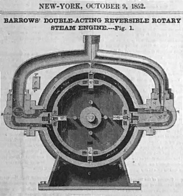
THE BARROWS ROTARY ENGINE: 1852
|
| Left: The Barrows Rotary Engine: 1852
The Barrows rotary steam engine was introduced and patented by Ebenezer Barrows of New York in 1852.
This section of the Barrows engine comes fromScientific American 9 Oct 1852, No 4. It looks like another case of moving abutments, sliding in and out of the central rotor, hopefully in a timely fashion. This was accomplished by grooves in the body engaging with pegs on the abutments. (pistons) Note the rotary valves at each side.
The body of this engine is quite different from the photos above. The photos show a body that looks as if it has intersecting rotors of some kind. perhaps like the Norton Rotary Engine on this page. There are two rotary valves, both handling steam admission and exhaust.
Source: Scientific American 9 Oct 1852, No 4
|
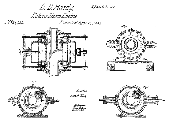
THE HARDY ROTARY ENGINE: 1859
|
| Left: The Hardy Rotary Engine: 1859
The subject of US patent 24,388. There is a single rotating vane with sealing provided by doors that slide out of the way to let the vane pass. The idea goes back to the Bramah & Dickenson Rotary Engine of 1790.
Nothing is known of its history apart from the existence of the patent.
Hardy took out another rotary engine patent (No 77,373) in 1868.
|
|
| Left: The Hardy Rotary Engine: 1859
It appears that the doors were moved in and out by face cams on the plates mounted on either side of the engine casing.
|
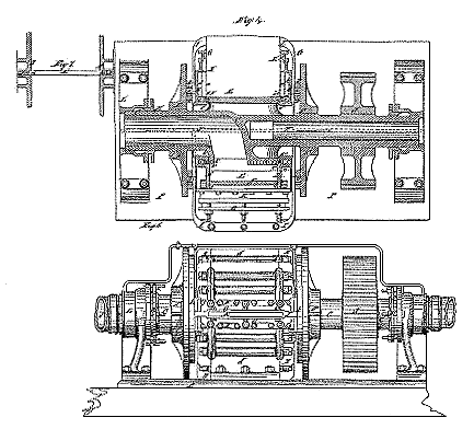
THE MILLER ROTARY ENGINE: 1859
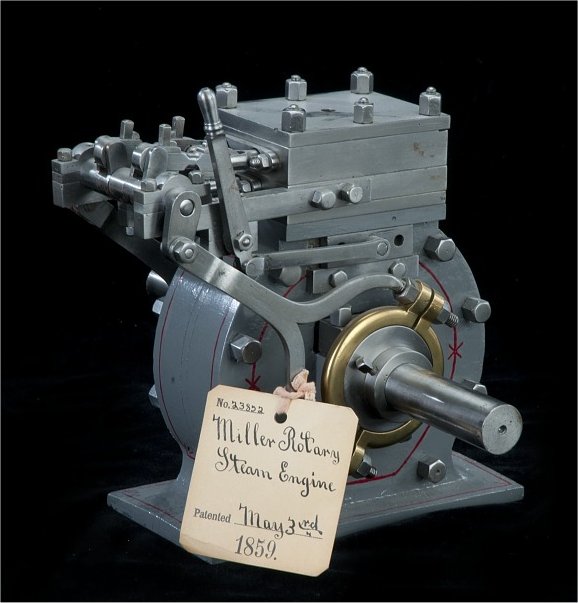 |
| Left: The Miller Rotary Engine: 1859
The US patent system from 1790 to 1880 required a working model to be submitted if you wanted a patent; perhaps this was to slow down a flood of perpetual motion machines.
This model of Miller's rotary engine (US patent 23,852, 3 May 1859, issued to Charles Miller, of Belleville, Illinois) is in the National Museum of American History though currently not on view.
This description comes from the 1939 Catalog of the Mechanical Collections of the Division of Engineering United States Museum Bulletin 173 by Frank A. Taylor:
"The engine has two oval pistons or cams each running in a separate circular cylinder or casing. Sliding abutments in the casing bearing on the edges of the cams direct the steam in the forward direction around the casing. Admission of steam is controlled by two flat slide valves working in steam chests on top of the casing. The valves are operated by two eccentrics on the engine shaft. The engine is reversible."
|
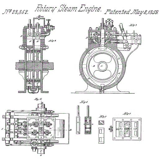 |
| Left: The Miller Rotary Engine: 1859
There are two elliptical rotors set at 90 degrees, (for more even torque) each having a vertical slide E and E', which bears on the top of the rotor. The sealing of this and the tips of the rotors that contact the inside of the cylinder will not be easy to seal.
From US patent 23,852 dated 3 May 1859
|
 |
| Left: The Miller Rotary Engine: 1859
At top is an external view of the engine, showing one of the eccentrics and the reversing lever.
Below are two views of one of the elliptical rotors, with packing pieces at the tips.
From US patent 23,852 dated 3 May 1859
|
THE HOLMES ROTARY ENGINE: 1860
|
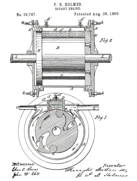
| Left: The Holmes Rotary Engine: 1860
The subject of US patent No 29,787 by Perry Holmes of Cincinnati, Ohio. There is an eccentric rotor with two hinged doors attached. Note the packing at D, adjusted by two screws. You know my methods, Watson.
Nothing is known of its history apart from the existence of the patent.
|
THE MASSIE ROTARY ENGINE: 1864
|
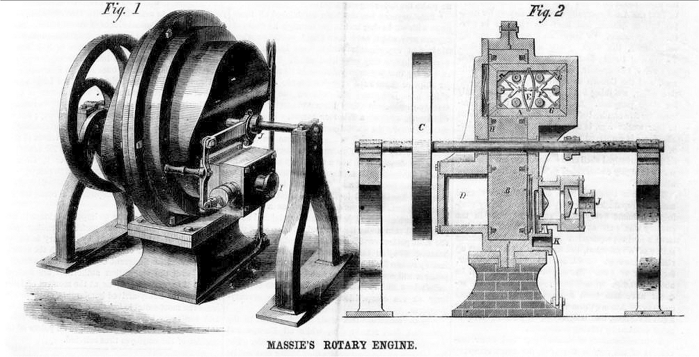
| Left: The Massie Rotary Engine: 1860
There is a sliding piston A set in the rotor B. The piston pushes on the shaped side of the casing D and turns the rotor. The piston is made up of wedges pressed outwards by springs. Steam entrs at J and exhausts at K. It was invented by T G Massie of Port Henry, NY; a patent was said to be pending, but none has been found.
Nothing is known of its history apart from the existence of the Scientific American article. It is otherwise unknown to Google, and clearly not a success.
Source: Scientific American 13 August 1864
|
THE THOMSON ROTARY ENGINE: 1865
This engine was described in a report in The Engineer of an address to the British Association by R W Thomson, CE, FRSE, of Edinburgh. He was not a lone obsessive but a much-respected engineer and acknowledged as the inventor of the fountain pen, and the original inventor of the pneumatic tyre.
He had this to say about the sliding or swinging abutments that plagued many rotary engines: "...the mechanical difficulties arising from the extreme rapidity of movement are quite fatal." I absolutely agree; inventors seem to have been full of confidence that they could make the parts of an engine dodge very rapidly around stops or abutments without leaking steam in the process.
There are some biographical details about R W Thomson in Wikipedia, where he is credited with inventing 'the elliptical rotary engine' which does not describe the engine here at all; it must have a cylindrical bore if the vanes are to move. This might be a reference to the unusual gearing, which looks as if it might be elliptical. It is stated that he made his first model engine at the age of 17.
|
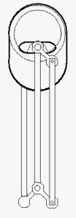
| Left: Skeleton wooden model of the Thomson Rotary Engine: 1865
The Thomson engine is a pursuing-piston or cat-and-mouse engine. The non-circular gears cause the sector-shaped vanes to accelerate and decelerate as they go round, so that the spaces between them expand and contract; steam is applied appropriately so it expands in the expanding spaces. There are no unsealable line contacts so the design was in with a chance.
Thomson claimed the engine was easily reversible, but admitted it did not give a variable cutoff unless "some further appliances" were added.
Thomson concluded his talk thus:
"I have here in Birmingham a portable engine, which will be operation during this and the following days at the works of Messrs Street, where those of you desirous to see it at work will have the opportunity of doing so."
Which does seem to prove that at least a prototype was built and tested.
From The Engineer for 27 Oct 1865
|
This is the first pursuing-piston rotary steam engine to come to the attention of The Museum. There was a later design by Stocker, in 1872 and another at a yet later date by Charles Parsons of turbine fame. (I should move the Parsons, because it's not really a vibratory engine) At least two IC pursuing-piston engines were put forward.
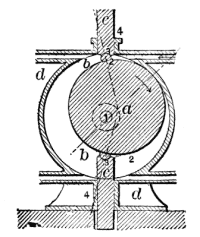
THE NORTON ROTARY ENGINE: 1866
|
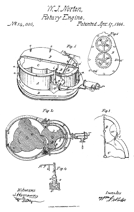
| Left: The Norton Rotary Engine: 1866
The subject of US patent No 54,006. There are two interlocking rotors synchronised by external spur gearing. The engine appears to be reversible.
Nothing is known of its history apart from the existence of the patent.
|
THE GABRIEL ROTARY ENGINE: 1867
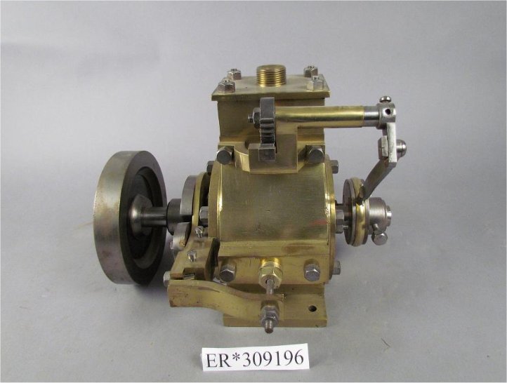 |
| Left: The Gabriel Engine: 1867
This is another model made for the US patent office (see the Miller engine model above) It was submitted with the application for the patent issued to Matthias Gabriel, of Newark, NJ, 6 August 1867; this was US patent 67,527.
This description comes from the 1939 Catalog of the Mechanical Collections of the Division of Engineering United States Museum Bulletin 173 by Frank A. Taylor:
"The engine represented in the model is one of a great many similar designs for rotary steam engines, in which a vane or paddle on a rotary drum fits closely in the annular chamber between the drum and an outer casing and is driven around the chamber by the pressure of steam expanding between the paddle and an abutment that temporarily closes the chamber back of the paddle.
This engine has two sliding abutments, which are moved in (to close the chamber) and out (to clear the paddle as it passes) by means of a cam on the shaft of the engine and a system of followers and yokes. A plain D-slide valve is operated by pinions and rack from an eccentric on the shaft. Two expansions per revolution are obtained."
The sliding abutments do not sound promising.
|
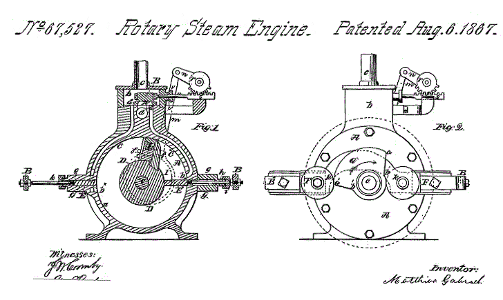 |
| Left: The Gabriel Engine: 1867
The patent drawing shows how it works -or was supposed to work. The slide valve are operated by a small toothed sector, which is rocked by an eccentric on the output shaft. The two sliding abutments are moved in and out by a cam on the output shaft.
From US patent 67,527 of August 1867
|
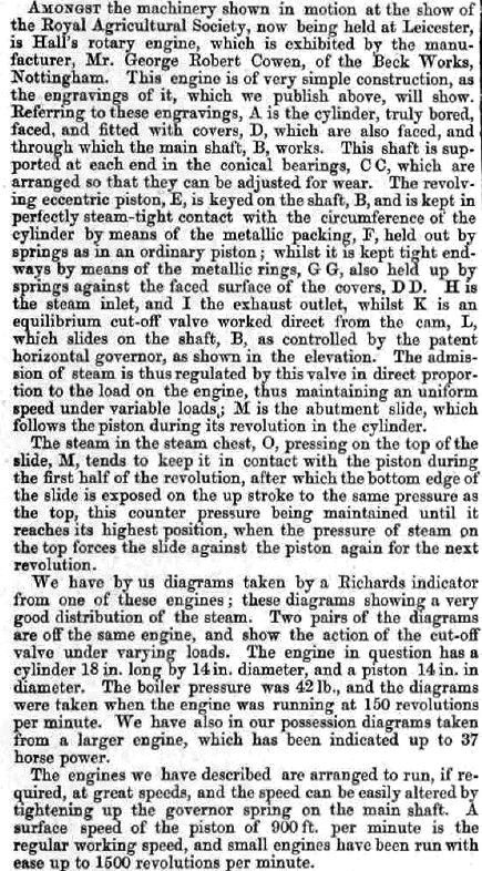
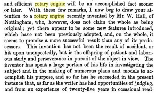
HALL'S ROTARY ENGINE: 1868
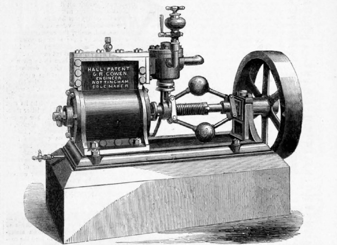 |
| Left: Hall's Rotary Engine: 1868
This engine was shown at the Royal Agricultural Society show in Leicester by its manufacturer, Mr George Cohen of the Beck works at Nottingham.
This engine is perhaps unique in that a large number of models of it have been made, and CAD files can be downloaded, for example from GrabCAD
An odd feature is the large amount of space taken up by the governor.
Apart from a couple of contemporary references, the Hall engine is unknown to Google, and so presumably failed to thrive. There are however many references to making models of it.
Picture from Engineering for 17 July 1868.
|
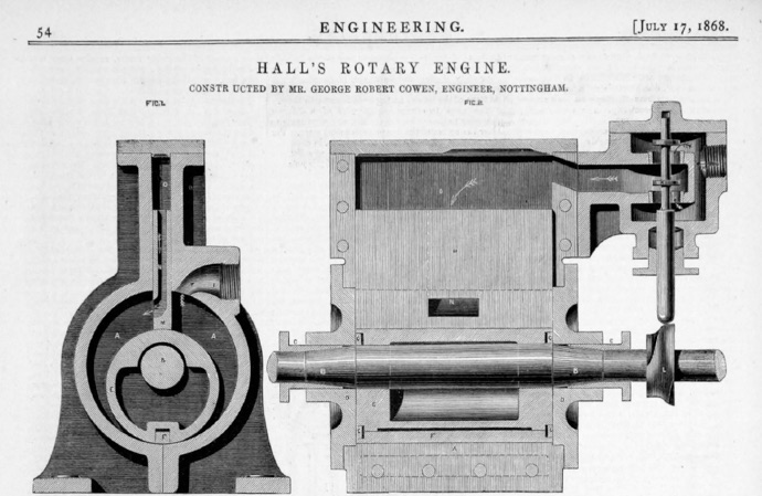 |
| Left: Hall's Rotary Engine: 1868
This engine has a sliding partition at the top of the cylinder, while the rotor is hopefuly sealed by a spring-loaded packing piece F shown here in contact with the bottom the cylinder. How well this sealed is a matter for speculation; leaks here would probably have been enough to doom the engine, though I also have grave doubts about that vertical partition banging up and down.
The steam inlet valve is operated by a cam on the output shaft; this cam is moved sideways by the governor to vary the cutoff and so control the speed.
The parts are labelled with letters but they are very small.
Picture from Engineering for 17 July 1868.
|
 |
| Left: Hall's Rotary Engine: 1868
According to the text at least two engines were built, and probably more.
1500 rpm is very fast for a steam engine.
|
 |
| Left: Hall's Rotary Engine: 1868
From Engineering Facts and Figures edited by Andrew Betts Brown, pubd A Fullerton & Company, 1866.
|
 |
| Left: Hall's Rotary Engine: 1868
Mr G D Hughes is confident that we will eventually come up with a satisfactory rotary steam engine.
From Engineering Facts and Figures edited by Andrew Betts Brown
|
 |
| Left: Hall's Rotary Engine: 1868
Introducing Mr Hall's engine.
From Engineering Facts and Figures edited by Andrew Betts Brown
|
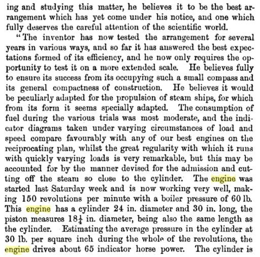 |
| Left: Hall's Rotary Engine: 1868
Here we get some dimensions of the engine, and the information that it first ran on last Saturday week. It is not often that the date of the first trial of a rotary engine can be pinned down to the day.
From Engineering Facts and Figures edited by Andrew Betts Brown
|
 |
| Left: Hall's Rotary Engine: 1868
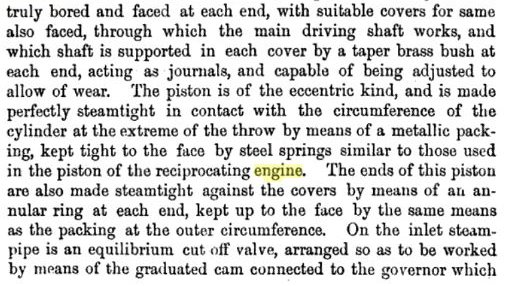
"...the piston is made perfectly steam-tight..." I wonder.
From Engineering Facts and Figures edited by Andrew Betts Brown
|
 |
| Left: Hall's Rotary Engine: 1868
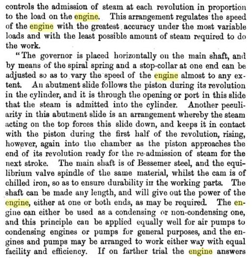
Details of the governor arrangements.
From Engineering Facts and Figures edited by Andrew Betts Brown
|
 |
| Left: Hall's Rotary Engine: 1868
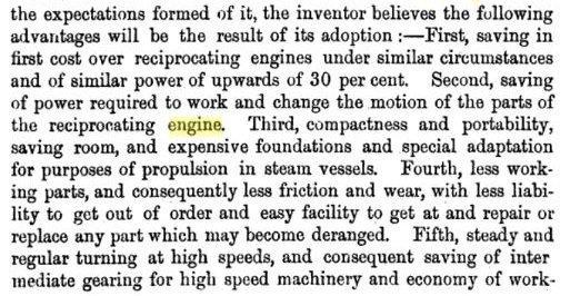
This sounds like the perfect engine...
From Engineering Facts and Figures edited by Andrew Betts Brown
|
 |
| Left: Hall's Rotary Engine: 1868
..and yet not, because none of these claims are factual.
From Engineering Facts and Figures edited by Andrew Betts Brown
|
THE RIKERT ENGINE: 1868
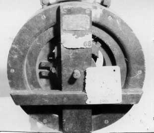 |
| Left: The Rikert Rotary Engine: 1868
Another rare example of a rotary steam engine that apparently still exists.
This engine was invented by Matthias Rikert of Oneida, Knox County; there are more than one Oneida's in the USA, but this appears to be the right one.
Two supporting legs are missing from the engine. (see patent drawing)
Rikert received US patent 76,525 on 7 April 1868, but there is no evidence his engine got beyond a single prototype.
|
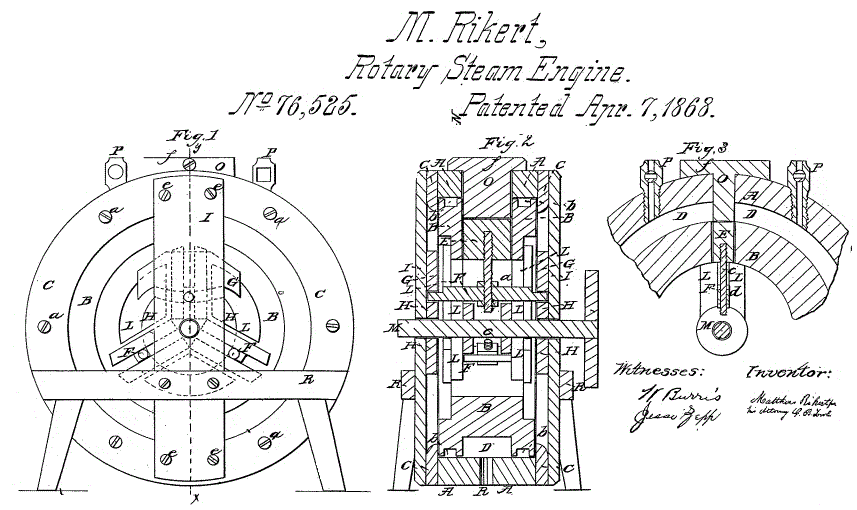 |
| Left: The Rikert Rotary Engine: 1868
The patent reveals the internals of the Rikert engine. There are three vanes on the rotor, which are pulled in to avoid the fixed steam-stop (or abutment) O, by means of pegs F running in a cam channel L in the rotor. This would require miraculous speed and accuracy if it was to be done without steam leakage, and so this design founders at once.
The exhaust port R is at the bottom of the cylinder in Fig 2; it is not very large and seems to allow for little expansion of the steam. Its position indicates that only half of the engine would be doing any work when it was rotating in a given direction.
The patent text includes this statement: "The inner circle will be made steam-tight by metallic packing, and springs suitably
secured in the grooves bb, with set-screws.". Most rotary steam engine patents contain something like this, the use of set-screws implying that continuous adjustment is required to achieve any degree of steam-tightness.
The engine was reversible as either of the (rather small) inlet ports P could be used.
|
ANOTHER HARDY ROTARY ENGINE: 1868
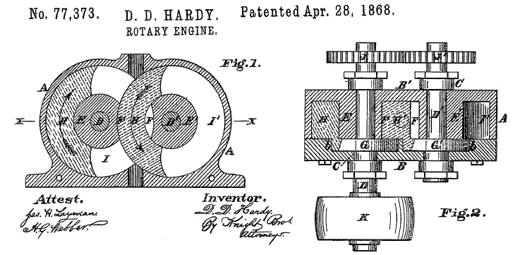 |
| Left: Another Hardy Rotary Engine: 1868
We have seen Mr D D Hardy before, in 1859. This, however, is a completely different design.
|