 |
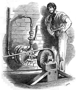
| Left: The Onésiphore Pecqueur engine: 1840.
Virtally all the exhibits in the rotary engine gallery have so far been British or American. Here at last is a French one, devised by the magnificently-named Onésiphore Pecqueur, Chef des Ateliers of the Conservatoire des Arts et Métiers (CNAM) in Paris. Armengaud, in his book Moteur ŕ Vapeur says that the engine was invented in 1825, and brought to "its high point of perfection" in 1839 or 1840. Some of the improvements were introduced by Zambaux and Moret, whoever they were.
Apologies for the wobbly diagram; it was obtained by the Museum staff under difficult circumstances.
Diagram from Moteur a Vapeur by Armengaud, pub 1861, p158
|
I have to say that I think this engine falls somewhat short of a "high point of perfection", although Armengaud says "it is one of the best of its genre.". It is yet another version of the "sliding-door" rotary engine, as put forward by Bramah & Dickenson as early as 1790. The axle B carries a single vane C, which is pushed round by steam pressure. Sliding doors D and D' are moved in and out to let the vane pass, by an external cam H. The cam follower arms are pivoted at G and G'.
Working from Armengaud's book, which says its drawings are to 1/15 scale, the inner diameter of the casing appears to have been something like 30 inches. The power output was between 12 and 15 HP, working with steam at 59 psi, and rotating at a leisurely 80 to 100 rpm. The weight per horsepower was between 30 and 35 kg.
 |
| Left: The Onésiphore Pecqueur engine: 1840.
A section of the engine looking from above, showing the casing A, axle B,and the two sliding doors D and D', which are moved in and out by crossheads E and levers F, driven from the rocking-arms G. The cam H is at the top.
It can be seen that the rotating vane and its corresponding working space have a rather strange two-lobed shape.
Once more, apologies for the wobbly diagram.
Diagram from Moteur ŕ Vapeur by Armengaud, pub 1861, p159
|
While apparently optimistic about the Pecqueur engine, Armengaud then goes on to mention the English Turner engine of 1816, which is in very much the same format as the Pecqueur, with two cam-driven sliding doors. This rather undermines any claims to originality.
BIOGRAPHY
Onésiphore Pecqueur was born in Pas-de-Calais in 1792 and died in Paris in 1852. He is widely credited with inventing and patenting the automobile differential in 1827, having been experimenting with a model of Cugnot's steam carriage; (which is still there in CNAM) I must admit I thought the Chinese had it in 2634 BC, in the form of the famous South-pointing chariot. He invented a new form of net-loom, (for making fishing-nets etc) and patented it in France in 1840, and in England in 1849.

THE UHLER ENGINE: 1840
 |
| Left: The Uhler engine: 1840.
Here is another French engine, invented by M. Uhler, a civil engineer. Armengaud, in Moteur a Vapeur says that Uhler introduced several rotary engines, but this one was "of the perfected system". Despite this perfection, I have found no evidence that it enjoyed any success.
The rotor B is mounted eccentrically on the shaft C, and rotates anti-clockwise, with a swinging "obturateur" E bearing on the rotor by means of a slipper pad b. The inlet port is a hole c (just to the left of shaft C) in the side of the casing A, and is uncovered when it corresponds with the passage g; the length of the curved part f near the shaft determines for what proportion of the cycle steam is admitted; this seems to rule out any variation of cut-off, which is a major drawback. The exhaust ports d allow steam from the part of the casing to the right of the obturateur to escape into the box D, from which it leaves via exhaust pipe G.
There appears to be some sort of seal built into the rotor, just to the right of the passage g.
Diagram from Moteur a Vapeur by Armengaud, pub 1861, p163
|
THE ELIJAH GALLOWAY ENGINE: 1840
 |
| Left: The Elijah Galloway engine: 1840.
There is not much information about this engine, and its mode of operation is unclear. It appears to have an eccentric rotor which goes around inside an inner casing C. The gearwheels E are driven from the centre of the engine but their purpose is obscure.
This has been stated to be Galloway's first rotary engine, but see The Galloway Engine of 1834 on Page 1.
Diagram from Norbye
|
 |
| Left: The Elijah Galloway engine: 1840.
The enigmatic gearwheels E can be seen on each side.
Diagram from Norbye
|
THE BEALE ENGINE: 1835-1862?
 |
| Left: The Beale rotary engine
In this engine the steam enters on one side of an eccentric rotor which carries rollers that (in theory) seal against the inside of the casing. Outward pressure on the rollers was supposed to be generated by centrifugal force; this would seem to guarantee that if the force was adequate at full speed, it would be too low at lower speeds and allow leakage. This is quite apart from the impossibility of making steam-tight the line seals between the rollers and the casing. (The centrifugal principle is used today for pumps but the operation is quite different, and does not depend on sealing between the rotor and the casing) What appear to be sliding vanes running through the centre of the rotor are not intended to control steam flow, but appear to be a means of pushing the rollers outward to give some sort of sealing so the engine can start from rest, where there is no centrifugal force.
The screw-operated valve on the top of the casing allows for stop/start and reversing, but there is no way to alter the admission cutoff, and apparently no expansive use of steam.
According to Bourne, "An engine upon this plan has been put into a steam vessel, but its success has not been such as to induce its more extended adoption." We shall see later that this contradicts several reports of successful voyages.
Image from A Treatise on The Steam Engine in Its Application to Mines,Mills, steam navigation and Railways by the Artizan Society, ed John Bourne, pub 1853 Longmans
|
The known history of this engine appears to begin in 1835 when Joshua Beale took out a patent for it. In 1848 it was referred to by George Stephenson at a meeting. It was also described by John Bourne in 1853. It does not however appear on a list of rotary engines compiled by John Scott Russell which ends in 1836. In view of its long life as a workable engine (to some extent, at least) I have left it here rather than moving it to the page dealing with earlier engines.
George Stephenson, at a Meeting of the Institute of Engineers, stated that he had been concerned in having a trial made of Beale's engine, in a steam boat intended to carry passengers only half a mile, to Yarmouth; but when the engine was put to work he could not make the boat move forward, and so the experiment failed. He managed to get the boat to sea, and it cost him and his party Ł40 to bring her back again.
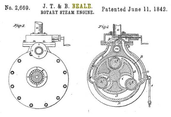 |
| Left: Beale engine end view: 1842
Note the use of ball bearings in the view on the left. The strut on the view to the right seems to be something to do with handling the torque reaction, but the patents is rather obscure on this point.
From US patent No 2,669. 11th June 1842
|
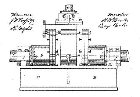 |
| Left: Beale engine side view: 1842
Steam enters through the pipe on the top and exhausts through the pipe at upper left.
One of the patentees is Joshua T Beale, but the other, Benjamin Beale, does not so far appear anywhere else in this story.
From US patent No 2,669. 11th June 1842
|
Here are the known patents referring to the Beale engine:
- No 2,669. 1842, USA
- No 2,090, 1857, British
- No 1,402, 1866, British
- No 2,419, 1877, British
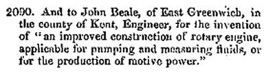 |
| Left: The next generation of Beales
This entry from The London Gazette shows that the 1857 patent was granted to John Beale, son of Joshua Beale.
From The London Gazette August 21, 1857, p2854
|
There may be others; I have discovered a reference to Beale's patent for "Improvements in Steam engines" in the index to Mechanics Magazine for 1841. That is regrettably vague, and the relevant page is missing from my copy. However it does seem to indicate there was a British patent before 1857.
According to Elijah Galloway, a Mr Beale, in partnership with a Mr Beningfield, obtained in 1823 a patent for a very different kind of engine in which the external cylinder revolved but the inner rotor remained stationary. See just below.
(In dealing with British patents it is essential to know that from 1852 (from 1 October) to 1915 patent applications filed were numbered starting anew at 1 each year; granted patent applications retained the same number. Because of this reuse of numbers, it is necessary to specify both the year and the number. When the the patent law was (at last) modernised in 1852, 14,359 patents granted up to that date were given numbers of the form No nnnn/yyyy, eg No 102/1617, No 513/1769 and so on)
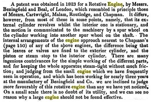 |
| Left: Elijah Galloway on Beale's 1823 patent
It is said here that the engine had been working for three years at Mr Beningfield's factory.
The Chapman engine of 1810 is on the first page of this part of the Museum.
From A History of the Steam Engine: From Its First Invention to the Present Time 18??, p??
|
 |
| Left: A letter enquiring about the Beale engine
A puzzled subscriber to Mechanics Magazine poses some very pertinent questions about the operation of the rollers and the end-sealing system. (It sounds as if there wasn't one)
Unfortunately I do not currently have access to the "November part" he refers to.
From Mechanics Magazine Jan 13, 1844, p23
|
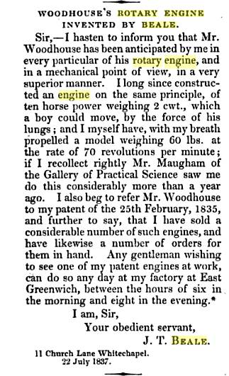 |
| Left: Mr Joshua Beale complains
The Woodhouse engine has now been tracked down by the Museum staff and the whole sordid affair will be revealed here shortly.
I am having trouble believing that any of these engines could be driven by lung-power. I have to say that Bill Todd does not agree with me, and his knowledge of kinematics etc is far superior to mine.
Note that Mr Beale claims to have sold "a considerable number of such engines". Come on, Joshua, exactly how many?
From Mechanics Magazine29 July 1837
|
From the above information, you would conclude that the Beale engine was a complete failure, and Beale himself a deluded man. However, the truth is rather more complex, as it so often is...
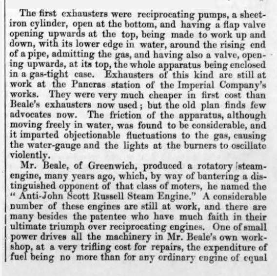 |
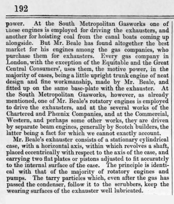
| Left: Mr Beale and his gas exhauster
There were two Beales, the older being Joshua T Beale, the younger John. Joshua Beale was the inventor of the Beale Exhauster, a low-pressure pump that sucked the gas from the retorts of gas-works, and pushed it into the mains. This account from The Engineer in 1952 makes it clear that Beale's exhausters were successful, and some of them were driven by his rotary engine.
The lower paragraph claims that "A considerable number of these engines are still at work" which sounds like some sort of success.
It is fascinating to learn that Beale called his engine the "Anti-John Scott Russell Steam Engine" but it is also puzzling, because according to Mr Onion in a famous meeting Scott Russell had himself written on and patented several Rotary Engines. Presumably Scott Russell had changed his mind and was exhibiting the fervour of the convert.
From The Engineer 28 March 1862, p191
|
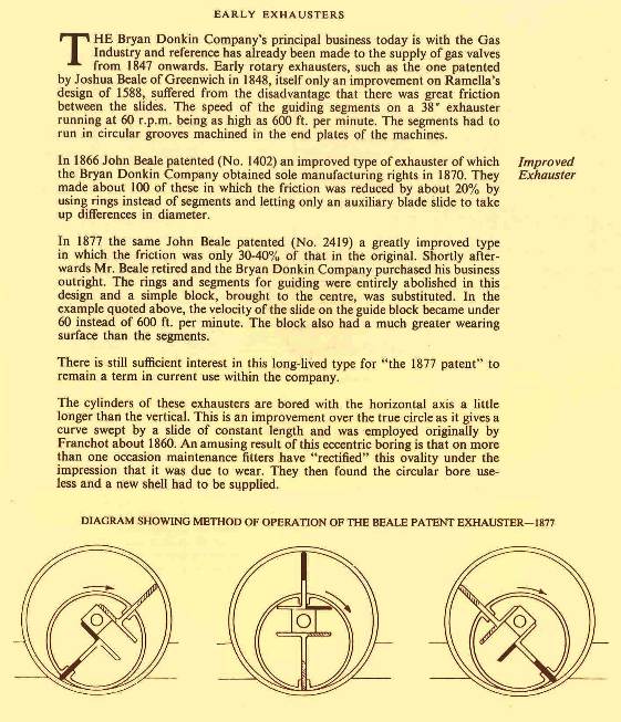 |
| Left: Historical facts on Beale's gas exhausters
Rotary steam engines are very often put forward as equally useful as pumps, but in fact such rotary machines are usually much more successful as pumps than as engines. Here is a case in point- the Beale gas exhauster looks very much like a rotary engine.
Note that the exhauster cylinders were bored out to be oval or elliptical, as described for the The Hyatt Engine below on this page.
Adapted from A Brief Account of Bryan Donkin and of The Company He Founded published by The Bryan Donkin Co Ltd of Chestefield, England.
|
 |
| Left: Beale's gas exhauster animated
Finding the operation of the Beale gas exhauster a bit less than obvious, I persuaded Bill Todd to create another of his stunning animations.
Bill speaks: "The important bit to realise is that the vane is constrained to the elliptical cylinder by the sliding guide, not by the edges of the vane. I'm not really sure how the real thing was constructed: it requires that the rotor be driven from one end of the cylinder, while the guide axis is supported from the other end."
|
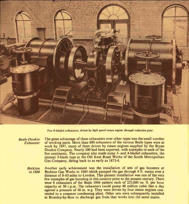 |
| Left: Two Beale-type gas exhausters in situ
In this case they appear to be driven by a high-speed vertical reciprocating steam engine.
In front of each exhauster is a very large vertical valve. The size of these demonstrates how town gas was handled at a low pressure, and so large pipe diameters were required for a given mass flow.
Adapted from A Brief Account of Bryan Donkin and of The Company He Founded published by The Bryan Donkin Co Ltd of Chestefield, England.
|
THE JONES ENGINE: 1841
 |
| Left: The Jones rotary engine.
This engine was patented by Mr John Jones, on the 7th Oct 1841. Mr Jones was also the inventor of the Cambrian vibratory system engine, which resembled a rotary engine, but with a vane moving back and forth over an arc. (Engines on this principle can be seen in the Vibratory Steam Engines gallery)
The diagram was published on the cover of Mechanics Magazine in 1844, accompanying letter from a Mr H Crosley complaining that the Borrie engine, which had been described in Mechanics Magazine April 20, 1844, was a copy of the Jones engine. Interestingly, he relates that the Jones engine was not "brought forward" because Mr Jones and himself felt that the rotary principle was inherently inferior to the reciprocating steam engine. If that is so, one wonders why Mr Jones went through the expensive business of patenting it.
However, Mr Crosley states that he was prepared to supply rotary engines if required, as well as the Cambrian system, "being equally interested in the proprietorship of both inventions."
The engine has three vanes of fixed length; more on this below.
From Mechanics Magazine Saturday June 1st, 1844
|
 |
| Left: The Jones rotary engine: animation.
This animation reveals that there is actually rather more to the Jones engine than appears above. Bill Todd, master animator of rotary steam engines, pointed out to me that for this design to work, the vane control eccentric (shown at the centre in the animation) must turn at three times the speed of the outer circle in which the vanes slide.
Therefore there must be gearing in the ratio of 3:1 between these parts. Bill also thinks that Jones has got the shape of the outer casing wrong in his drawing. He suspects it should be basically elliptical, as shown, with the exact shape depending on the contact radius of the vanes at each end. It is not the same as the waisted ovoid used by Cooley and Wankel.
This animation is kindly provided by Bill Todd
|
THE CRAIG ENGINE: 1841
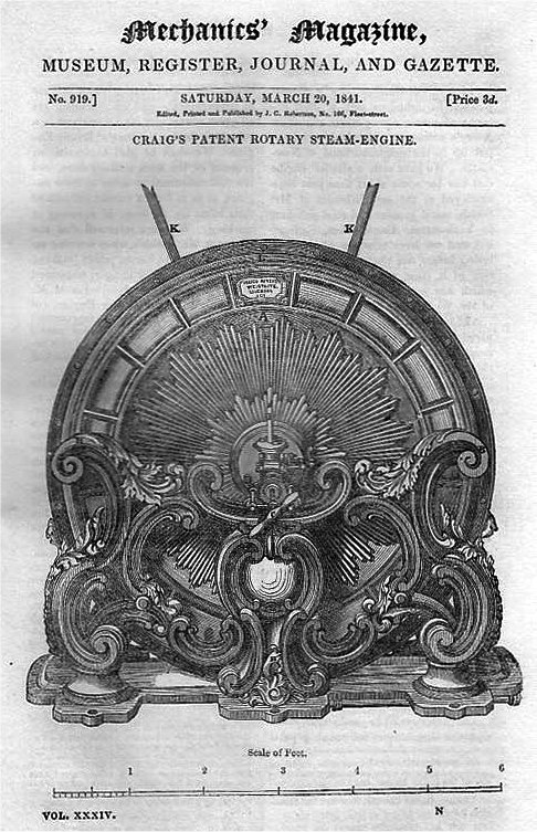 |
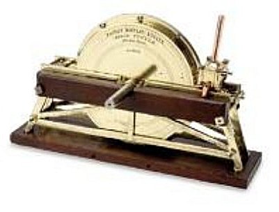
| Left: The Craig rotary engine: 1841
This picture appeared on the front of Mechanics Magazine. It was disappointing (after admiring the highly ornate exterior) to find that Craig's engine was only a crude turbine on the same principle as Hero's aeliopile. It is like a lawn sprinkler, with holes on opposite sides of the arms of the rotor. The engine was claimed to give 20 HP, but I don't believe it.
The slightly wonky scale at the bottom indicates that the engine was some six feet across.
You will note it is described as 'Craig's Patent Rotary Steam Engine'. The patent was sealed on 25th November 1834, seven years before the article appeared; the patent number has not yet been established.
The article is stated to be based on a pamphlet by Mr W Edwards Staite; there are some biographical details for him here, and in Wikipedia; the latter (in German for some reason) states that he developed the engine "with the London engineer Kennard", with no mention of anyone called Craig. It also states that the performance of the engine was found to be inferior to that of conventional steam engines. No surprise there.
Kennard may be Thomas W Kennard, a son of Robert Kennard; Thomas is described as a civil engineer. There is some biographical data on Thomas W Kennard here, but no mention of a rotary steam engine. Who Craig was is currently mysterious.
From Mechanics Magazine for Saturday 20th March 1841.
|
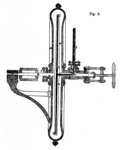 |
| Left: The Craig rotary engine: 1841
Section of the Craig engine showing the rotor arms inside the cylindrical casing. The power take-off pulley is at the left.
The text in Mechanics Magazine says that "It has been ascertained, (by a series of careful experiments) that the best speed of the arm to secure the greatest amount of useful effect or working power, is 45,000 feet a minute: that is the periphery of the arm should pass through space at 45,000 feet a minute." The best efficency will be given when the arm is moving at half the speed of the escaping steam.
That is interesting. We will assume the rotor is 5 feet in diameter, and that implies a rotational speed of 2865 rpm, which is pretty quick for 1841. The engine would need to be geared down considerably to do any useful work with the machinery of that time. There is no mention of this in the text.
|
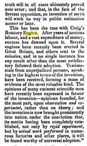 |
| Left: The Craig rotary engine: 1841
This part of the text from Mechanics Magazine makes some very ambitious claims, notably "Several engines have recently been erected in Great Britain, and others sent to the colonies..." Unfortunately this is in doubt because Google knows nothing that suggests anything of the sort.
|
Also from the text from Mechanics Magazine:
"A curious discovery has recently been made by the writer of this paper, in relation to the agency of electricity, which is not unlikely to lead to important results in practical science. The high-pressure steam used by the engine, is found to be highly charges with electric fluid. As the steam escapes through the nozzles it throws off brilliant coruscations of light, illuminating any substances placed within its influence..." The writer recognises that the electricity is produced by friction, but there is then some implausible speculation as to whether the electricity increased the effective pressure of the steam. "The first experiment satisfactorily proved the presence of electricity to an extent far greater than was anticipated. Indeed, the steam seemed to be so highly charged with it, that in the dark the entire volume of vapour (itself a bad conductor of light) was luminous, emitting sparks andstreams of brilliant electricity, which seemed to increase in intensity as the experiment was protracted."
Now you can see where this is heading; it is clearly a turbine version of Armstrong's electrostatic boiler. The basic phenomenon is usually said to have been discovered by engine driver Patterson in September 1840, near Newcastle. Staite is aware of this, but claims he made his electrical experiments "some weeks earlier". However, according to Wikipedia, the effect was first noticed by Alessandro Volta who dropped a red-hot cinder into water contained in a metal pan, and recorded that an electrity was generated. The experiment was replicated and described by John Read (of Knightsbridge) in his book A Summary View of the spontaneous electricity of the earth and atmosphere, etc, (Published 1793) the electricity produced being detected by an electrometer.
THE TUTTLE ENGINE: 1841
 |
| Left: Patent model of the Tuttle rotary engine: 1841
This engine was patented by Jesse Tuttle of Boston, Massachusetts. It had a toroidal cylinder in which a roughly cylindrical piston went round. On each side was one of the familiar 'sliding abutments' in the shape of two flat plates that slid in and out of the toroidal space with precision timing to allow the piston to pass. This idea repeats endlessly in the history of rotary steam engines; it would require fantastic speed and precision to avoid the leakage of steam, and I am not aware that anyone ever got it to work properly.
Model for US patent 2,015 of 1841
|
 |
| Left: The Tuttle rotary engine: 1841
The two 'sliding abutments' can be seen at each side of the circular casing. They are moved in and out by connecting rods joined to pins moving in slots in the casing; these pins are moved by cam grooves in an internal rotating plate.
The patent drawings show minor differences from the model.
From US patent 2,015 of 1841
|
 |
| Left: The Tuttle rotary engine: 1841
Fig 2 shows the cam grooves in the internal rotating plate that moved the two 'sliding abutments' in and out, and the piston mounted on a kind of stalk. Appropriate shaping of the cam grooves would allow the sliding abutments to pursue any sort of motion desired; that does not mean it could be made accurate enough for effective sealing of the steam chambers.
From US patent 2,015 of 1841
|
THE WALTER ENGINE: 1842
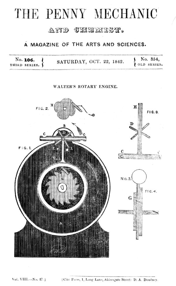 |
| Left: The Walter rotary engine
This engine is notable because a description of it given by the inventor himself exists. It is however, unfortunately the case that his description and drawings leave us little the wiser as to how it works.
From The Penny Mechanic Saturday 22 Oct 1842
Presumably a competitor to the better-knownMechanics Magazine?
|
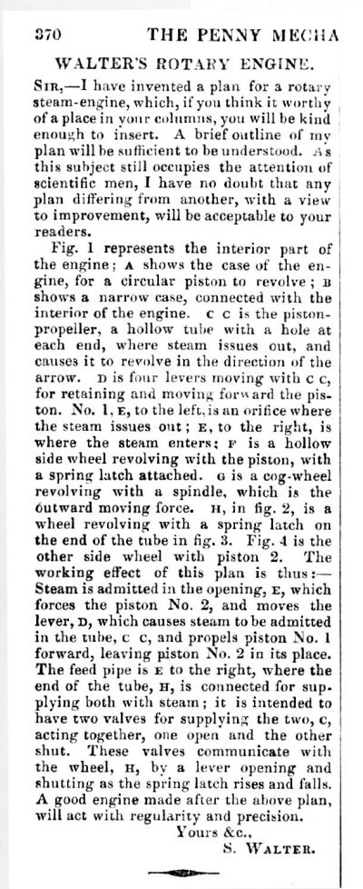 |
| Left: Mr S Walter attempts to describe his rotary engine
We start off with a very crude little turbine CC pinwheeling around on top of the main casing. This apparently stops and starts piston 1 in some way. Piston 2 can be seen in Fig 4, but where it fits into the main drawing is not shown. It appears that it changes place with Piston 1 as they go round, so it appears to be an engine of the pursuing-piston type, but quite how that is accomplished is a mystery.
Having spent some time trying to understand Mr Walter's description, I have decided there are better things to do; good luck with it.
One cannot help wondering what happened to Figures 2,3,5,6,7,and 8. Would they make things clearer?
From The Penny Mechanic Saturday 22 Oct 1842
|
THE LAMB ENGINES: 1842

|
| Left: The Lamb Rotary Engine: 1842.
This engine was patented in 1842; it was intended to work with air or gas as well as steam, or alternatively as a pump. Whether it was ever built or put to work is currently unknown.
"An annular cylinder with a fixed partition between the inlet and outlet. The piston is a hollow cylinder with a longitudinal slot, which slides up and down the partition, the outside of the cylinder wiping the inner surface of the shell. The centre of the traversing cylinder is pivoted to a crank pin, which carries it around a common centre shaft."
The piston b does not rotate, but rocks back and forth on its crank-pin as the gap in it moves up and down the fixed central barrier.
From "Mechanical Movements, Devices and Appliances" Hiscox, 1899
|
Note the similarity to the Trotter engine on Page 1 of this gallery.

|
| Left: The Lamb Rotary Engine animated
This gives a good idea of the sealing difficulties where the vertical partition goes through the chamfered gap in the rotating "piston". The combination of rocking, sliding, and a line contact make it virtually impossible to seal.
Animation kindly provided by Benoit Durand
|
Reuleaux says:
"(A line contact)…is used at 3, which almost destroys the possibility of that joint being steam-tight. The inventor rectifies this by the use of some additional closing piece, the nature of which he does not make clear, and which we have therefore omitted. (from the diagram) The tightness of this joint is not, however, important if only leakage could be prevented between the circular walls of the chamber and the piston where they are in contact, for Lamb uses the steam both within and without the annular piston.
In the position shown there is on the left between the piston and the outer wall of the chamber a considerable space, while between the inner side of the piston and the inner wall of the chamber an opening into which steam is admitted is just beginning to show itself. The action here begins when the outer space is just half full and the crank at the top of its stroke. The steam within the two complementary spaces within and beyond b is allowed to escape freely. As the crank rotates the slot at 3' moves up and down the fixed diaphragm in d, exactly as the pin 3 and block c in the last example. If no expansion were required only such valve-gear would be wanted as would suffice to prevent escape of steam in the lowest position of the coupler, where (as in Pattison's machine) the piston itself does not hinder communication between the two ports."
The last sentence in the commentary above reveals a hitherto unsuspected problem that afflicts some rotary steam engines. When the Lamb engine piston is at the bottom of the cylinder, a direct connection is opened between the steam supply and the exhaust, which briefly allows a large escape of steam. This would hardly be conducive to economy. Note that Reuleaux suggests that extra valvegear to prevent this could be added- but the potential simplicity of a rotary engine is once again compromised.

|
| Left: Lamb Compound Rotary Engine: 1842.
Reuleaux says: "(This diagram) represents a second of Lamb's machines, in which two similar mechanisms are united, one being placed within the other. The pistons b1 and b2 act quite independently- they are two couplers of unequal length driving a common crank... Mr Lamb insists most strongly that even more than two of the annular chambers and their ring-shaped pistons should be used together, intending that the second and following chambers should serve for the expansion of the steam. As the available chamber capacity both inside and outside the piston is filled and emptied once in each revolution, the machine may be considered double-acting." (p349)
From "The Kinematics of Machinery", Reuleaux 1876.
A triple-expansion rotary engine would certainly be intriguing (and probably unique) but I have found no evidence that one was ever constructed.
The algebraic stuff at the bottom is a sample of Reuleaux's notation for describing the kinematics of machinery. I have found no evidence so far that anyone found it useful.
|
THE HYATT ENGINE: 184?
I have at last found the source material on this engine, so here is some more information. Now read on...
This machine was called the "elliptic rotary engine" and was invented by Mr William Hyatt, engineer to the Champion vinegar works of Old Street, London, and was developed in conjunction with Mr Wright, the managing proprietor of the works. Burn says that the engine "does work in the most satisfactory manner" and was in daily operation at the vinegar works. Such statements are commonplace in the world of rotary engines, but the Hyatt engine, like many others, was never heard of again.
 |
| Left: Side view of the Hyatt engine.
a Cylinder
b Baseplate
l Shaft stuffing boxes
m Flywheel
n Support bearing
p Lubricator
q Lubricator control valve
| | | | | | | | | | | | | |
|
The cylinder was bored to an elliptical shape internally- which must have been an interesting task, given the technology of the period- and the shaft was "set eccentrically with respect to the minor axis of the ellipse" so that the revolving piston would fit accuraetely to the inner surface of the cylinder. This sounds geometrically a bit dubious, as an eccentric circle is not an ellipse, so I had better stick to quoting Mr Burn. "This is a peculiar and unlooked-for characteristic of the elliptical figure. The true action is only to be secured when the amount of ellipticity is exceedingly slight, the centre of motion of the revolving piston-shaft being in a line intersecting the minor axis, at about one-third of the length of such an axis."
Hmmm.
 |
| Left: Section through cylinder of the Hyatt engine.
The image here is not as clear as it might be, but there is clearly an eccentric assembly rotating inside the cylinder. There seem to be two slipper arrangements k that press on the cylinder walls, possibly pressed outwards by the item f, which may represent some sort of spring. The inlet and exhaust passages are at o.
Reuleaux is not impressed. He says: "The arrangement is of course quite worthless."
|
 |
| Left: Top view of the Hyatt engine.
Parts are lettered as in the drawing above.
|
The information on the Hyatt engine comes from "The Steam Engine- Its History & Mechanism" by Robert Scott Burn, published by Ward, Lock & Tyler. This book is unfortunately undated, but appears to have been in printed around the 1850's; it is certainly post-1844.See Bibliography at bottom of page.
THE BORRIE ENGINE: 1844
 |
| Left: The Borrie Rotary Engine: 1846
The Borrie engine was a version of the eccentric-rotor type of rotary steam engine. It does look a lot more workmanlike than some of the engines in this gallery; however it seems to have been no more successful.
The ports at the top were used for inlet and exhaust, being swopped over by the lever P at top left. The ports M and N were used for exhaust only. Here the engine is set to rotate anti-clockwise. The large curved pipe at the side led the exhaust steam to a jet condenser in the base of the machinery.
Note the details of the sealing on the sliding vanes, with anti-friction rollers pressed against them by springs. Opposing vanes are connected together by two rods passing either side of the central shaft. A packing box is placed at the top of the cylinder where the inner rotor supposedly makes a seal with it.
What about the end sealing? Mr Borrie says: "The rim of the inner cylinder is made to project into metallic packing boxes in the cylinder ends, whereby steam is entirely prevented from passing into the interior of the inner cylinder."
The designer was Peter Borrie, of 8 Princes Square, St George's East, London. There was a company of locomotive builders called Peter Borrie & Co, of Tay Foundry, Dundee, active around 1841. Gotta be the same chap.
Image from "The Engineer's And Mechanic's Encyclopedia", by Luke Hebert, 1846.
|
 |
| Left: The Borrie Rotary Engine: 1844
Here is another drawing, which reveals slightly different details. This one is probably derived from the patent drawing. Here is a naming of parts; note that "injection" refers to spraying water into the condenser to condense the exhaust steam.
B Outer casing
C Inner rotor
F Steam inlet
G Stop/start slide valve
H Stop/start control handle
J Steam chest
O Reversing slide valve
P Reversing control handle
Q Exhaust port
R Exhaust duct
S Condenser
T Injection slide valve
U Injection control handle
V Blow-through valve
Image and info from Mechanics Magazine Sat April 20, 1844, p257
|
 |
| Left: The Borrie Rotary Engine: 1844
Here is an external view of the engine, with just the condenser and air-pump sectioned.
D Rotor shaft
W Double-acting air pump
X Hotwell
c Pump drive eccentric
d Pump rocking shaft
h Boiler feed pump
j Feed pump valve chest
Mr Borrie produced a long theoretical analysis of his engine, in which he proved to his own satisfaction that his engine would require only a third as much fuel as a conventional reciprocating engine; we may assume he was in error, or we should have heard rather more about his engine.
The assumptions used in his calculations are however of interest as they presumably reflect the dimensions of the real engine- if indeed it was ever built. At the moment there is no evidence that it was.
The calculations assumed a casing diameter of 3ft 6in, and a length of 1ft 6in. The greatest distance between the rotor and casing was 7in. Steam pressure was 30 psi, and the rotational speed 50 rpm.
Image and info from Mechanics Magazine Sat April 20, 1844, p257
|
THE ELIJAH GALLOWAY ENGINE: 1846
 |
| Left: The Elijah Galloway engine: 1846.
This remarkable design was patented 14th December, 1846 by Elijah Galloway of Middlesex. Norbye writes that, like the Cooley engine, it is an important ancestor of the Wankel IC engine; however the principle of operation is quite different from Cooley and Wankel.
The inner rotor is a spider with five arms, each arm moving within one cell of the fixed outer casing G. The inner rotor is eccentrically mounted on a crank, and spring-loaded by a sort of circlip A so that the rotor extremities maintain contact with the inside of the housing, and the volumes of the chambers so created therefore increase and decrease as the crank turns. The large number of chambers in operation at different parts of their cycle should give a more constant torque than most rotary engines.
Steam enters through duct B, and leaves via the lower pipe.
Diagram from Norbye
|
 |
| Left: The Elijah Galloway engine: 1846.
Steam is admitted through circular ports in the cover plate seen on the upper left; each lobe had its own inlet and exhaust port. The exhaust ports can be seen branching out into a spur shape. There was some packing around the ports but no rotor seals. Steam leakage was high and efficiency correspondingly low.
According to Norbye, it was used as a marine engine, (which would appear problematical as there seems to be no means of reversing it) and developed 16 HP at 400-480 rpm. This does not tally with the Illustrated London News account below which implies that the output was more like 4 HP.
The lower diagram demonstrates the geometry of the five-armed rotor.
Galloway was a prolific inventor who also came up with the first feathering paddlewheel- patented in England in 1829, and also the Galloway non-dead-centre engine patented in 1838. See Polly Model Engineering (external link) This was an attempt to build an engine that could start in any position with a simple single crank.
He also wrote a book: "History and Progress of the Steam Engine", published in London in 1831.
Diagram from Norbye
|
 |
| Left: The Elijah Galloway engine animated.
The rotor has enough points of contact with the casing to constrain it to move in the circular fashion shown.
There looks to be a lot of unbalanced mass moving around here. Unless there was some scheme of balancing masses, I would have thought that the vibration at speed would have been severe.
This animation is kindly provided by Bill Todd
|
 |
| Left: The Elijah Galloway engine at work in Deptford: 1846.
According to The Illustrated London News for 20th Nov, 1847:
"It is used to drive the blowing machine at Mr Tyrrell's factory in Deptford, which that gentleman states requires about four horses' power" and goes on to say that the multiple chambers "...from the exquisite form and workmanship of cylinder and piston, are perfectly steam tight..." (ILN's italics) The diameter is given as 18 inches and the depth 8 inches. There is an unidentified feature under the output shaft which is probably a condensate drain valve.
Despite its alleged perfection, the Galloway engine did not prosper.
Picture and info from The Illustrated London News for 20th Nov, 1847.
|
 |
| Left: Animation of valve operation.
Showing how the cover plate moves over the top of the working spaces. Note how the curved sections of the ports in the cover plate move over the small circular holes in the main casing.
This topology, with narrow ports restricted in size by the thickness of the cover plate, does not look promising for obtaining a free flow of steam.
This stunning animation is kindly provided by Bill Todd
|
 |
| Left: How to Assemble Your Galloway engine.
This stunning animation is kindly provided by Bill Todd
|
PIERRET AND MOREL'S ROTARY STEAM ENGINE: 1847
 |
| Left: Pierret And Morel's Rotary Steam Engine: 1847
By Monsieurs Pierret And Morel of Paris.
It was rated at 4 horsepower. Steam comes in via the vertical pipe at the top. The hose leading down to the left carried away the exhaust steam.
From The Illustrated London News for 18 Dec 1847
|
 |
| Left: Pierret And Morel's Rotary Steam Engine: 1847
This shows the principle of operation. Steam enters via pipe A. The slide valve B, driven by an eccentric on the output shaft, admits steam alternately on the left and right side of the rotor, through the two hinged doors C and E.
The exhaust ports are at G and K.
No further reference to this engine has been found after the The Illustrated London News article, so it appears the design failed to thrive. Probably the impracticality of those doors banging about was the reason.
From The Illustrated London News for 18 Dec 1847
|
SIMPSON & SHIPTONS FIRST ENGINE: 1848
 |
| Left: The first Simpson & Shipton engine: 1848.
Here the cylinder swings back and forth as the piston rotates inside it.
It appears that a prototype at least was built, because Reuleaux says "A special test of it was made in 1848, which ostensibly proved that it really possessed the advantages claimed for it." However he goes on to say that it would be "extremely difficult to keep the piston steam-tight".
The mathematical stuff at the bottom describes the engine in Reuleaux's kinematic notation.
Diagram from "The Kinematics of Machinery" Franz Reuleaux
|
CAPTAIN FITZMAURICE'S ENGINE: 1849
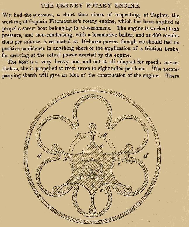 |
| Left: The Fitzmaurice engine: 1849
To the left is an account of the engine of a Captain Fitzmaurice. Not for the first time we read a highly enthusiastic account of a practical trial of a rotary engine, which was then never heard of again.
One cannot help noticing that the engine is very similiar to that of Elijah Galloway, just above. There are six chambers rather than five, but that seems to be the only difference.
It was not hard for the Museum staff to track down Captain Fitzmaurice: see William FitzMaurice. The Wikipedia entry does not mention any interest in rotary steam engines, but does make it clear where the Orkney name came from. Fitzmaurice’s elder brother was the fifth earl of Orkney.
From The Artizan 1849.
Thanks to Peter Short for bringing this engine to my attention
|
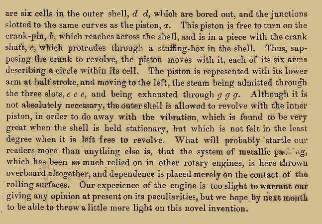 |
| Left: The Fitzmaurice engine: 1849
The rest of the article.
From The Artizan 1849.
|
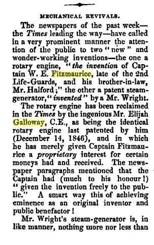
Some more information is given by this 1850 article from The Annual Of Scientific Discovery edited by David A. Wells and George Bliss. It appears to have been taken fron the London Times.
NEW ROTARY ENGINE
"Several trials have been made, as we learn from the London Times with a rotary engine, which has been brought to its present working
condition by Hon. W. E. Fitzmaurice. The engine is very simple, merely consisting of two pieces so mathematically arranged that the
interior part works in the outer with the greatest ease, being free from dead points and without the slightest vibration, however great the velocity. It has no springs or packing, and the parts meet each other so harmoniously as only to give a humming noise like a spinning top, and it is not in the least liable to get out of order, the wear being perfectly uniform throughout. The entire motion being a rolling instead of a cutting one, the engine will last long without repair, as the surface becomes case-hardened in a very short space of time.
The trial took place in the presence of several scientific gentlemen and engineers of eminence in their profession, in a frigate's
pinnace, the engine being constructed for the government. The boat is of 10 tons burden, carrying a load of 5 tons, and drawing 4 feet of water. She is 33 feet long and 8 feet breadth of beam, made for carrying men and carronades, but not in any way calculated for speed, and yet the engine of 10 horse-power, occupying a space of 21 inches by 7 inches, drove a screw-propeller of 3 feet in diameter and 4 feet pitch with such velocity as to make 300 revolutions in a minute, the motion being given on the direct-action principle.
Although the boat was not at all calculated for speed, she was propelled against the Stream a distance of 8 miles in 20 minutes, eqnal, allowing for the strength of the current, to 8 miles an hour. The engine weighs considerably less than 1 cwt. to each horse-power, and requires much less fuel than the ordinary engines, and is so easily set in motion, graduated to any velocity, or stopped, that a boy of 12 years of age might manage it with one hand. The best judges have pronounced a high opinion of its capabilities, after witnessing its performances. Captain Fitzmaurice makes no secret of the invention, but shows its interior freely, as it is intended for the public service. An engine of 100 horse-power on Captain Fitzmaurice's construction would only occupy a space of 4 feet by 2 feet."
 |
| 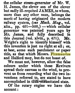 |
| Left: The plot thickens...
This article makes it very clear that the "Fitzmaurice engine" was indeed a copy of the Galloway engine, the only difference being that it had six chambers instead of five.
One feels for the clever but sadly ill-requited JAMES.
From The Mechanics' Magazine, Museum, Register, Journal, and Gazette Volume 15, p349, Sat 22 Sept 1849
|
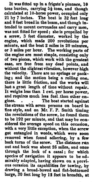 |
|  |
| Left: Another description of what was apparently a highly successful trial
...unfortunately followed by oblivion.
From The Mechanics' Magazine, Museum, Register, Journal, and Gazette Volume 15, p349, Sat 22 Sept 1849
|
 |
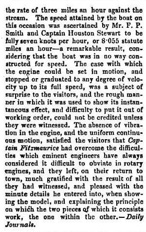
| 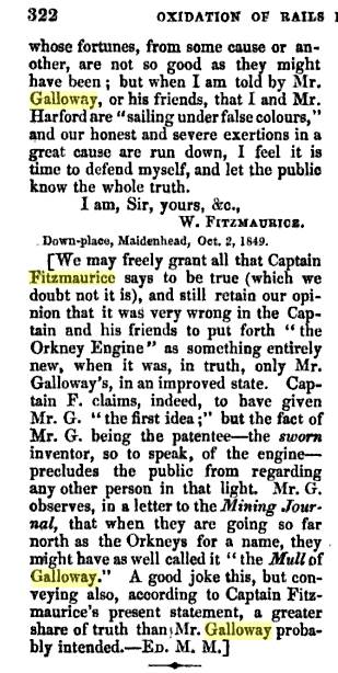 |
| Left: Captain Fitzmaurice fights back
It sounds as though Mr Galloway was not doing too well at this point.
From The Mechanics' Magazine, Museum, Register, Journal, and Gazette Volume 15, p349, Sat 13 Oct 1849
|
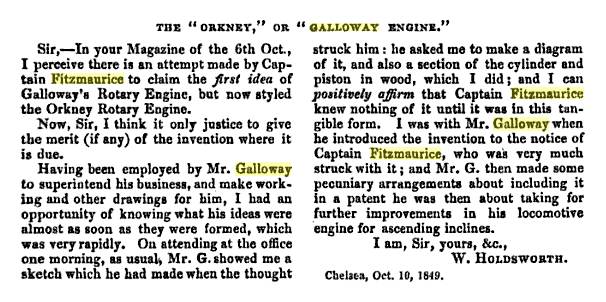 |
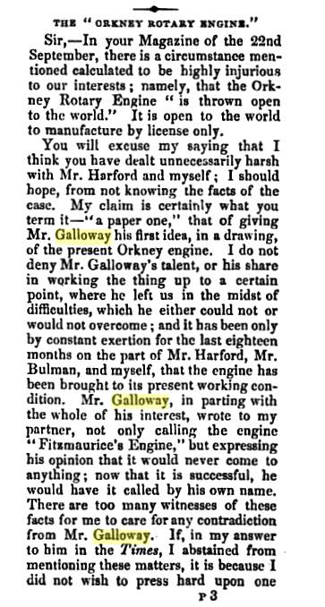
| Left: Mr Galloway's associate weighs in
Sounds convincing to me.
This is as far as the Fitzmaurice engine story has been traced to date. There may well be more information in the later pages of the Mechanics' Magazine.
From The Mechanics' Magazine, Museum, Register, Journal, and Gazette Volume 15, Oct 1849. (Sorry, exact date mislaid)
|