Gallery opened: Aug 2004
Updated: 24 Aug 2016
Photo of engine model


The Tower Spherical Engine. |
Gallery opened: Aug 2004 |
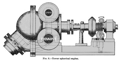
| Left: The Tower Spherical Engine.
Now this is a real beauty.
The operation of the engine is not easy to comprehend, but goes something like this: The "cylinder" is spherical, and contains two quarter-spheres, with a thin circular disc between them. The two quarter-spheres rotate and engage rather like a universal joint, creating four cavities in the sphere, two of which are expanding and two contracting at any moment. By suitably timing admission and exhaust, rotational power is generated.
The prototype was intended for the direct drive of dynamos, and had a speed range of 600 to 1100 rpm. A 10-inch engine (presumably this means one with an internal sphere diameter of 10 inches) was reported to consume 37 pounds of steam per BHP-hour. The worm on the right operates a small reciprocating pump for forced lubrication.
Inventor: Mr Beauchamp Tower
|
The introduction of the electric dynamo, which was best driven directly by a high-speed engine, gave a new lease of life to rotary steam engine development. If these engines could have been made to work efficiently, they would have been ideal for the purpose. Note that the Hult engine was said in 1902 to have been used for driving lighting generators in both the Russian and Swedish navies. This was clearly shown at the International Inventions Exhibition at South Kensington, London, in May 1885, where several engines were shown that were specially designed for driving dynamos directly. These included The Parsons Epicyclic Engine, and of rather greater import, the Parsons steam turbine. Ironically, the Parsons turbine was illustrated on the same page as the Tower engine.
In the event, most generators of the day were driven by Willans or other relatively conventional high-speed reciprocating engines.
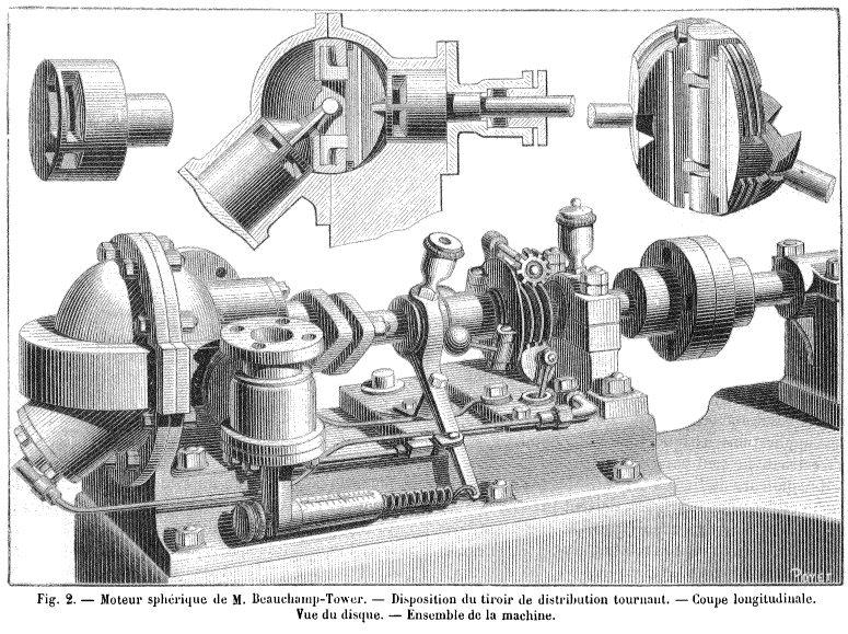 | |
Above: An engraving of the Tower engine, from the French science journal Nature: 1884. |
The Nature article adds little to the description of the engine, but does give some performance figures, thus:
"At 500 rpm, a Tower motor with a 10 cm sphere can produce one brake-horsepower with steam at 3 atmospheres (44 psi) and 2.5 brake-horsepower if the pressure reaches 8.5 atmospheres (125 psi). A 20 cm motor produces 7 brake-horsepower at 3 atmospheres, 10 brake-horsepower at 4 atmospheres, 15 brake-horsepower at 6.5 atmospheres and 20 brake-horsepower at 8.5 atmospheres. The biggest model, of 65 cm diameter, produces between 234 and 624 brake-horsepower, depending on the steam pressure. Unfortunately we have no figures on the steam consumption corresponding to these different pressures. It is to be feared that it is much greater than motors with conventional cylinders and pistons."
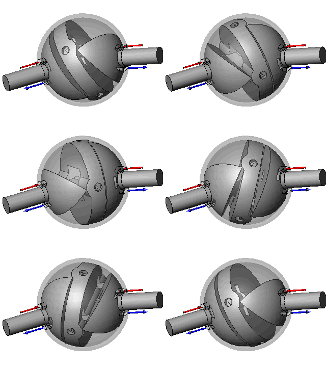 | Left: Animation of the Tower engine
|
There was no information on why the author thought the steam consumption would be greater with a rotary engine- but almost certainly it would be the old story of leakage due to packing problems and inadequate steam expansion due to the cramped geometries usually employed. He seemed to take it pretty much as a foregone conclusion, however, and in the case of the average rotary engine, there is no doubt he was justified.
The author concluded that the higher steam consumption was usually justified by the smoothness of rotation. However, potential customers seem not to have agreed, as the Tower engine has left little mark on history.
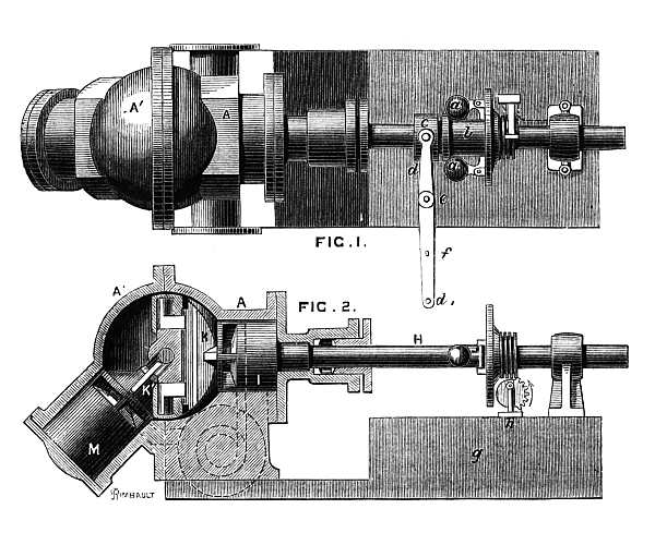 | Left: Illustrations of the Tower engine, from the Engineering report on the International Inventions Exhibition.
|
Below is the complete text of an article on the Tower engine that appeared the British journal Engineering. The date was March 27th, 1885.
 | Left: A contemporary article on the Tower engine.
|
 | Left: The article continued.
|
 | Left: The article continued.
|
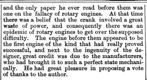 | Left: The article concluded.
|
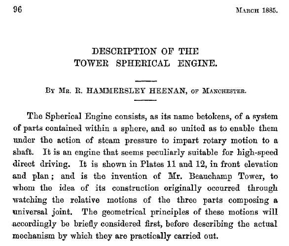 | Left: The start of a paper by R Hammersley Heenan on the Tower engine
Volume 36, March 1885 |
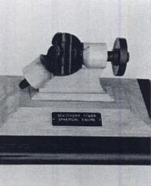 | Left: Model of The Tower engine
|
Students of the rotary steam engine galleries will have noted the close relationship between rotary engines and rotary pumps. The Tower engine appears to have resurfaced as a pump in the late 1950's, though what, if anything, happened in the intervening period is unknown.
To quote the source:
"When the rotor revolves, four sets of flat surfaces open and close for a pumping action of four discharges per revolution."
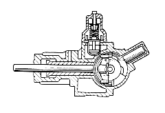 | Left: The Tower engine reborn: the universal-joint pump.
|
MR BEAUCHAMP TOWER (1845-1904)
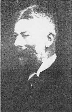 | Left: Mr Beauchamp Tower.
|
I was planning to open this page with a remark that the Tower Engine was nothing to do with Tower Bridge in London. Fortunately I didn't, as there does appear to be some sort of link.
Henry Marc Brunel (born 27 June 1842, London) was the second son of the famous Isambard Kingdom Brunel. Throughout 1886 Beauchamp Tower and Henry Brunel were involved in working on Tower Bridge. From 1880 Henry Brunel was a member of a company promoting Tower's Spherical Engine; another member of the syndicate was Sir Frederick Bramwell. Tower had to demonstrate that the spherical engine could run satisfactorily for three million revolutions before the syndicate would back it. This was achieved and it is said that a considerable number of the engines were then built, though the actual number has so far escaped detection.
One of the strangest things about Mr Tower was that his name echoes part of the Tower of London, which is of course very close to Tower Bridge. There is a "Beauchamp Tower" built around 1275-81, and named after Thomas Beauchamp, Earl of Warwick. I wrote here earlier "I can only assume that Mr Tower's parents had a rather peculiar sense of humour."
In fact the situation is a bit more complicated. His grandfather, Christopher Thomas Tower (1775-1867) married Harriet, daughter of Sir Thomas Beauchamp-Proctor in 1803, so this is where "Beauchamp" enters the Tower family. It still, however, seems a bit strange to take half of a double-barrelled surname and use it as a first name, and it is hard to see that the Tower of London reference is purely a coincidence.
Never let it be said that this site fails to bring you the important details.

  
|