Most steam locomotives have steam cylinders and pistons that move the driving wheels directly through connecting rods between the cross-head and crank-pin. A few designs used connecting rods to rotate a jackshaft or intermediate shaft, with no wheels on it, which was in turn coupled by rods or gearing to the driving wheels.
The jackshaft locomotives included here use both gearing and rod-coupling, and overlap somewhat with Geared locomotives; of which an example is the Climax type. More examples can be found on the Locomotive Index page.

GRASSHOPPER LOCOMOTIVES
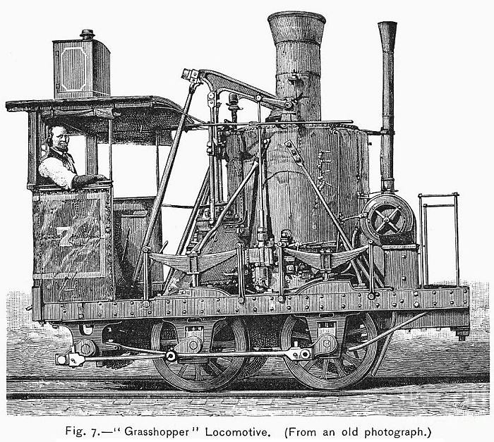 |
| Left: Grasshopper locomotive with jackshaft drive
Grasshopper locomotives had vertical cylinders and a roughly horizontal beam, which was thought to resemble the back leg of a grasshopper. The first of the type was the Atlantic, built by foundry owner and inventor Phineas Davis in 1832 for the Baltimore and Ohio Railroad. (B&O) It was in fact the first commercially successful and practical locomotive constructed in the USA.
It is not clear if this image shows the Atlantic, but it is certainly a grasshopper type with geared drive to a jackshaft. It therefore also qualifies as a lever-drive locomotive and also a geared locomotive.
It is possible that it is actually the "Andrew Jackson" built in 1836 by Ross Winans and George Gillingham. The Andrew Jackson operated until 1892 when it was altered to resemble the original Atlantic (No. 2) for an exhibition at the World's Columbian Exposition in Chicago, in 1893. The original Atlantic had been scrapped in 1835 for unknown reasons, despite its operational success. The Andrew Jackson has been known as the Atlantic ever since the Exposition. The cab and connecting rods were removed to represent the Atlantic of 1832 and it was renumbered as the "No.2" in January of 1884.
Against this is the fact that the original Atlantic had its crankshaft geared directly to the rear axle, and did not have a jackshaft. If anyone can definitely identify the picture I would be very grateful.
The Atlantic grasshopper locomotive has a Wikipedia page.
|
 |
| Left: The Atlantic in the 1920's
The original photograph had some old cars in the background which put the date somewhere in the 1920's, so this is clearly the replica Atlantic, as shown on the Wikipedia page.
Note that there is no jackshaft- the crankshaft is geared directly to the axle.
|
THE BOSTON-OHIO CRAB LOCOMOTIVES
The "crab" locomotives were an early vertical-boiler design that appeared on the Baltimore-Ohio railroad in 1837. The type was developed by Ross Winans, the format apparently being inspired by Tom Thumb, built by Peter Cooper in 1830. The crabs had driving wheels 36" in diameter, and the cylinders were 12.5" by 24"; the weight was only 12 tons. They were known as "crabs" because to onlookers used to more conventional designs, they appeared to be going backwards. It appears only two of this type were bought. It was said they had the reputation of "pulling like elephants," but reliability was poor.
The short wheel base was due to the large number of sharp curves on the first section of the Baltimore and Ohio railroad; at first it was seriously questioned as whether locomotives could ever be successfully substituted for horses on the line. The crabs were designed to burn anthracite, when most US locomotives of the time burned wood. Winans was granted US Patent No 308 for the design, on 29 July 1837.
 |
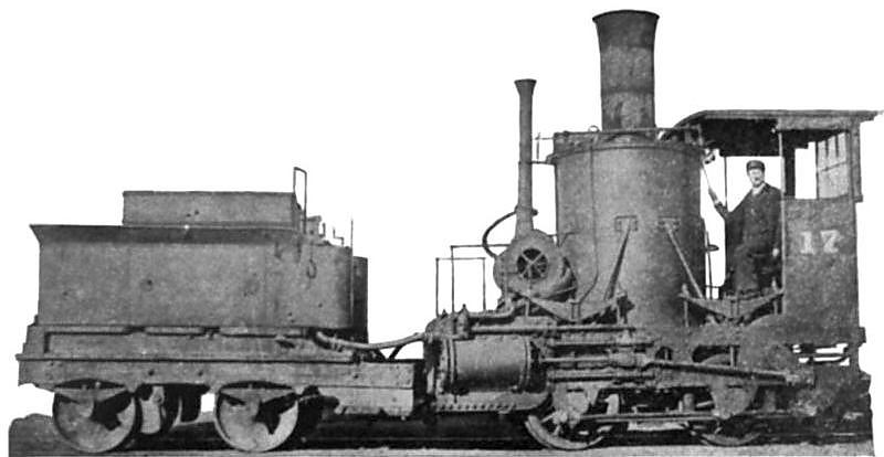
| Left: 0-4-0 Crab locomotive "Mazeppa": 1837
Here the jackshaft is at the extreme left, driven by step-up gearing with a ratio of about 1:2 from the crankshaft above it. The jackshaft is coupled to the two driving axles.
One of the peculiar features was the absence of a blast-pipe; the exhaust from the cylinders escaped via the Y-shaped pipe next to the boiler. The firedoor was accessed through the two arms of the Y. Draught was provided by a fan mounted under the footplate and blowing into the ashpan; according to the patent this was "propelled by the exhaust steam from the cylinders" using a "steam wheel" which was a crude sort of steam turbine. I suspect this may have been one of the less satisfactory aspects of the design.
The Mazeppa was the first of the crab locomotives. The name appears to come from Byron's epic poem Mazeppa, which describes an unfortunate incident involving a wild horse.
Mazeppa was also the name of a locomotive on the Shropshire Union Railway in Britain, which in 1852 left its shed by itself as it was getting steam up, and collided with a passenger train, killing one of the passengers; see LTC Rolt's wonderful book "Red For Danger".
Engraving dated 1844
|
 |
|
Above: 0-4-0 Crab locomotive "Mazeppa"
Mazeppa is shown here after many year's service, but the date of the photograph is currently unknown. A cab has been added, making it a cabforward design. Here struts have been added to the boiler, and a replacement fan appears to have been fitted.
The Mazeppa was on display at the Field museum in Chicago around 1905, but appears to have later been disposed of.
|
WINAN'S 'MUD DIGGER' LOCOMOTIVE
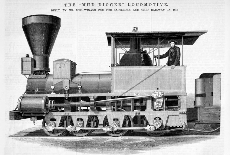 |
| Left: Winan's 'Mud Digger' Locomotive: built 1844
This is clearly a jackshaft locomotive, but information about it is very scarce. No. 37 was one of the so-called "mud diggers" built by Ross Winans in the 1840's. No 37 weighed 23.5 tons.
Why the "mud digger" name was attached to this design in unknown and quite frankly Google has been no help. It is also unknown why jackshaft drive was adopted; looking at the spacing of the axles and jackshaft it seems likely that some reduction gearing was used between crankshaft and wheels, but of no great ratio. (1:2 or less?)
I do hope some of you out there have more information; it is greatly needed.
|
JACKSHAFT CRAMPTONS ON THE SOUTH EASTERN RAILWAY
 |
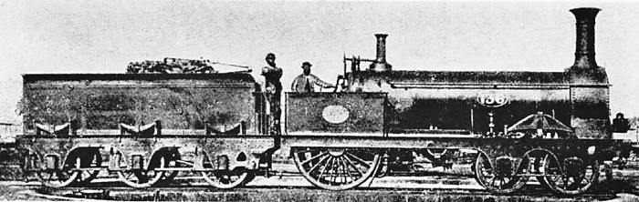
| Left: No 136 "Folkstone": built 1851
This jackshaft locomotive was built for the South Eastern Railway in 1851. It is a Crampton type, ie the single pair of driving wheels was placed right at the back, with the axle running behind the firebox. This gave a low centre of gravity without the complications of running axles through the boiler. (this was tried by somebody!) This in itself was not unusual for the time, the Crampton layout being popular until its inherent defect- lack of adhesion weight on the driving wheels- could no longer be overlooked. The idea was introduced by Thomas Crampton.
This photograph shows "Folkstone" on display at the Great Exhibition of 1851.
|
The idea behind the "Folkstone" class (Nos. 134 to 143, all built in 1851) was to combine inside cylinders (placed under the boiler) with the Crampton layout. Since a cranked driving axle could not be used (the connecting rods would have to pass through the firebox) the drive had to be split by passing it down each side of the locomotive. The jack-shaft was cranked and was driven by the inside cylinders, and then two coupling rods passed the drive to the wheels.
The intended name was Folkestone, a port on the Kent coast, but this was spelled "Folkstone" on the nameplate, as can be seen in the photograph. This sort of thing was not uncommon when foundry workers were not that educated; L T C Rolt gives an example of "Goliath" being rendered as "Goliah". This appears to be the only locomotive of the series that was named, probably because it was chosen for display at the Great Exhibition of 1851. "Folkstone" was built by Robert Stephenson & Company.
These locomotives must have been reasonably successful as they stayed in this form until 1869, when most of them were rebuilt in the 2-4-0 configuration, with the rear axle still behind the firebox. This was no doubt to get more of the boiler weight onto the driving wheels.
 |
| Left: No 136 "Folkstone" on a turntable
Here the coupling-rod between jackshaft and driving wheel is hidden as it is tucked up under the frame.
Date of photograph unknown.
|
A further series of jackshaft Cramptons called the "Coquette" class were built in 1862 for the London, Chatham And Dover railway in Kent. They were all named after skittish sorts of female, the other four being Echo, Flirt, Flora, and Sylph. Someone wasn't taking the naming business too seriously.
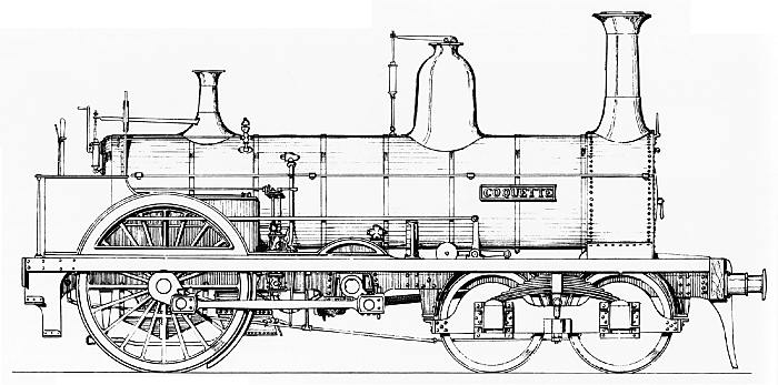 |
| Left: Coquette: built 1862
The main difference from the Folkstone design was the use of a front four-wheeled bogie with a central pivot. This meant no castoring action to guide the bogie, and there were no locating springs; this appears to have caused trouble.
The lack of adhesion soon made itself felt and they were rebuilt as conventional 4-4-0s in 1865 and 1866.
The driving wheels were 6ft 6.5in in diameter.
|
JACKSHAFT LOCOMOTIVES IN INDIA
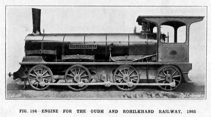 |
| Left: No 4 PERLEEWERLEE: 1865
Two batches of 0-8-0 jackshaft engines were built by Sharp Stewart for the Oudh and Rolikhand Railway.
The first four were built in 1865 and numbered 1-4 Class A (SS 1641-1644)
All were four Named: No 1 JIMPEEBUTTEE, No 2 BOTEETUTEE, No 3 DAOTHABTEE and No 4 PERLEEWERLEE.
The nameplate here is just readable as PERLEEWERLEE.
Another two were built in 1868 and numbered 5 and 6 Class A. (SS 1875-1876)
|
The locomotive was built for the Indian Broad Gauge of 5 ft 6 ins, which is the broadest gauge in use in the world today.
Dimensions: Both batches -
CW 48", Cyls 161/2"X24", EHS 1108, GA 161/2", AL 81/2", EW 33 and TW 28.
Photo source: The Engineer.
Reference: (1990) INDIAN LOCOMOTIVES Part 1 - BROAD GAUGE 1851-1940 Hugh Hughes CRC UK p 86 Roster, p 89 Notes and p 107 Dimensions ISBN 0 9503469 8 5
THE JOE BELL LOCOMOTIVE
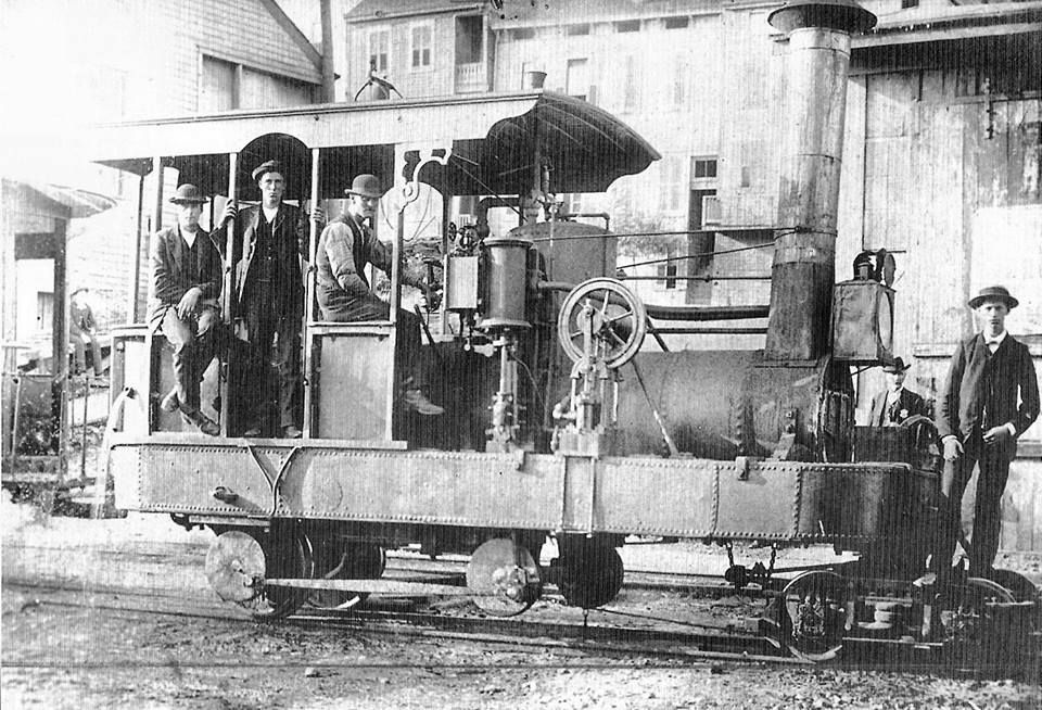 |
| Left: Joe Bell locomotive: built 1873
This image is about on the Internet but I have unable to find any info at all apart from its name 'Joe Bell' and the date of construction. I have seen it referred to as a 'geared locomotive' but it looks to me as if the horizontal coupling rod drives the rear axle directly.
The thing with the flywheel is presumably the boiler feed pump. Note water pouring from the tank on the far left.
|
THE HONEGGER RACK LOCOMOTIVE
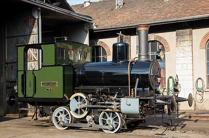 |
| Left: Honegger rack locomotive: built 1877
This rack locomotive "Caspar Honegger" was built in 1877 by the Maschinenfabrik Aarau for the Honegger power loom factory at Ruti, which had a rack track connecting to the local station. The locomotive weighs 15 tons and produces about 125 HP. It was working at the Ruti factory until 1951. It is shown here in magnificent condition after 16 years of restoration work by the owner.
The Ruti loom business was founded by Caspar Honegger (German Wikipedia) It was a major employer until the 1980's.
|
The drive arrangements are unknown but presumably the jackshaft is geared to the middle axle, which has a rack-wheel of the same diameter as the outside wheels. This axle then drives the front and rear axles through coupling rods; provision for some vertical movement can be seen. Note also the brake band around the jackshaft wheel. It carried works number 11 when built.
FOWLER JACKSHAFT LOCOMOTIVES
 |
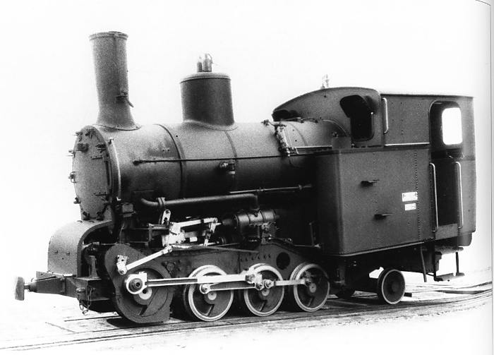
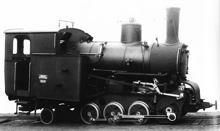
| Left: Fowler jackshaft locomotive: 1880
The first locomotives built by John Fowler for light railway systems had small wheels and as a result apparently suffered from their working parts being too near to the ground, and so exposed to dust and dirt. In July 1880, his employees Alfred Greig and William Beadon were granted a patent for a locomotive with jackshaft drive, which meant the cylinders could be raised much further above the track. Note the very short coupling rod from the jackshaft to the rear axle just below it; the rod is cranked to allow the valve eccentrics to be mounted inboard of the crank.
|
AIX-LES-BAINS RACK LOCOMOTIVE
 |
| Left: Aix-Les-Bains loco S1: built 1929
A single-track metre-gauge rack railway ran from Aix-Les-Bains up to Mount Le Revard in Savoy, France. It worked on the Abt rack system. The severe gradients required sloping locomotive construction to keep the water level in the boiler. The line was originally worked by seven 0-4-2 lever locomotives, but in 1929 a single more powerful 0-6-2 design was purchased, so that two carriages rather than one could be pushed up the gradients.
The cylinders drove a crankshaft at the front of the engine, which was then geared down (by about 1:2, looking at the photograph) to drive a jackshaft below it. This then drove the three powered axles via a neat triangular structure. The small crank visible drove the valvegear; the connecting rod between piston rod and crankshaft is presumably behind the gear casing. A superheater was fitted.
Manufacturer's photograph
|
Note the water gauge positioned not in the cab but some way along the boiler, between the steam dome and the cab front. This gave more accurate readings on changing gradients. Its vital test cocks appear to be worked by a rod from the cab.
 |
| Left: Aix-Les-Bains loco S1: built 1929
The other side of the locomotive; note there is a water gauge on this side too. The white object under the curved front cover is probably part of the crankshaft.
Working pressure: 203 psi
Weight empty: 18,155 kg
Working weight: 22,275 kg
Cylinder diameter: 300 mm
Piston stroke: 400 mm
Manufacturer's photograph
|
The builder "SLM" was the Swiss Locomotive and Machine Works (in German: Schweizerische Lokomotiv und Maschinenfabrik) at Winterthur, who were the go-to guys for mountain railway locomotives.
The railway was closed in 1937, being replaced by an aerial cableway. One of its lever-drive locomotives (No 8) has been preserved, but apparently not this fine machine. Shame.
HORNSBY-AKROYD JACKSHAFT LOCOMOTIVE
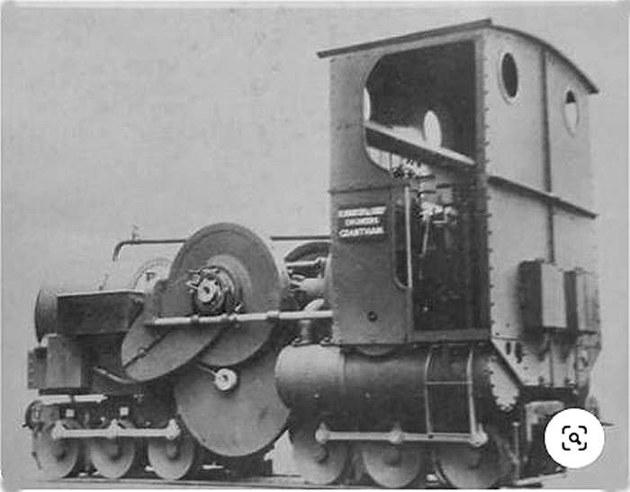 |
| Left: Hornsby-Akroyd jackshaft engine: 1903
This picture was Found on the Web, and an image search revealed it was a Hornsby-Akroyd internal combustion engine locomotive of the 2ft 6in gauge Chattenden & Upnor Railway. (Works No. 6234). The drive system consists of two 0-6-0 coupled bogies, (possibly only the 0-6-0 on the left is actually a swivelling bogie) presumably driven by gearing from the lower central wheel; I assume this gearing was arranged to allow for the swivelling of the bogie, as in the Luttermoller system. The lower central wheel is driven from the upper shaft, which carries a flywheel on each end.
The upper shaft also carries a chain-case (to drive the valve gear?) and it looks as though there may be a helical drive to the horizontal shaft that runs into the cab. The single-cylinder horizontal 20 hp compression-ignition (semi-diesel) engine had two opposed pistons. A two-speed transmission was fitted.
|
This the first known C-C-C locomotive design recorded. It seems like rather an advanced design, with certainly no mistake about using all the adhesive weight. However, it is reported as being underpowered, with an inefficient transmission, noisy, and difficult to start. In fact, how did you start it? Was there a tank of compressed air on board? Disposal unknown.
For Russian jackshaft-drive locomotives, see No 8000 and No 8001 in the Russian Reforms gallery.
The Swiss Eb3/5 high-pressure locomotive had jackshaft drive; see The Swiss High Pressure Locomotive
Several of the steam turbine locomotives had jackshaft drive; see The Swiss Zoelly Turbine, The Armstrong-Whitworth (UK), the The Swedish TGOJ Turbines and The German Turbines
Conventional piston steam locomotives with jackshafts were relatively rare, but the technique was used more extensively on early electric and diesel locomotives.
|
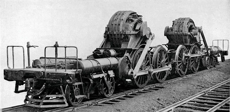
Above: A serious bit of jackshafting to connect big electric motors with two-coupled axles: 1910
These are the internals of a Pennsylvania Railroad's class DD1, introduced in 1910; they were semi-permanently coupled pairs of third-rail DC electric locomotives. One pair has been preserved at the Railroad Museum of Pennsylvania; see Wikipedia for more details of this remarkable bit of machinery. Despite the clumsy-looking drive system, they were said run quietly and smoothly.
|
|
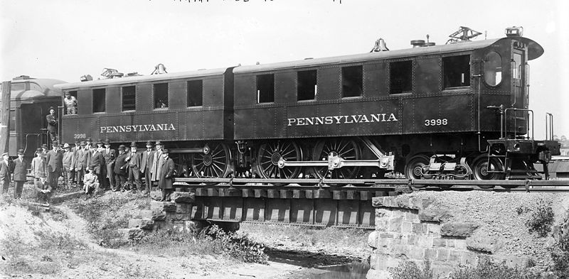
Above: A Pennsylvania Railroad class DD1: 1910
No 3998 with its clothes on. Note that both halves carry the same number.
|
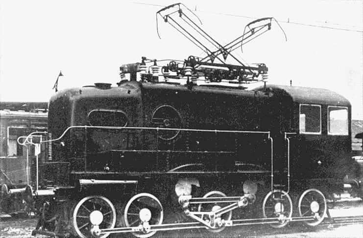 |
| Left: Some more serious jackshafting
This jackshaft system appears to couple two electric motors to four driving axles.
The small, single cab electric locomotive was an experimental design by the Hungarian engineer Kalman Kando for the Hungarian Ministry of Transport in the early 1920's. The design incorporated Kando's invention the 'Kando Triangle' in the jackshaft drive; this was a tilting element of the rod drive that allowed the driving wheels vertical movement without putting vertical forces on the connecting rods. Kando worked for the important Hungarian manufacturer Ganz.
|
Much more information can be found here and here.
Thanks to Stephen Holland, Ralph Brades, and Dr Lawrence E. Hawkins for identifying the locomotive and providing additional information.
The Kando drive was also used on the Paris Orleans Railways, on the P.O. E401 locomotive "La Hongroise" which was built by Ganz in Budapest. There is a good picture of a model here. Two appear to have been built; they proved unsuitable for the high speeds intended, and were taken out of service in the 1930's; however during World War II they were put back into service and operated until 1942, when they were scrapped.


