Gallery opened: 1 Mar 2014
Updated 30 Oct 2025:
Yet more on the Belpaire Lever Locomotive here.


Lever-Drive Locomotives |
Gallery opened: 1 Mar 2014
|
|
CONTENTS OF THIS PAGE
Googling "lever drive locomotive" brings up little that is relevant, apart from this website. This must be a more obscure subject than I thought. Hopefully this modest page will change that.
![]()
THE CARMICHAEL LOCOMOTIVE: 1833
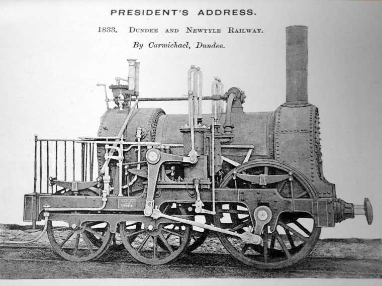 | Left: Carmichael 0-2-4: 1833
|
![]()
THE LABLACHE LOCOMOTIVE: 1848
This locomotive made use of a rocking-shaft drive system.
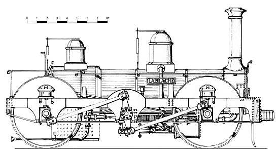 | Left: The "Lablache" 0-4-0 with rocking shaft
|
The name was originally of puzzling origin. I decided it was probably it was named after Luigi Lablache, (1794-1858) a famous Italian opera singer, most noted for his comic performances. This now seems confirmed by a Scientific American article called 'Some Locomotive Curiosities' by Herbert T. Walker, issue for 16 December 1911.
Here is what Herbert Walker had to say about the "Lablache":
"It was designed by the celebrated Crampton in 1847 and patented by him. The driving wheels were 6 feet in diameter. Cylinders 16 inches in diameter by 20 inches stroke. Weight 3?? tons. [sic] Total heating surface 1,271 square feet. This engine was named �Lablache,� after a noted operatic singer of the day. Details of its performance cannot be given here, but we may note that the engine was officially timed at 79 miles an hour with a light train. On one occasion the �Lablache� hauled a freight train of 430 long tons at an average speed of 30 miles an hour, which was no mean performance at that period.The peculiarity of this engine was that the cylinders inside the frames actuated vibrating arms connected to the outside levers called the �side levers.� These side levers were coupled to the cranks in such a way that when the front driving wheel crank was, for example, on the back center the rear crank was on the front center, and thus the stresses of these oppositely moving parts were balanced. Moreover, the cylinders, guides and vibrating beam fulcrums were all bolted rigidly to the frame and therefore not subject to the effects of cross-head vertical thrust, as in the ordinary locomotive. The �Lablache� was tried on the Midland and other railways in England, but no company would purchase it on account of its great weight, and it was in use only a short time." |
This tells us that the cranks on each side were set at 180 degrees apart, to obtain the sought-after balance, rather than at 90 degrees as usual. One wonders if there were dead-centre problems.
The rocking shaft should not be confused with the use of a rotating jackshaft to drive the main wheels. A number of such designs were built in the early days of English railways, such as the "Folkestone" class of Cramptons (Nos. 134 to 143) built for the South Eastern Railway from 1851 onwards.
![]()
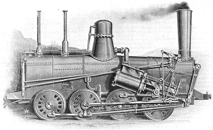
BELPAIRE'S LEVER-DRIVEN DESIGN: 1873
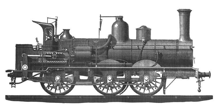 | Left: The Left: Lever-driven locomotive No 761, designed by Belpaire and Stevart: 1873
|
TECHNICAL DATA. |
Cylinders 450 x 600 mm
Wheel diam 1.70 m
Safety valves Ramsbottom
ExhaustBoty variable
Injectors Friedmann |
Note the Boty variable exhaust in the technical data; this was presumably a variable-aperture nozzle to optimise the draught. The name is unknown to Google. (Still true in December 2019)
No 761 was retired in 1901. Since it gave more than 25 years service, it can't have been too bad a design. It is however an unresolved question as to whether it kept its lever-driven system for all its life. It is unknown to Google, apart from on this site.
 | Left: Article on the valve-gear of the Lever locomotive: built 1873
|
 | Left: Diagram of the valve-gear of the Belpaire locomotive: 1873
|
This locomotive can also be seen in the Strange Doings In Belgium gallery.
![]()
THE SYSTEME BROWN
The "Systeme Brown" had a central rocking lever which allowed a reasonable length of connecting rod to be fitted into a short wheelbase, and Brown valvegear. Connecting rods cannot be made too short because this increases the angles at which they operate, and leads to excessive side forces in the crossheads, and increased friction and wear. If a central lever is used as shown below, the cylinders can be tucked above the front wheels, reducing the overall length of the engine; this was an advantage on tramways and mountain railways built with sharp curves. Another advantage is the very short pipe runs to the cylinder and back from it to the blast-pipe. The system was introduced by an Englishman, Charles Brown, of whom more below. A full description of the Brown gear was published in the Proceedings of The Institution of Mechanical Engineers for January 1880.
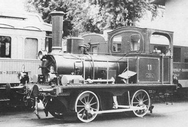 | Left: Lever locomotive 0-4-0 No 11: built 1881
Builder: SLM Operating weight: 14.68 tonnes Length between buffers: 6.60 metres Maximum speed: 50 km/hour Gauge: standard |
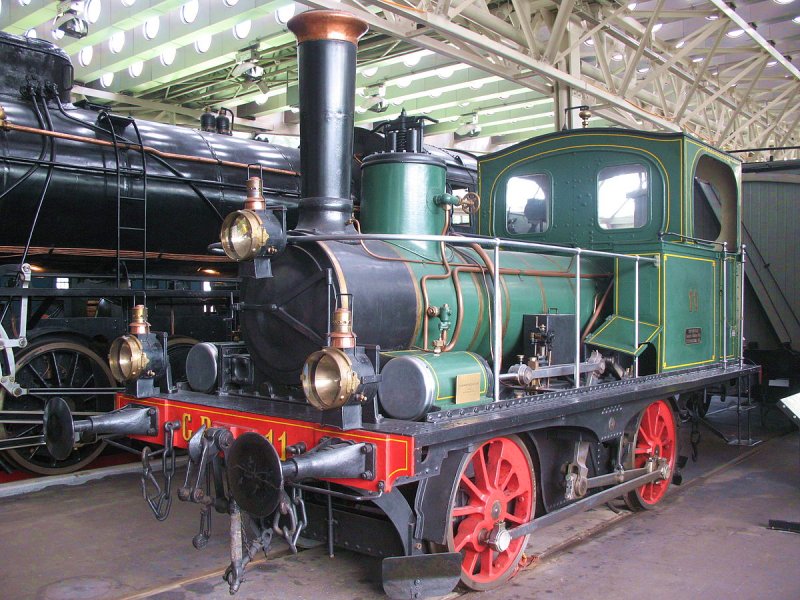 | Left: Lever locomotive 0-4-0 No 11: built 1881
|
I do not think that the Gotthard tunnel has bends, but since this first trip was made before the tracks leading to the tunnel were finished, a short and light-weight locomotive may have been highly desirable, and No 11 was very suitable.
The builder "SLM" was the Swiss Locomotive and Machine Works (in German: Schweizerische Lokomotiv und Maschinenfabrik) which was based at Winterthur, in Switzerland. One of its specialities was mountain railway equipment.
Surprisingly, the Swiss Locomotive Works was founded by an Englishman, Charles Brown. He was was born in Uxbridge, Middlesex, on 30 June 1827. In 1871 he left Sulzer in Winterthur, and formed SLM, famous for its tramway and rack locomotives. He was involved in the development of electric locomotives in the 1880s, and died on 6 October 1905 in Basle. He was the Brown in the well-known firm of Brown-Boveri
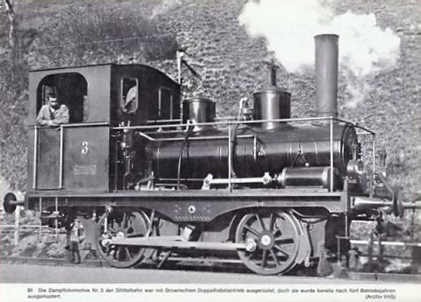 | Left: Another Systeme-Brown engine: built 1892
|
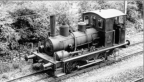 | Left: Another Systeme-Brown engine: date unknown
|
The question arises as to why the locomotives above were built the way they were. The system required two substantial levers, mounted on strong bearings to withstand the forces involved, and two more connecting rods; all bringing more cost, weight, and extra points for lubrication. Since the levers appear to have equal lengths above and below the central pivot, there would be no changes in piston speed or stroke compared with a conventional layout. The cylinders are raised well above the track by this method, possibly to keep them clear of dust and dirt? If anyone knows the answer I would be glad to hear it.
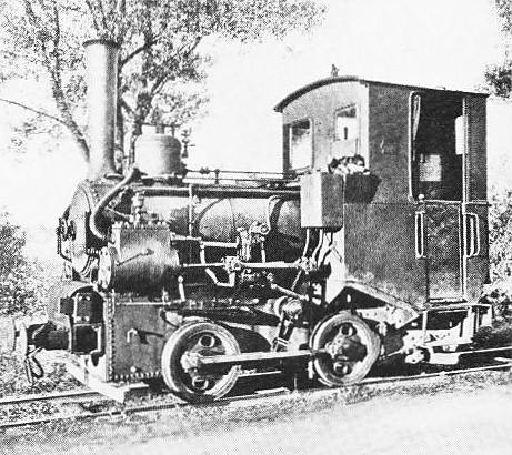 | Left: A German Systeme-Brown engine: built 1910
|
![]()
CORPET LEVER LOCOMOTIVES
Five 0-6-0 pannier-tank locomotives on the Brown system were built by L. Corpet of Paris, presumably under licence. They had the narrow gauge of 600mm. (1 ft 11-5/8 in) Similar locomotives were also supplied to contractors and West Indian sugar estates. Remarkably, three out of the five of them have survived. There's hope for the world yet.
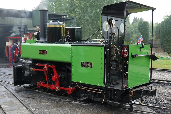 | Left: No 439 Minas de Aller at Statfold Barn
It lives at the Statfold Barn Railway in Staffordshire, where it has been restored to operating condition. Browns valve gear is fitted. The driver has to reach round the front of the cab to operate the regulator. |
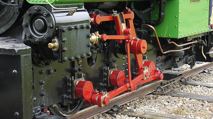 | Left: No 439 Minas de Aller at Statfold Barn
|
Of the three locomotives left, the only one working is No 439 at Statfold Barn; another (No 542, built 1891) is in the Museo del Ferrocaril de Asturias, (Railway Museum) in Spain, and the third (No 467, built in 1888) at Lousal in Portugal. It seems that Minas de Aller also built one themselves in their workshops. Aller is near Ujo, some distance south of Oviedo in Spain.
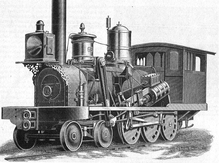
Here are two early Corpet-Louvet locomotives with Brown valve gear.
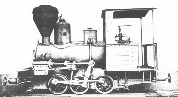 | Left: No 536, named E. EUSTACHE: 1890
|
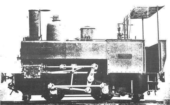 | Left: No 627, named 1 CHARLEVILLE,: 1895
|
![]()
 | Left: Camden and Amboy Railroad 0-8-0 'Monster': 1837
|
The inclined cylinders drove a front lever that in turn drove the third axle via a connecting rod with truss bracing. Only the third and fourth axles were connected by the coupling rod, the second axle being driven by gearing from the third axle; the second axle then drove the leading axle through another coupling rod. The front two axles were free to swivel to a limited degree, making the locomotive essentially articulated; this was the reason for the gearing between the two pairs of driving axles. These gears were highly stressed and there was trouble with teeth breaking off.
It has been said: "Both the boiler and running gear were marvels of independent, if not necessarily practical, invention."
Rather surprisngly, the C & A acquired five more Monster-clasa freight locomotives in 1852 and 1854. Nos. 33, 34, 42, and 43 were built by the Trenton Locomotive and Machine Company, while No. 35 was built at Bordentown.
 | Left: Rebuilt Camden and Amboy 'Monster': 1837
|
![]()
THE SNOWDON LOCOMOTIVES
A major user of lever-driven locomotives today is the Snowdon Railway in Wales. It is built to the common mountain railway of gauge of 800 mm (2ft 7.5in), and uses the Abt rack system. Its first five locomotives were built between 1895 and 1896, comprising: No 1 LADAS, No 2 Enid, No 3 Wyddfa, No 4 Snowdon, and No 5 Moel Siabod. LADAS was scrapped after being destroyed in an accident on the day the line opened. None of these locomotives were superheated.
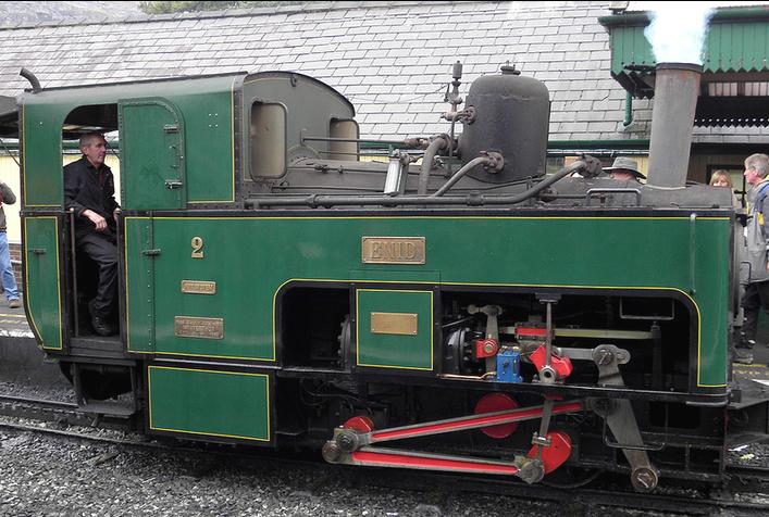 | Left: No 2 Enid on the Snowdon Railway
|
The boiler of Enid is inclined at an angle to ensure that the boiler tubes and the firebox remain submerged on the slope, as was usual for mountain steam locomotives. The locomotive goes chimney-first up the mountain, not turning around before backing down it, so the inclination is always the right way. The water gauge is set halfway along the boiler so the indicated water level does not change with gradient; this would seem to make it difficult to get at the vital gauge test cocks.
The use of lever drive is more explicable here. The wheels are very small, to get a high tractive effort, and there is probably not room to get a decent-sized cylinder in line with the axles. Also, the lever is proportioned so that the piston has a 50% greater stroke than it would have if directly connected to the wheels, giving presumably giving better cylinder proportions- longer and thinner rather than short and fat.
A later batch of steam locomotives: Padarn No 6, Ralph Sadler No 7, and Eryn No 8, were built between 1922 and 1923 with a different lever arrangement, as seen on Padarn below. The mechanism is fitted between double frames at the front, giving a more rigid arrangement. These engines were superheated.
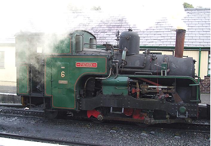 | Left: No 6 Padarn on the Snowdon Railway
|
Both series of locomotives use compression braking for the descent. The connections to the steam cylinders are altered so they become air compressors and convert mechanical energy into heat. Water is sprayed into the incoming air to cool the cylinders, so steam is emitted during braking.
Both series of locomotives were built by the Swiss Locomotive and Machine Works at Winterthur.
![]()
THE AIX-LES-BAINS RACK LOCOMOTIVES
 | Left: Aix-Les-Bains front-lever locomotive: 1892
|
Here the wheels are very small, and the proportions of the lever show that the piston stroke was about twice that of the crank throw.
![]()
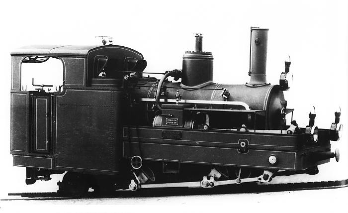
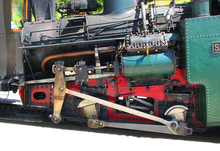
THE SCHAFBERGBAHN LOCOMOTIVES Z1 to Z6
The original steam locomotives on the Schafbergbahn (Schaf mountain railway) in St. Wolfgang, Austria, used bottom-pivoted drive-levers like "Enid" above. The locomotives were numbered Z1 to Z6. Z1 "Schneeberg", Z4 "Bergprimel" and Z6 "Berganemone" are still used for scheduled operation. Z1-Z4 were built in 1893, and Z5-Z6 in 1894.
 | Left: Locomotive Z4 on the Schafberg railway in St. Wolfgang, Austria
|
Once again the lever allows the piston stroke to be almost twice the distance of the crank throw.
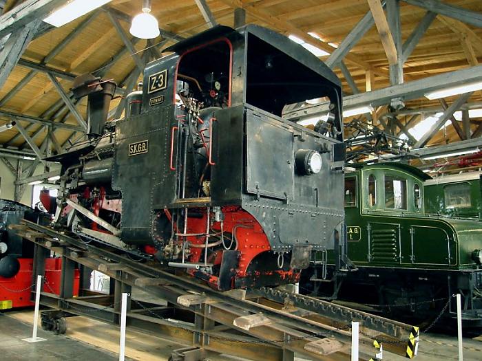 | Left: Locomotive Z3 on display at the Lokwelt Freilassing
|
BIBLIOGRAPHY
The standard textbook on Swiss locomotives is "Der Dampfbetrieb der schweizerischen Eisenbahnen" by Alfred Moser. (German Wikipedia)
![]()
THE BRIENZ ROTHORN BAHN (BRB) LOCOMOTIVES
The Brienz Rothorn Bahn (BRB) is a tourist railway in Switzerland, that starts at the eastern end of Lake Brienz. There is some info on the railway here and they have an official website here
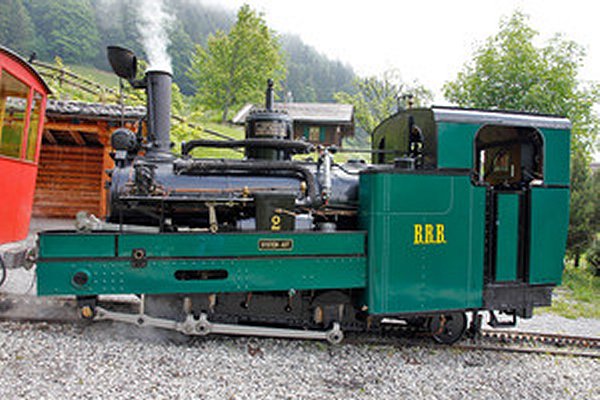 | Left: 0-4-2 lever locomotive of the Brienz Rothorn Bahn
|
![]()
![]()
THE PIKES PEAK LOCOMOTIVES
There is a well-known mountain in the USA called Pike's Peak, home to the Manitou and Pike's Peak Railway. (aka the Pikes Peak Cog Railway) This has gradients of about 1:6 with some sections at 1:4, and is worked using the Abt rack system. Gradients of 1:4 are close to the upper safe limit for the Abt system. The Baldwin Locomotive Works built a number of lever steam locomotives for the line. All had their boilers set at an angle to make them horizontal in use.
Construction of the railway began in 1889 and the first three locomotives were delivered in 1890, with three more arriving later.
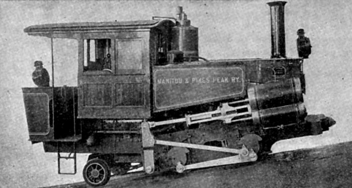 | Left: Baldwin lever locomotive for Pike's Peak
|
On the preserved locomotive seen here the lever is pivoted at the bottom, and drive goes to the front axle. The piston stroke is almost twice the distance of the crank throw.
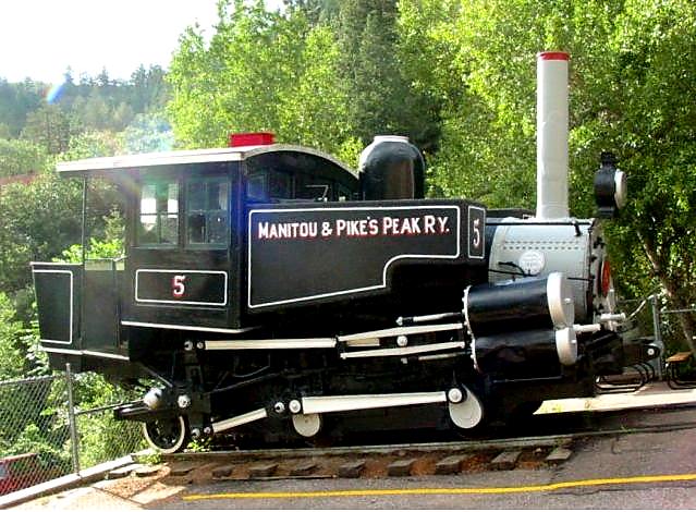 | Left: Pike's Peak No 5 locomotive
|
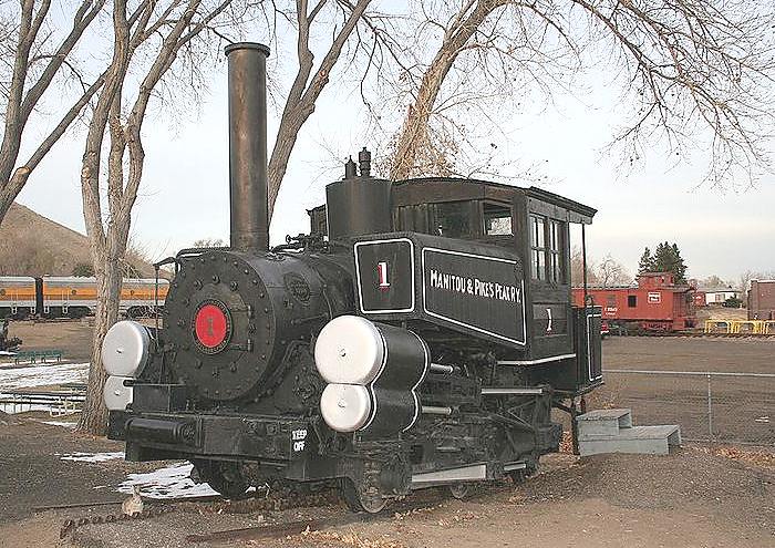 | Left: Pike's Peak No 1 locomotive
|
For Russian lever-drive locomotives, (some with jackshafts too!) see the Russian Reforms gallery.
![]()

|