THE KRUPP-ZOELLY TURBINE OF 1928

Above: The Krupp-Zoelly condensing turbine locomotive T18-1001.
The 6-stage forward turbine developed 2000 hp at 6800rpm. The reverse turbine had 3 stages. Delivered to the LVA (Locomotive Testing Plant) in 1928. Withdrawn after being hit by a bomb in 1940.
 |
| Left: Side elevation of the T18-1001
|
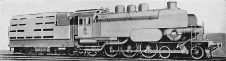 | Left: The T18-1001 locomotive with its original "streamline casing" in place.
The casing was later removed for easier maintenance. This was the usual fate of locomotive shrouds and casings.
|
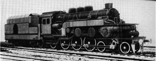 | Left: Another picture of the T18-1001 locomotive.
|
 |
| Left: The smokebox arrangements of the T18-1001 locomotive.
The diagram shows the feedwater heater wrapped around the inside of the smokebox, and the draught fan, driven by a small steam turbine.
Note that there are actually two chimneys, the smaller one at the rear apparently being used in conjunction with a steam blower set below its petticoat; presumably this gave more draught than the fan, and was used when raising steam had priority over economy. This chimney would need to be closed off during normal fan operation, and there appears to be a butterfly valve set in it just above boiler level.
|
 |
| Left: Head-on view of the fan draught arrangements of the T18-1001.
The fan and its volute exit casing was offset from the centre-line of the boiler.
The vertical thing mounted on the bottom of the smokebox appears to be a steam blower; see above caption.
|
THE MAFFEI TURBINE OF 1928

Above: The Maffei condensing turbine locomotive T18-1002.
The locomotive T18-1002 was delivered to the DRG in March 1929. By 1934 the locomotive had covered 60,000 km.
Steam pressure was 323 lb/sqin. In spite of the higher boiler pressure the Maffei was less economical than the Krupp.
It was withdrawn when damaged by bombing in 1943. The boiler was used for safety-valve testing until it was scrapped in 1961.

Above: Side elevation of the T18-1002
THE HENSCHEL TURBINE TENDER OF 1927
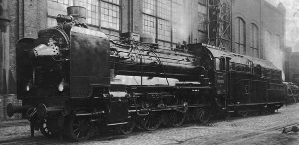 |
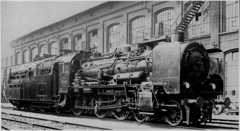
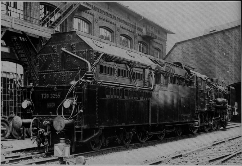
| Left: The T38 piston-turbine condensing locomotive.
The T38-3255 was essentially a conventional piston-driven steam locomotive, exhausting into a LP turbine booster in the tender. The turbine exhausted in turn into a condenser at the rear of the tender, offering the potential for efficient turbine operation. It was designed by Dr Zoelly of the DRB in association with manufacturer Henschel.
|
Above: Side elevation of the T38 locomotive. Note the large exhaust duct from the turbine to the condenser, which is the sort of thing you need for reasonable turbine efficiency.00:04 21/05/2004
Most of the innovation was in the tender. This was built by Henschel at Kassel in 1927. The locomotive was almost standard apart from the addition of fan draught. Tests were run in late 1927, and the results were not encouraging. Again there are reports that excessive power was lost in windage in the reverse turbine; this presumably means that the condenser vacuum was poor. The reverse turbine was therefore removed, as the piston-driven loco was perfectly capable of moving a train in reverse. There also appear to have been problems with excess steam consumption by the auxiliary machinery; presumably this means the various fan drives.
In 1937 the locomotive was converted back to normal operation and given a conventional tender. It was eventually scrapped in March 1961.
Above: The T38 without the conical nose that held the draught fan.

Above: The rear of the turbine-driven tender of T38. The two coupled driving wheels connected to the jackshaft can be seen under the front of the tender.
|
Above: The front section of the T38 turbine tender.
The front section of the tender contained the turbine and coal storage; the rear section held the condenser. In the diagram above the pipe at lower right carries the locomotive exhaust to the turbine; the large circular duct at left is the turbine exhaust to the condenser.
|
 |
| Left: Cross-section of the front part of the T38 turbine tender.
The large circular duct in the centre is the turbine exhaust to the condenser in the rear of the tender.
|
 |
| Left: The fan-draught system of the T38.
In this attack on the fan-draught problem, the exhaust gases are turned through 180 degrees by a curved inlet diffuser, and then directed through a right-angle to go up the chimney. The large shaped plug just behind the fan is an exit diffuser to increase fan efficiency.
The large U-shaped depression above the fan held what appears to have been a feedwater heating tank.
|


