Updated: 6 May 2008
ASME paper added
Another picture added


The Armstrong-Whitworth Turbine-Electric Locomotive. |
Updated: 6 May 2008 |

|
Above: The Armstrong-Whitworth Turbine-Electric Locomotive. Apologies for poor picture quality. |
This steam-turbine-electric locomotive was designed by Mr D M Ramsay, managing director of the Ramsay Condensing Locomotive Company of Glasgow. While it is not yet formally confirmed, this chap is almost certainly the "Ramsey" involved in the earlier Reid-Ramsey Turbine Locomotives.

The locomotive was built by Armstrong-Whitworth of Newcastle-on-Tyne, and delivered to the Lancashire and Yorkshire Railway in 1922. The wheel arrangement was 2-6 + 6-2; each half had six coupled wheels driven by a jackshaft with two 3-phase electric motors geared to it; each motor could produce 275hp. Most of the weight was therfore available for adhesion.
The front unit carried the boiler; beneath it was a compound turbine direct-coupled to a 3-phase AC generator. 890kW at 600V 3-phase was delivered at 3600rpm. The rear unit carried fuel, water, and the air-cooled rotary evaporative condenser. The condenser was fitted to create a sufficient exhaust vacuum for efficient turbine operation rather than to save water.
Above: Side view of the Armstrong locomotive. Note the air-flow reversing cowling (or "air scoop") at the rear.
One of the infelicities of this design was the need to reverse the direction of the air so it would flow forwards through the rotary condenser and then upwards through the exit ducting. This reversal must have caused some loss of air flow, and I speculate that this may be one reason why the condenser proved unequal to the task of providing a suitable exhaust vacuum for the turbine.
The turbine was an impulse multi-stage compounded type made by Oerlikon of Zurich, driving a three-phase generator through a flexible coupling; the generator was excited by a DC generator driven by an auxiliary turbine. The turbogenerator combination was installed under the boiler, giving a high centre-of-gravity, (though this not unequivocally a bad thing with locomotives) and restricting the boiler size. This may have limited the steam-raising capacity.
Here are some nuggets of hard fact:
This picture was almost certainly taken at the same time as the one above, but I have no definite information on that point. At any rate, the standard lamps look the same. Note the interested crowd at far left.
The grilles just above platform level are cooling air vents for the control resistors.
The support for the front of the boiler can be seen to the right.
AN ASME PAPER ON THE ARMSTRONG-WHITWORTH LOCOMOTIVE
Here is an abstract (from RAILWAY AGE, dated January 10, 1925) of a paper presented at the annual meeting of the Railroad Division of the American Society of Mechanical Engineers by George F Jones and T Laurence Hale:
"There is great room for improvement when it is considered that a locomotive of the ordinary type has a thermal efficiency of only approximately six per cent and that doubling its, thermal efficiency would reduce the fuel consumption by half or alternatively, allow a much more powerful locomotive to be built with the present practical limits of firebox area.
The replacing of cylinders by the steam turbine is an innovation, in locomotive construction, but not more so than the application Qf condensation which is rendered possibie by lts introductlon. From a thermodynamic point of view, it is evident that turbo locomotives, whatever their systems of power transmission, whether electrical or gear, largely depend for their economies in fuel consumption upon the efficiency and reliability of their condensing plant.
General Description
Each portion of the locomotive carries two driving motors, each pair of motors being bolted to a center cross-bearer which carries a transmitting shaft and spur wheels. Pinions are keyed to the motor shafts and these mesh with the spur wheels, the power being finally transmitted through coupling rods from the spur wheels to the driving wheels in the ordinary manner. The spur wheel and pinion shafts are enclosed in a gear case and run in an oil bath. The gear ratio is 2.8 to 1.
The main turbine is of the impulse type and contains. nine stages. The mean blade diameter is 36 in. It IS designed for a steam pressure of 200 lb. per sq. in., and the steam IS superheated to a total temperature of 685 deg. F., exhausting to a vacuum of 27 in. The turbine is flexibly coupled to a three-phase alternator and has a speed range of 1,800 rpm at starting to 3,600 rpm. at 60 miles an hour. The three-phase alternator. is designed to develop 890 kw. at a maximum pressure of 600 volts.
The auxiliary turbine is a single stage machine flexibly coupled to a direct-current generator, which provides the energy for the excitation of the main alternator poles as well as for the auxiliary direct current motors driving the condenser fan, condenser rotor, condenser extracting pump and the forced draft set for the boiler. It also supplies the necessary current for lighting the train. The auxiliary turbine operates under the same steam conditions as the main turbo set.
The boiler is of the ordinary locomotive type and the combustion chamber is supplied with air by a high speed forced draft set located in the cab. A simple locking device is provided on the fire door to prevent a blow-back, the door being prevented from opening by a safety catch when the forced draft fan is in operation.
The transmission of power from the main turbine to the driving motors is three-phase, current being supplied from the alternator to the four alternating current slip ring motors, each motor having a continuous output capacity of 275 b.hp. and one hour's rating of 360 b.hp.
The following tractive force is developed at the rims of the driving wheels for the acceleration period from rest to 60 miles an hour:
Design and Description of the Condensing Plant
Further experiments were carried out on a plant containing some 400 sq. ft. of surface. For the sake of simplicity, the condensing surfaces were composed of ordinary brass condenser tubes and, as a natural development to facilitate the process of filming, they were arranged in the form of a circular cage, or hollow drum. The drum, supported between bearings, was rotated in a tank containing water, the tubes passing through the water as they rotated. The condenser was supplied with air by an axial fan and was tested in conjunction with a steam regenerator and the necessary wet air pump, water filming of the surfaces and resultant evaporation taking place successfully. The promising results from this experimental work led to the design and construction of the present locomotive condenser.
Control of Power and Speed Regulation
Principal Dimensions And Proportions
Shop and Main Line Testing
Here is a larger version of this drawing where the dimensions are mostly legible.

Left: The Armstrong-Whitworth at Manchester, in 1922 or 23.
Overall Length:
69ft 7in
Wheelbase:
59ft 4in
Fixed Wheelbase:
16ft 4in
Driving Wheel diam:
48in
Heating surface incl superheater:
1453 sq ft
Grate area:
28.4 sq ft
Steam conditions
200 psi, 300 degF of superheat
Turbine speed
3600 rpm
Generator
890 kW at 600V 3-phase, 27.5in vacuum.

Left: The Armstrong-Whitworth taking on water.
Picture from Engineering 24 March 1922?

Left: The rear of the Armstrong locomotive, with the air-flow reversing cowling removed, revealing the fan, which was supplied by the Peter Brotherhood company. The condenser itself was built by Mirrlees-Watson.
Picture from Engineering 24 March 1922.
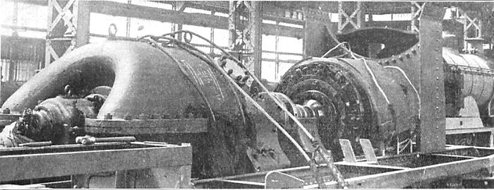
Left: The turbo-generator being assembled on the locomotive frame.
Picture from ASME 10 Jan 1925.
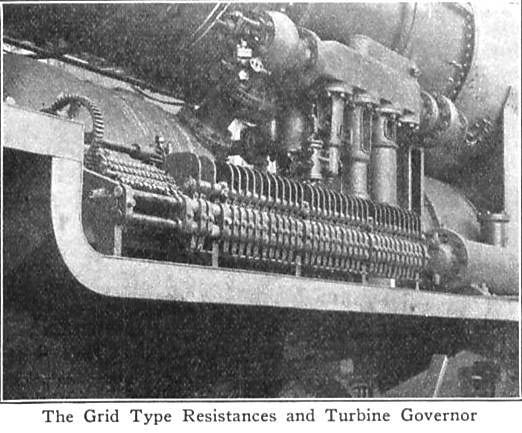
Left: The turbo-generator governor and grid resistances.
Picture from ASME 10 Jan 1925.
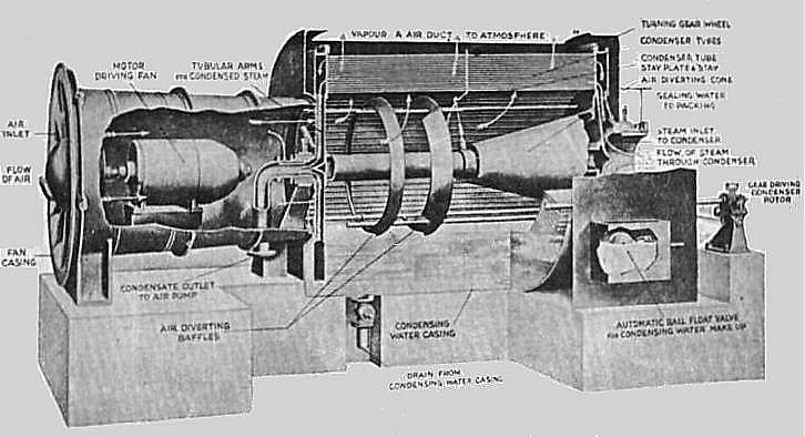
The front portion of the Ramsay locomotive, which is connected to the rear portion by a special universal joint, incorporates the boiler, forced draft set and driver's cab, the main turbo-alternator set and the auxiliary direct-current turbo generator being situated under the boiler. The rear portion of the locomotive is practically devoted to the condensing plant with axial fan, condensate extracting pump, etc. Room, however, has been found for the main water tank and coal bunker. Communication between the turbines and condenser is by means of a 24-in. diameter exhaust pipe which is provided with a flexible rubber connection reinforced by internal rings of aluminum.
Miles an hour Tractive force
At starting 22,OOO lb
15 22,000 lb
30 11,050 lb
60 8,600 lb
60 (normal running) 6,000 lb
As the success of a locomotive of this description depends in such a large measure upon the design and action of its condenser, it is perhaps not irrelevant to give a very brief review of the groundwork which influenced the adoption of the principle of evaporation as the basis of design for the present condenser.
In the light of previous experience with the difficulties of recooling condensing systems, it was decided to attack the exhaust steam by direct means. It was fully realized that the alternative method to evaporation, that of direct cooling by air alone, involved the employment of large condensing surfaces and excessive fan power, and that such a type of condenser would depend for its success largely upon atmospheric conditions; and, while probably producing a satisfactory vacuum in low temperature countries, the system would be at a great disadvantage and far from satisfactory in hotter climates. Attention was, therefore, turned towards evolving a suitable condenser on the direct cooling system based on the evaporative principle as being the system to successfully meet the atmospheric conditions of all countries.
In design, the ordinary evaporative condenser has progressed but little and still remains practically as originally conceived; such test results as existed were unreliable and it was, therefore, necessary to carry out a series of preliminary experiments on small scale condensing apparatus with fans to produce a current of air and so intensify the evaporative effect. The importance of maintaining a thin and unbroken water film upon the condensing surfaces was easily demonstrated and, of the numerous methods and contrivances tested with a view to producing satisfactory water filming of the surfaces under a blast of air, the simple method of completely immersing the surfaces in water before exposing them to the air current was found to give the most reliable and proper film effect. Repeated tests on a small condensing plant proved the type to be exceedingly economical in water consumption, in practice approximately only one pound of water being evaporated to condense one pound of steam. The fan power required was reasonably lowwhile the rate of heat transmission was found to be moderately high and sufficient to bring the condensing surface well within the practical limits.
Ordinary condenser practice was observed in the con- struction of the drum which consists of an annular nest of standard % -in. diameter brass condenser tubes ferruled into two headers. The exhaust steam entering one header is condensed, and the resultant condensate is collected and drawn off from the other header and returned to the hot well by the rotary extraction pump as hot clean feed water for the boiler. The trunnions of the respective headers are fitted with air tight glands of the steam sealed self-adjusting type, and this design of gland has given satisfaction in resisting air leakage into the condenser.
A small motor, driving through a spur gear, turns the drum which is housed in a sheet metal casing, the bottom of which forms a tank containing water fed from the main tank for purposes of filming, and a pneumatic float maintains the water at a constant level. The condensate extracting pump is of the ordinary rotary condenser design, while the air pump is of the steam ejector type and has two stages. This pump is supplied with steam from the bOiler through a reducing valve.
Before starting the locomotive, the auxiliary turbine is run up to a speed of 3,000 r.p.m., thus providing excitation for the main alternator and energy for the motor-driven auxiliaries. The main turbine set is then run up to half speed; viz, 1,800 r.p.m. At this period the motors are connected in cascade by the master controller in the driver's cab. Then the locomotive may be started.
It is well known that when a turbine speeds up from rest to full speed, its torque decreases in the ratio of two to one, and when passing through the period of half speed its torque is one and one-half times the normal and this is the torque of the main locomotive turbine when running at starting speed; namely, 1,800 r.p.m. Again, two alternating current motors when connected in cascade and running at half the alternator speed, have twice the turning moment that they have when connected in par- allel with the same power consumption. Therefore, with the driving motors in cascade and the main turbine running at half speed, the torque from rest to quarter speed will be two times 1.5, or three times the normal torque. The motors now being connected in parallel with the turbine running at half speed, the speed of the locomotive increases from one quarter to one half speed, and the torque becomes 1.5 times the normal. The turbine speed is then increased to the maximum and the torque drops from 1.5 times the normal to normal.
In controlling the speed of the Ramsay locomotive from rest to 60 miles an hour, the following sequence of operations is observed:
After the main and auxiliary turbines have been brought to speed by means of the hand wheels in the cab which control the steam inlets, all control of the locomotive is carried out electrically by means of the master controller. To start the locomotive, the controller wheel is moved to the first notch, thereby closing the excitation circuit of the alternator and connecting the driving motors in cascade with resistance wholly in circuit. Further movement of the control wheel cuts out resistance until a first running position of 15 miles an hour is obtained. If a greater speed is desired, the controller wheel is further moved round and changes the motor connections from cascade to parallel, and the excitation circuit being again closed, the motors once more operate under current, resistance being cut out until a second free running speed of 30 miles an hour is reached.
Further increases of speed are obtained by moving the controller wheel round, step by step, whereby the setting of the main turbine governor is correspondingly altered, that is, the speed of the turbo-alternator is increased and thereby the periodicity. In this manner the speed of the locomotive can be increased from 30 to 60 miles an hour. A reduction in the speed of the locomotive is obtained by turning the controller wheel quickly back to the zero position, thus observing the reverse succession of operations to those of starting up to full speed. The excitation circuit being opened, the motors are without current and ready for starting up again in cascade.
Reversing the locomotive is, of course, effected by reversing the driving motors in the ordinary way. The illustrations show the general arrangement of the front portion of the locomotive. The resistances, which are of the grid type, are arranged under the running plates on either side. Both vacuum and Westinghouse brake equipment is used.
Length overall 69 ft. 7 in.
Total wheel base 59 ft. 4 in.
Rigid wheel base 16 ft. 4 in.
Drivlng wheel diameter 48 in.
Height from rail to center line of boiler 10 ft. 3 in.
Maximum width 9 ft. 0 in.
Total heating surface of boiler 1,543 sq. ft.
Grate area 28 sq. ft.
Tractive force at starting 22,000 lb.
Shop tests, to ascertain the reliability of the special electrical control were carried out before the locomotive was given actual running trials. In addition, several main line trials were made when the locomotive hauled heavy trains without difficulty, a vacuum, ranging from 80 to 95 percent, being regularly attained and held. Pronounced smoothness of running was evident, due to the constant and even turning moment exerted by the driving motors.
At no time during the run did the temperature of the condenser exceed 135 degF which corresponds to a vacuum of 25 in. of mercury. Improvement in the vacuum during easier periods of the run were noted. The work of driving and firing was carried out by ordinary railway employees and, as all the work in speeding up the locomotive is performed electrically, the duties of the engineman, so far as controlling the locomotive is concerned, are confined to the turning of the controller wheel, while the duties of firing are not as onerous as those connected with the ordinary locomotive.
It is difficult- no, impossible- to reconcile this optimistic report with what actually happened on trials, as described above.
NOW READ ON for more than anyone needs to know about the rotary evaporative condenser.
To begin with, here is a picture of its internals. This is the actual machinery before it was fitted to the Armstrong-Whitworth locomotive.
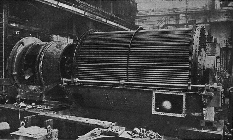
One of the many problems with steam turbine locomotives is that a condenser is pretty near mandatory to get good efficiency. This is a large piece of hardware to drag around. An ordinary air-cooled condenser just blows air past the tubes; however size and weight can be much reduced by using an... Evaporative Condenser. Such a device increases heat transfer greatly by keeping the tubes exposed to the air wet, so the latent heat of evaporation of the water is utilised as well as direct conduction to the air. The evaporation naturally causes some loss of water, but this is much less than in a non-condensing loco which throws all its exhaust steam away.
The magnificent piece of hardware above works thus: the big cylinder is made up of the condensing tubes. It rotates slowly in a water-bath, the water thereof being kept at the right level by the big ball-cock at lower right. Steam enters via the flange on the extreme right, and the fan to blow the air over the tubes is in the big circular bit at the left. The diagram below shows the internals.
 | Left: Showing how fan power needed to increase with incoming air temperature.
|
Cooling surface5030 sq ft
Condensing rate15,000 lbs/hr
Water temp120 degF max
Air pump2-stage steam ejector
Average vacuum26 in Hg
Fan driveDC electric motor |
![]()

|