 |
| Left: The Swiss Eb3/5
This machine was full of clever innovations, but regrettably must be one of the ugliest locomotives ever designed. Only one was built.
The two cowls at the front of the boiler protect the firebox air intakes; presumably from snow.
|
This 2-6-2 tank engine was built at Winterthur by the Swiss Locomotive and Machine company at the end of 1927, to the design of Mr Buchli, their chief engineer.
The boiler worked at 850 psi and was supplied by a compound feedpump, which had its own small superheater in the firebox. The feedwater was preheated to 180 degF by the exhaust steam of the main cylinders and the feedpump, and then further heated to 450 degF by the feed heater at the front of the boiler.
The air to the grate was preheated by a heat exchanger at the front of the smokebox. How combustion gases were induced to pass through this is obscure.
The water-tube boiler consisted of a top drum and two bottom drums, connected by water-tube walls.
 |
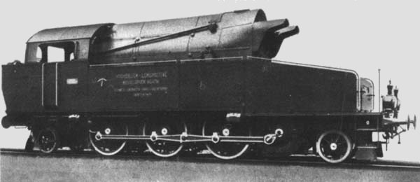
| Left: Side elevation of the Eb3/5
This gives a good view of the positioning of the engine in the nose. The crossbow-shaped thing on the side of the tank is a water-level indicator.
|
The totally-enclosed engine had three cylinders with cam-driven poppet valves and uniflow exhaust ports.The camshaft was operated by bevel drive from the crankshaft. The crankshaft drove the jackshaft through 1 to 2.5 flexible reduction gearing.
Extensive trials were made in Switzerland and Austria, and it was also tested on the network of the l'Est in France, where it impressed observers, and inspired the French 232-P-1 high-pressure loco. It was claimed that it produced 40% more work for the same fuel than a conventional loco, and that 2.25 lb of coal and 15 lb of water per DHP-hr were used when 800 HP was delivered at the drawbar.
During trials it was reported that most of the scale was deposited in the feedwater heater, which was the intention, but some was formed in the boiler tubes, which could have been very dangerous. The builders are said to have believed they had a cure, but the locomotive was not heard of again. Perhaps the problem, like the scale, was insoluble.
Nothing further is known about the fate of this project.
Above: The internal arrangements of the Eb3/5
 |
| Left: The Swiss Eb3/5 firebox viewed from the rear.
1 Steam drum11 Grate bars17 Main feed heater27 Feed pump control
2,3 Bottom drums 12Insulation 18 Clack valve28Feed pump superheater
4,5,6 Water walls 13 Safety valve 19 Smokebox29 Compound feed pump
7 Water tubes 14 Regulator 20 Air heater30 Feed preheater
8 Stay tubes 15 Main superheater 23 Blast pipe33 Water tank
9 Firebox 16 Stop valve 25 Ash outlet35 Engine
10 Combustion chamber 26 Ash outlet 36 Exhaust
| | | | | | | | | | | | | | | | | | | | | | | | | | | | | | | | | | | | | | | | | | | | | | | | | | | | | | | |
These numbers refer to all three diagrams.
|
Above: The firebox and boiler of the Eb3/5
The new pictures below have just been discovered, and are believed to be unique to this website.
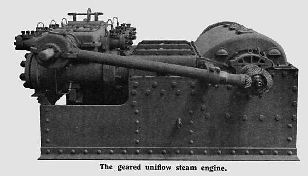 |
| The three-cylinder uniflow engine of the Eb3/5
Note the angled shaft to drive the valve camshaft, with skew bevel gears on the crankshaft end.
|
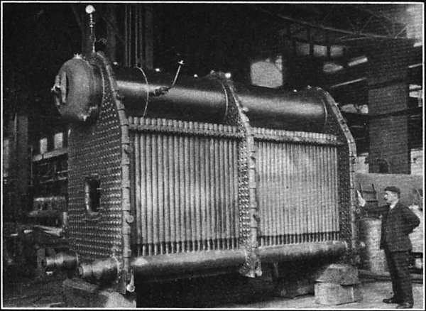 |
| The boiler of the Eb3/5
Judging by the pressure gauge at top left, the boiler is probably here undergoing a hydraulic pressure test.
|
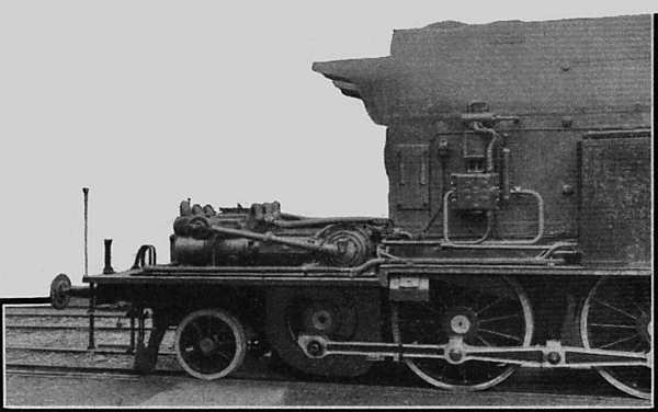 |
| The Eb3/5 with the hood over the engine removed
The jackshaft is just below the engine crankcase. Accessibility for maintenance looks good...
|
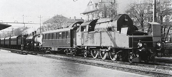 |
| The Eb3/5 on test
The Eb3/5 is marshalled in a train with a conventional locomotive at the left, probably as insurance in case of a breakdown.
The angular structure at extreme right looks like a shelter for technicians taking indicator diagrams. The two cowls at the front of the boiler seem to be missing.
Date and location unknown.
|


