This little-known Swiss locomotive was the first serious turbine design to be built, by SLM/Escher-Wyss/Zoelly in 1919. For some reason it fails to appear in most locomotive books.
It was a conversion of an elderly 3/4 locomotive of the Federal railways. (see bottom of page for a picture of the original type) The "3/4" is the old German/Swiss axle classification system, indicating 3 driven axles from a total of 4. Thus a 4-6-0 and a 2-6-2 are both 3/5, which is not too helpful.
The new locomotive had a 6-stage Swiss Zoelly impulse turbine located transversely in front of the smoke box, a separate 2-stage Curtis turbine being used for reverse. Steam supply was controlled by two sets of valves. The main turbine developed 1200 HP and drove the coupled wheels through two stage reduction gearing with a ratio of 1:28, a jackshaft and coupling rods. Turbine speed was 7500rpm at the planned maximum speed of 75 km/h.
Felix Brun tells me there seem to have been three different versions of the condenser:
1) The first was a surface condenser under the boiler.
2) This appears to have been unsatisfactory as it was replaced by two long surface condensers on the sides, where the steam went through condenser tubing surrounded by water.
3) This was again replaced with two surface condensers mounted lower on the sides. Now the water went through the condenser tubing; this is the normal practice in condensers for power stations, etc.
On the tender at first there was a natural draft waterspray cooler that was later replaced with a forced draft version with a seperate Turbine to drive the Fan. Two surface condensers were placed on either side of the boiler, using cooling water from the tender. This water was returned to the tender by turbo-pumps. The boiler, of the usual locomotive firetube type, had a working pressure of 170 psi.
A condensing system naturally prevents the use of a conventional blast-pipe for boiler draught, and this was at first supplied by means of a cold-air blower beneath the grate. This very unusual arrangement avoided having a suction fan working in exhaust gases at 300 degC, an approach which gave trouble in many subsequent condensing locomotives, but meant that the firebox was at positive pressure and the blower had to be stopped every time the fire needed feeding.
This highly dangerous system (one hopes the blower and fire-door were interlocked, but history is silent on this point) was soon replaced by a draught fan mounted on the smokebox door.
The German Krupp-Zoelly Turbine Loco of 1922 was a development of this locomotive, a significant difference being a larger condenser housed in the tender.
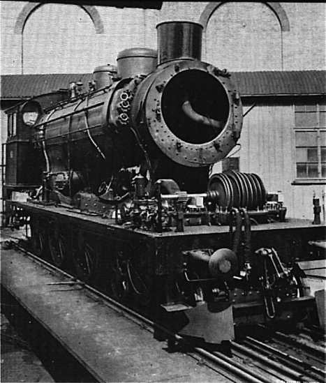 |
| Left: The Swiss turbine loco under construction: 1919
The turbine shaft with its blade discs can be seen just in front of the smokebox.
Bibliography: Un.
|
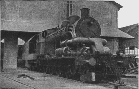 |
| Left: The first version
This rather enigmatic picture appears to show the locomotive just after its completion. There is a long structure on the side of the boiler that appears to be the second sort of condenser mentioned above. There are three intriguing pipes leading into/out of it.
The smokebox door looks normal, so this is before an extraction fan was installed. The large duct just below is clearly the turbine exhaust, which is split in two and sent to the rear, though exactly where is hard to say. Possibly the first condenser was still installed under the boiler at this point?
From Modern Power Engineering, by A Regnauld, pub Caxton 1924. Vol 1, p15.
|
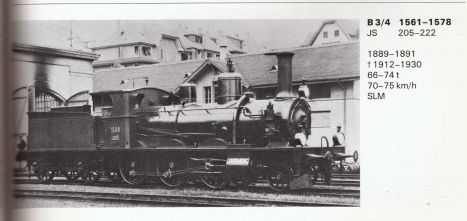 |
| Left: The original 2-6-0 locomotive looked like this.
It was clearly a radical conversion; very little appears to have been unchanged.
|
 |
| Left: The first trial of the condensing system
The first version of the condenser appears as cylinder beneath the exhaust duct.
The turbine draught fan has not yet been fitted to the smokebox.
|
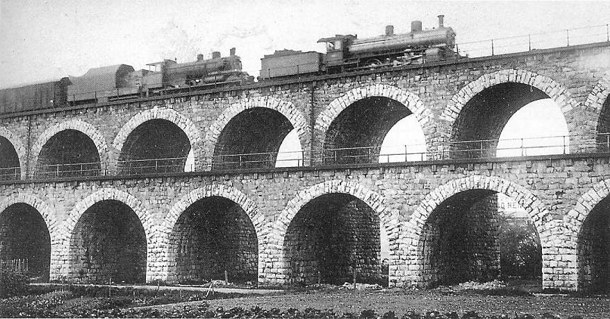 |
| Left: The locomotive on the Aussersihller viaduct
The turbine locomotive is on the left. The first version of the condenser is in place.
|
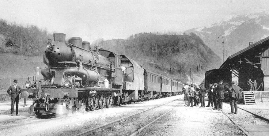 |
| Left: A test and measurement run
Here the second version of the condenser is fitted, with the exhaust duct leading directly into the end of the cylindrical condenser
|
 |
| Left: The locomotive on a turntable at an unknown location
The second version of the condenser is fitted.
|

The following pictures show the locomotive with the third type of condenser installed.
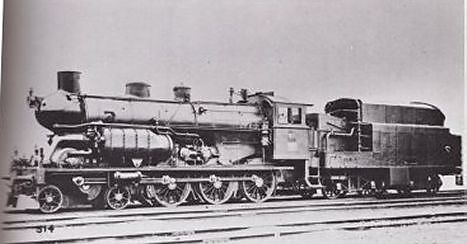 |
| Left: The Swiss 3/5 turbine locomotive
The weight was 115 tons and the planned speed 75 km/h.
The third version of the condenser is fitted.
|
 |
| Left: The 3/5 Swiss turbine locomotive in steam
Note surface condensers (third version) each side of the boiler. These were cooled by water from the tender; this water was itself cooled by intimate contact with the air as it was sprayed from a series of pipes in the tender. Considerable water was lost in this process, and the overall water consumption was only improved to about half that of a conventional locomotive.
The perforated streamline nose held a turbine-driven draught fan; the suggestive pipe visible running into this casing may have been the fan steam supply, but this is speculation.
|
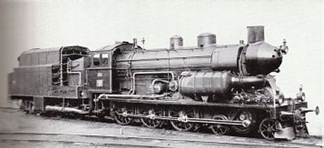 |
| Left: The locomotive seen from the other side.
This is probably one of the official photographs, and gives a good view of the jackshaft drive. This cutting-edge locomotive still has an oil lamp on the front. Note the unusual shape of the cooling tender.
The third version of the condenser is fitted.
|
 |
| Left: Side elevation of the Swiss turbine 3/5.
This gives a better view of the cooling tender.
|
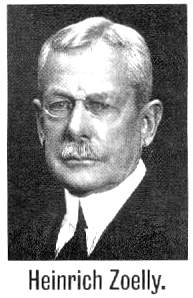 |
| Left: The man behind the turbine: Heinrich Zoelly
Heinrich Zoelly was a was a Mexican-Swiss engineer, who developed steam turbines and turbine-driven locomotives. He was born in Mexico in 1862. His father, originally from Klettgau in Switzerland, had emigrated to Mexico to better himself. Zoelly died in 1937 in Zurich.
He has a Wikipedia page.
|


