Updated: 17 Oct 2014
New:
Anonymous Engine revealed


Anonymous Engine revealed
Water Engines: Page 2 |
Updated: 17 Oct 2014
Anonymous Engine revealed |
WESTGARTH AND SMEATON: 1765
According to A Textbook of Mechanical Engineering, by Wilfred J Lineham, (1912), the first hydraulic piston engines in England were introduced by Armstrong in 1838. However... a little research soon showed that this is quite wrong. Immediately below is shown the Westgarth-Smeaton engine below, built in 1765; this was probably the first water engine constructed in Great Britain. There is also the Mainwaring engine below, which must have been built before 1835, as it is described in The Engineer's and Mechanic's Encyclopaedia by Hebert, which was written in that year.
See Victorian Water Engines
for more on Armstrong and his innovations.
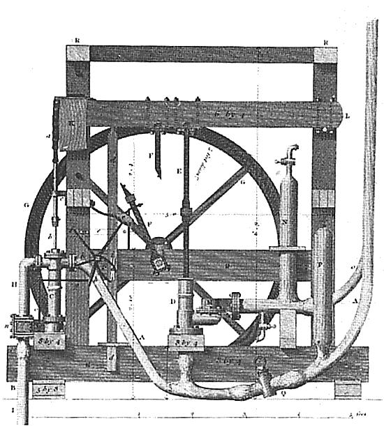 | Left: The Westgarth-Smeaton water engine: 1765
Unfortunately the function of the various parts is none too clear. D is the engine and C is the pump, er, or it might be the other way round. There should be three pipes leading to the machine; the supply of water to power it, the exhaust water leaving the engine, and the delivery pipe for the water being lifted, but only two are visible. |
My best guess is that there are actually two pipes on the right, one behind the other, rather than one with a Y-junction at the bottom. One is the supply and the other the pump delivery. If that is the case, then C is the engine, with exhaust at B, and D is the pump. The water supply comes in via pipe A, is controlled by the plug-cock at Q, and then splits to feed the engine C and the pump D. N is an air-vessel to absorb pulsations in water delivery, and P is a similar vessel to cushion sudden changes in water demand as the engine valves work. The spidery arrangement to the left of the crankshaft may be some sort of valvegear for the engine section.
Note the connecting rod F, joining the beam L to the crank of the flywheel G; this is arranged so it can be disconnected in the middle. The side elevation below shows a big handle which must be for hand-pumping when the power water supply fails. As later parts of this page show, a flywheel is not essential to a water engine, but might be desirable to steady hand pumping.
It looks as though there might be another (closed) disconnector in rod E. I am by no means sure my interpretation of the parts is right- it is possible that C is the pump and D is the engine. If that's so, the second disconnector would be to uncouple the engine cylinder when hand pumping was in use.
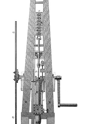 | Left: side elevation of the Westgarth-Smeaton water engine: 1765
|
After the middle of the eighteenth century, power-driven pumps were in common use to drain the greater part of the mine systems below the level of the main drainage adits. (Adits are near-horizontal tunnels used for drainage by gravity- they can only drain that part of a mine above a valley floor) With exquisite irony, extensive use of water power for pumping meant that during droughts the water supply failed and the mines could flood. To try to prevent this extensive networks of waterways and dam ponds were built. Ice could also be a problem in the winter.
Steam was found to be very expensive to operate compared with hydraulic engines, which were almost as effective and much cheaper; in the era before railways coal was difficult to transport and was consequently expensive to use in areas distant from coal mines. There are several cases on record of Newcomen-type engines being installed but later abandoned because of prohibitive fuel costs. An example is the Wheal Rose mine in Cornwall, where an engine was installed in 1727, but the fuel costs were so high that the proprietors found it more economical to drive a 1.5 mile drainage adit and discontinue use of the engine. [Palmer}
A steam engine also required constant supervision from skilled men, and even given that a boiler explosion was always an interesting possibility. Surprisingly perhaps, the economic advantage of water engines persisted for many years, well into the railway era; for example, by 1872 the last of the steam engines at the Derwent lead mines in the Pennines had been replaced by a water pressure engine.
 | Left: An early water engine: pre-1835
|
 | Left: Operational Details of The Mainwaring engine.
|
 | Left: Operational Details of The Mainwaring engine.
|
 | Left: Operational Details of The Mainwaring engine.
|
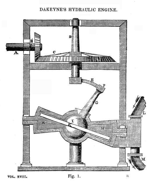
| Left: The Dakeyne disc engine: 1820s
|
For considerably more detail see this remarkable website: The Romping Lion: Dakeynes Disc. (external link)
| Left: The Dakeyne disc engine
|
Wikipedia has a brief article on the Dakeyne hydraulic disc engine.
Several steam disc engines working on the same principle were built at later dates.
MR DEANS' ENGINE: 1830
A Mr Deans of Hexham erected several water engines, which were described by Weisbach as "simple and efficient". He built a water engine at Wanlockhead, in Scotland, in 1830 or 31. It had a fall-bob (whatever that is) for working the valves. [Weisbach]
The descripton below is taken from a letter by a Mr John Dolphin, of Hunter House, Hexham, to The Mining Journal, dated Saturday 2nd December 1837. It appeared on Page 181.
Letter: Water Power.
"Sir, - An article appeared in your Supplement to the Mining Journal, of September 9th, extracted from the Greenock Advertizer, and headed "Water Power," which I did not particularly notice at the moment, but subsequently, at a meeting of the Northumberland Agricultural Association, at Hexham, it was brought more immediately to my recollection by Mr. W. Deans, an engineer of that place. I observe the article in question to be, a discovery of a new application of water power - that it consists of a cylinder and piston similar to those employed in a steam-engine - that advantage is taken of the pressure of water, which gives it a force of 60lbs to the inch, the entrance and discharge pipes being of equal sizes, and the number of strokes sixteen in a minute, with the cylinder placed in a vertical position - and that the discoverer had made another model with the cylinder laid horizontally, and with the discharge pipes nearly three times as large as the entrance ones; and by this means the motion was increased to twenty-six double strokes in the minute. I think it of great importance that any useful discovery in mechanics should be made as public as possible, and that the author should have all the merit it deserves; and I hold it to be equally just, that where such a claim is publicly set up, without the merit of a discovery, that it should be as publicly exposed.
"I have been connected with very extensive lead mines in the north of England for more than thirty years, and have known the same application of water power used in some of them, for pumping and other purposes, during all that time. The first engine of that description used in England, was at a lead mine, belonging to T.W. Beaumont, Esq., called Coal Cleugh, in Northumberland, and was erected about fifty years since, by Mr. Westgarth, who obtained a medal from the Society for the Encouragement of Arts, Manufactures, and Commerce; and I believe, it is at work to this day. The next engine, of the same description, of which I have any knowledge, was used at a lead mine called Crash Purse, near Chesterfield. A plan of this engine was taken by Mr W Deans, an engineer employed at the Derwent Lead Mines, in the County of Durham, in 1810, and one was erected by him at these mines, which has continued working up to this time. The engines I have named were of single power, taking in the water on the top of the piston only. About fourteen years since, another engine was required at the Derwent Mines, and Mr Deans was directed to make it of greater power; he therefore applied himself to improve upon his former plan, and put up a very powerful engine at the Jeffries Rake Lead Mine, on the same principle as a double-powered steam-engine - this was the first application of the pressure to both sides of the piston, and it was found to be a great improvement.
"In 1831, the Marquis of Bute requiring some additional pumping power in his lead mines at Wanlockhead, and having learned that a great improvement had been made in the construction of water pressure engines, at the Derwent Lead Mines, sent an agent there to inspect them, , and on his report determined to employ Mr Deans to erect one, which was done in the early part of 1832, and which superseded the use of two very expensive steam-engines. Last year he put another for the same nobleman, at the same mines, and as the space for the cylinder, if placed in an upright position, required to be cut out of very hard rock underground, at a great expense, he devised the method of placing it horizontally, and in doing so discovered that he could also simplify the machinery attached for pumping. Both these engines are now in use at Wanlockhead Lead Mines, and I presume the Greenock tradesman must have seen them. Mr Deans is now at work with one for the Scotch Mining Company, at Lead Hills mines, adjoining to Wanlockhead; and he is also preparing one of a greatly improved construction, intending to give it a rotative motion, for the purpose of applying it as a drawing engine."
Note that Mr Deans' water engine "superseded the use of two very expensive steam-engines."
Note also that the writer claims that performance was greatly improved by making "the discharge pipes nearly three times as large as the entrance ones" which seems a bit strange, as water is notoriously incompressible.
MORE ALPORT WATER ENGINES: 1842
Six water engines were erected at the Alport lead mines, near Bakewell in Derbyshire, to the design of Mr Darlington, the Alport mine engineer. They were constructed under a Mr John Taylor of the Butterly Iron Company. (According to SciMusLib John Taylor was the actual designer) Whether these engines replaced the Trevithick water engines at Alport because they were worn out or for some other reason is curently obscure.
![]()
![]()
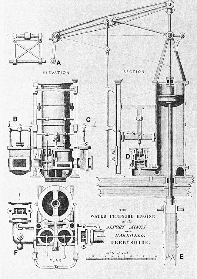 | Left: Alport engine
|
 | Left: Another early water engine
|
![]()

|