WATER ENGINES ELSEWHERE
That is, not in Great Britain.

THE PRATT & WHITNEY ENGINE: 1876
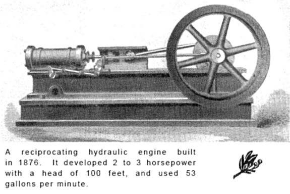 |
| Left: Pratt & Whitney water engine
This engine has what appears to be an oscillating valve just below the cylinder. The aperture below it may be the water exhaust, its central position relative to the cylinder suggesting that the engine was double-acting. 100 feet head of water is equivalent to 43 psi.
It is not possible to see if the stroke was adjustable.
From the Pratt & Whitney History Book, Part 2
|
According to Knight's American Mechanical Dictionary, (1881) two forms of engine were made by Pratt & Whitney; one of them was a reciprocating engine working with water at 20 psi, and intended for working printing presses, etc. The stroke was adjustable from 4 to 10in to control the power output.
This is not the same Pratt & Whitney who now make jet engines; the Pratt & Whitney Aircraft Company was started with capital and factory space provided by the Pratt & Whitney Machine Tool Company, who made the water engines, and many, many other things from typewriters to rock drills. They are now Pratt & Whitney Measurement Systems Inc. The aircraft company was allowed to use the Pratt & Whitney name, but they have always been two different companies.
My thanks to Kerry Stiff and Ed Culver for pointing this out to me.
The Pratt & Whitney Machine Tool Company also built prototypes, of which the most famous is the Paige typesetting machine, in 1889 and 1890. The prolonged and unsuccessful development of this machine cost Mark Twain at least one fortune. Nontheless, its design formed the basis of the Mergenthaler Linotypeand other typesetting machines developed later.
THE PERRET ENGINE: 1881
 |
| Left: Perret's hydraulic engine
This French engine was double-acting, with a standard piston arrangement at p. The interesting feature is the annular arrangement for water inlet and exhaust at each end of the cylinder, presumably intended to give the maximum port area and therefore the fastest possible operation.
From Knight's American Mechanical Dictionary, 1881.
|
Perret's working cylinder a is completely surrounded by another cylinder containing the input water; this is surrounded in turn by an outer cylinder for the exhaust water; the middle and outer cylinder are a single casting b fixed to the frame. The inner cylinder is moved back and forth inside the casting by an eccentric on the crankshaft, set 90 degrees behind the crank; this opens and closes the inlet and exhaust ports. Water inlet is through pipe i, and exhaust is via pipe c.
THE SCHMID ENGINE
The Schmid engine was introduced by of Albert Schmid (1847-1915) a Swiss mechanical engineer. He spent some time in England, Russia and Austria; in 1870 he returned to Zurich. There he participated in the city council's plan for the construction of a pressurized water supply network. Water motors with an output of 1/3 to 3/4 hp were used to pump water up to high-level service reservoirs. The engines wee exhibited at the World Exhibition in Vienna in 1873, and won awards.
 |
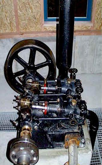
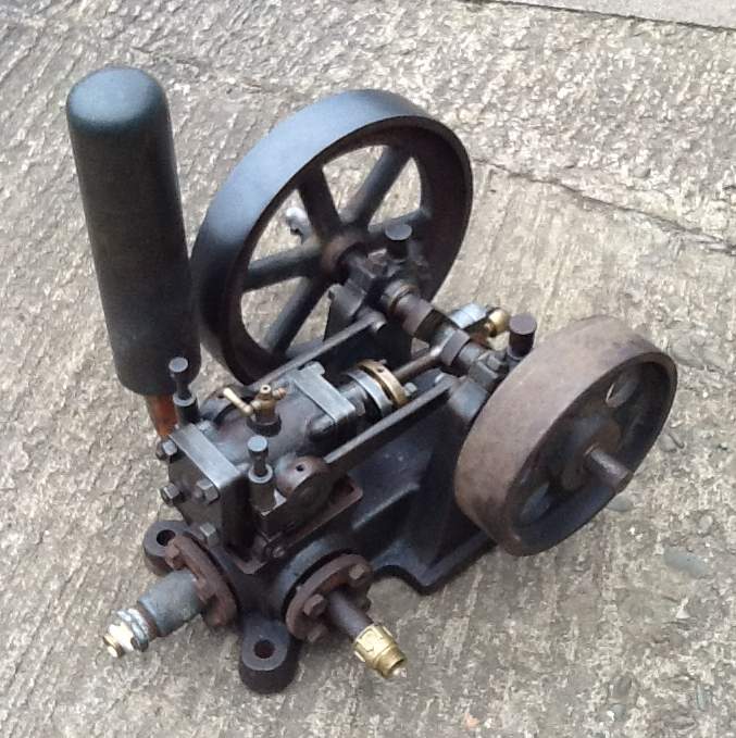
| Left: Diagram of a Schmid engine with oscillating cylinder.
This engine is not identified in the source, but it clearly corresponds with the second drawing below. Having said that, there are some intriguing differences; the flywheel of this drawing has six spokes instead of four, and so on. It appears to be a cleaned-up version with added errors. (the part of the trunnion support lever to the left has been omitted)
As with the Ramsbottom, the valve arrangements are very simple, probably because there is no need to allow for any variation in cutoff. The ports are are in the curved part at the bottom of the cylinder, once more covered and uncovered as the cylinder(s) oscillate. Water comes in through the pipe under the cylinder, and exhausts out to the left.
A good fit between the cylinder and the stationary part of the valve was maintained by mounting the cylinder trunnions on levers at each side, pivoted near the crankshaft bearings. These were pulled down by an adjustable screw which can be seen to the left of the second drawing below.
From The International Library of Technology, Hydraulics Volume, 1920. Pub Scranton International Textbook Co.
|
The purpose of the three small fittings on the top of the cylinder is obscure. The two at each end are most probably some kind of relief valve, but the larger one in the middle is a puzzle. If it is a lubricator, what induces the oil to flow inwards against all that water pressure?
 |
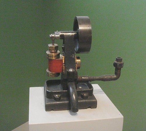
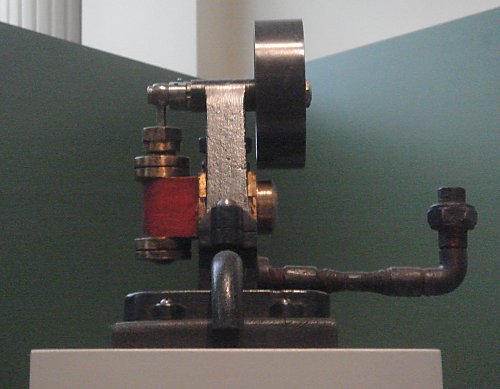
| Left: A Schmid engine with oscillating cylinder.
Not brilliant picture quality, I'm afraid, but it does show (sort of) some extra details. The trunnion support lever adjusting screw is at extreme left.
One common factor in these engines is the small throw of the crank compared with steam engines. This is presumably because of the greater piston force produced by hydraulic pressures of 800psi, much greater than the common steam pressures of 50 - 150 psi. As there was no expansion, this pressure was also maintained for the whole of the piston stroke.
The structure at top left is probably an air chamber to reduce shocks as the amount of water drawn from the supply main varies.
From Knight's American Mechanical Dictionary, 1881.
|
 |
| Left: An operational two-cylinder Schmid engine in Rothenberg
Probably a unique photograph. This is one of two preserved Schmid engines at the Altes Wasserwerk pumping station in Rothenberg, which from 1902 until the 1960s supplied the villages of Rothenberg, Ober-Hainbrunn, and later Kortelshütte with water.
Power water comes from 40 metres above the pumping station, and water is pumped up 280 metres from the Gammelsbachtal valley to the Rothenberger High reservoirs.
The engines were manufactured by the Maschinenfabrik Schmid in Zurich. The first engine-pump unit was installed in 1902, the other in 1904, allowing alternate operation and thus a continuous water supply during maintenance work and repairs.
Power water comes in through the grey pipe at bottom right, and exhausts through the black pipe to the extreme right. Note the air chamber at upper right. As usual, the two cranks are set at 90 degrees.
Each cylinder has two associated handwheels working on the trunnion support levers to control the pressure on the valve; this is a more compact arrangement than that shown in the first two pictures above. The aim is to allow a small amount of water leakage- enough to lubricate the bearing without excessive waste of water. The piston-rod gland is a stuffing-box packed with knitted yarn impregnated with tallow.
The copyright status of this image is uncertain. I have tried to contact someone at Rothenberg, to no avail. If anyone feels I have infringed their rights then please let me know at once. I'm sure we can work something out.
|
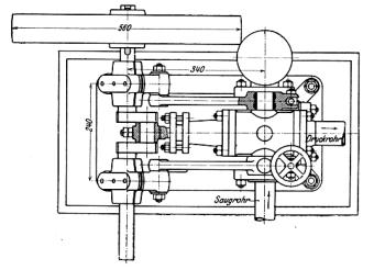 |
| Left: Plan view of a single-cylinder Schmid engine, with dimensions.
At least, I'm pretty sure it is. The two pipes are labelled in German "suction pipe" and "pressure pipe" which sounds as if it was a pump. However, in every other respect it looks like a single-cylinder Schmid engine.
The trunnion support levers can be seen pivoted just to the right of the crankshaft. Note the adjusting handwheel on the lower trunnion support lever. The upper bearing is shown in section so only the spindle of the handwheel is visible.
|
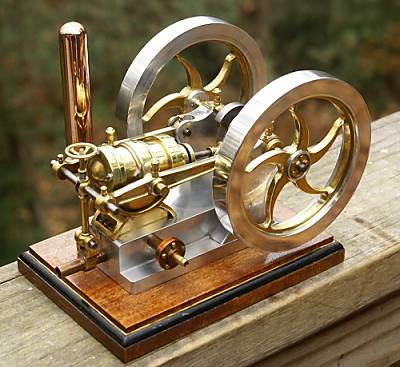 |
| Left: A beautiful model single-cylinder Schmid engine.
This fine model is based on the version with the longer trunnion support levers, seen at the start of this section. You can see a Youtube video of the model running on compressed air.
Note the copper air chamber to absorb hydraulic shocks.
The builder's website, with many more engine models, can be seen at http://www.cedesign.net/steam/schmidt.htm.
|
 |
| Left: Another view of the model single-cylinder Schmid engine.
Here the trunnion support levers have been disconnected from the adjustment screw and the cylinder raised to show the valve ports.
|
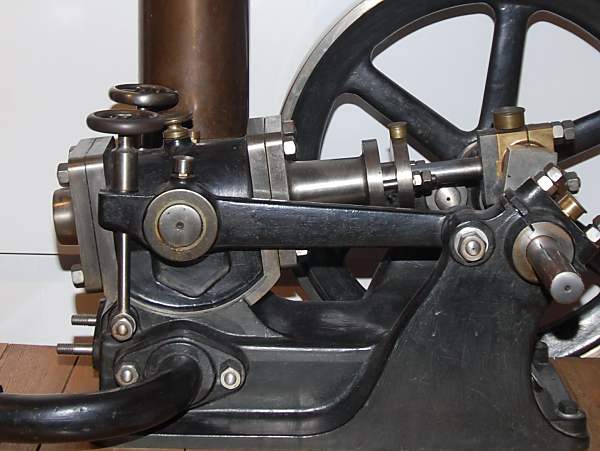 |
| Left: Another preserved single-cylinder Schmid engine
A close-up of a Schmid engine in the Deutsches Museum, Munich, showing the trunnion support levers and their adjustment handwheels. The copper thing at top left is the shock-absorbing air cylinder.
Picture kindly provided by Anthony Shipman
|
 |
| Left: And another preserved single-cylinder Schmid engine
This is a small model, delivering an estimated 1/4 HP.
The Dimensions:
Bore 1 9/16 ", Stroke 2", Flywheel diameter 9 3/4", overall length 14 1/2".
There is no makers plate or serial number anywhere on the engine. The grease cup on the big end bearing is by Stauffer of Germany.
The tie bars holding the cylinder down have ends suitable to accept a bar to tighten them rather than hand wheels. A light pressure is used, minimising friction and allowing a little water seepage to aid lubrication of the port face. Note the small air lock release cock on top of the cylinder.
Picture and details kindly provided by Robin Storey
|
 |
| Left: Single-cylinder Schmid engine up for auction
This Schmid engine was put up for auction in 2019; it is not known if it sold or how much for. The flywheel diameter is 23 in, the overall size is 47 x 27 ˝ x 32 in.
The thing like a chimney in the middle of the picture is an oddly-shaped air reservoir.
|
 |
| Left: Single-cylinder Schmid engine up for auction
This is the only Schmid engine I know of with a governor; it is at the left, acting on a valve in the inlet pipe below, and is driven by pulleys from the crankshaft. Presumably there are flyballs inside the mushroom-shaped thing. The handwheel just below sets the speed.
|
THE COATES & LASCELL ENGINE: 1881
 |
| Left: A Coates & Lascell vertical water engine.
Once more, not brilliant picture quality, I fear.
This description is given in Knight's American Mechanical Dictionary, 1881
"The valve shown at B C is balanced and self-packing. The induction-port a is located at one end, in one of two transverse discs b at the end of the valve. These fit closely the interior of the valve-chest c, and are connected by a flat plate d. A hollow trunnion e admits the water, which flows in the direction of the arrows into the valve-chest. A curved plate f, having openings g serving as eduction-ports for the valve, diffuses the pressure. An orifice h, opposite the hollow trunnion admits water back of the disk nearly balances the end-pressure of the valve, only sufficient excess of pressure being allowed to pack the washer which keeps the joints from leaking. This pressure may be relieved, if necessary, by means of the set-screw i. An auxiliary pipe and valve k, opened by means of a separate eccentric, are arranged to give an additional supply of water when the piston has traversed one fourth of the length of the cylinder, so as to equalise the motion of the crank."
The last bit is rather opaque, but may refer to an attempt to minimise variations in torque on the output shaft. It is also not too clear where the valve goes on the main picture.
Note the importance of making the valves balanced when using such high pressures; otherwise operating friction would be excessive.
From Knight's American Mechanical Dictionary, 1881.
|
A WATER ENGINE IN VIENNA: 1900
 |
| Left: Single-cylinder oscillating-cylinder water engine: 1900
Small double-acting water engines of this type were used to drive sewing machines in Austria around 1900. Water enters through the pipe at right and leaves through the pipe at bottom centre. The overall height is about 8 inches. Note the drip tray around the bottom of the engine.
This example is in the Vienna Technology Museum.
Author's photograph
|
 |
| Left: Single oscillating-cylinder water engine: 1900
The engine from another angle.
Author's photograph
|
UNKNOWN WATER ENGINE: 19??
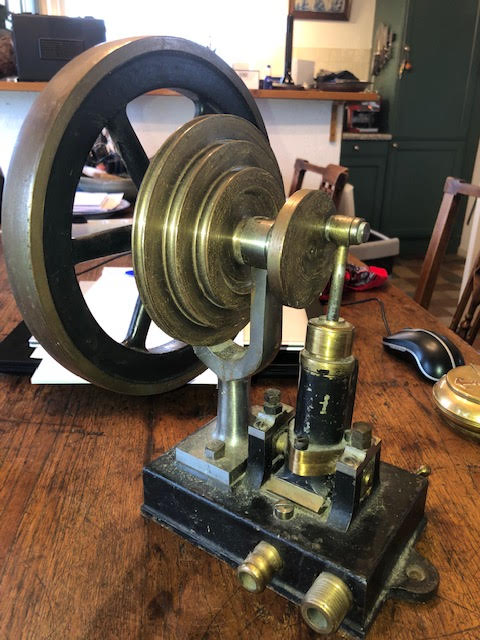 |
| Left: Single oscillating-cylinder water engine: 19??
This engine has no markings on it and its provenance is unknown. It is a vertical-cylinder version of the Schmid concept, with the valve ports at the bottom of the cylinder. Either side of the cylinder trunnions are nuts to adjust the pressure of the cylinder against the base.
The multiple pulleys suggest it was built for general purposes and not one specific application. It runs well on 0.5 Bar water pressure.
Can anyone provide more information?
|
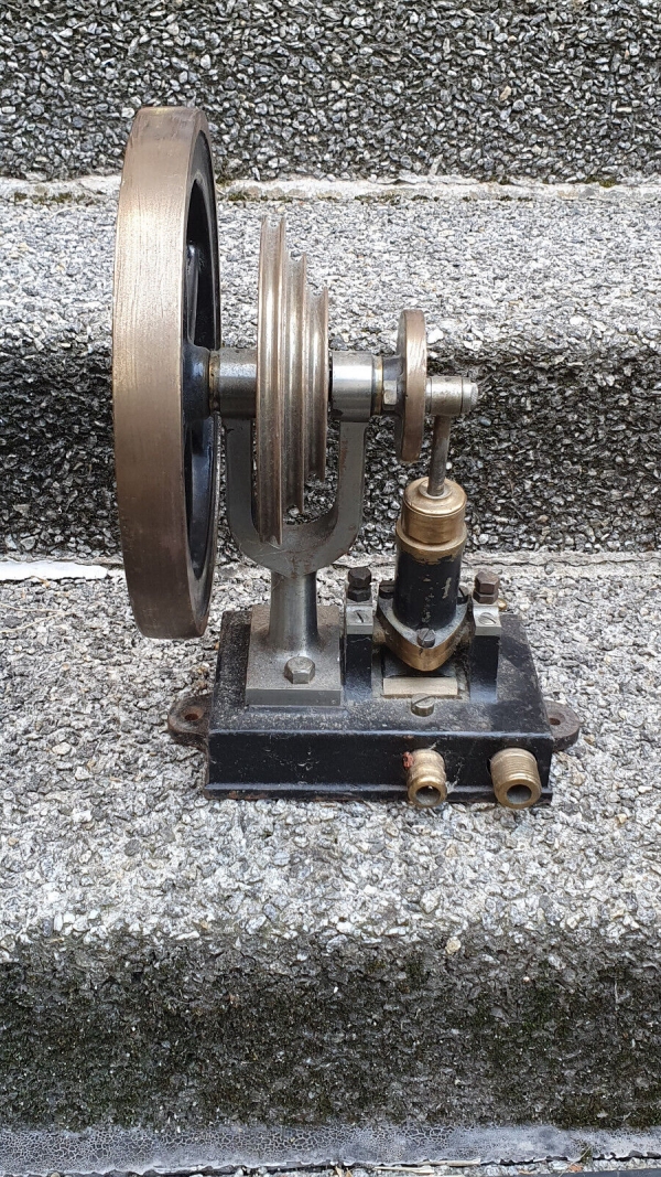 |
| Left: Single oscillating-cylinder water engine: 19??
Another view. Note the nuts on each side of the cylinder trunnions for adjusting bearing pressure are fitted with lock-nuts.
|
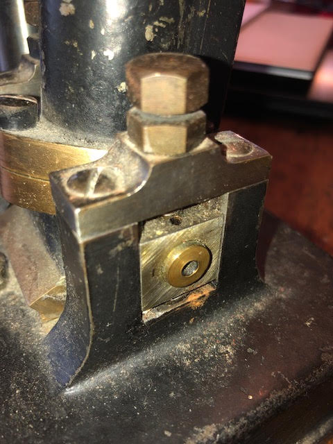 |
| Left: Single oscillating-cylinder water engine: 19??
Close-up view of screws for adjusting bearing pressure, with lock-nuts.
|
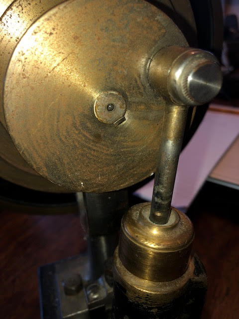 |
| Left: Single oscillating-cylinder water engine: 19??
Close-up view of piston and crankwheel.
|
THE WATER-POWERED DANISH RESPIRATOR
In 1931 a water-powered mechanical respirator was designed by the eminent Danish physiologist August Krogh after seeing a Drinker respirator in the USA. Krogh's version was not powered by electricity like Drinker's machine; it was was powered by water from the city pipelines, probably because the water supply was considered more reliable than the electricity in 1931. Reliability of the power supply is of course absolutely crucial. It is likely that the power unit was a water engine with pistons, in view of the relatively slow operation required, but it could have been a water motor (Pelton turbine) geared-down substantially. Apparently the respirator was simply connected to an ordinary tap, so only modest amounts of water can have been required.
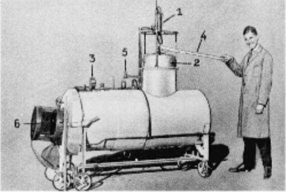 |
| Left: The Krogh respirator: 1931
The respirator was not widely used, apparently because of a lack of knowledge on when artificial ventilation would be useful. The first three patients were suffering from barbiturate poisoning, and the fourth neurosyphylis.
Apologies for poor picture quality. Deliberately damaged by Wiley. Nice.
|
More information can be found in the article "Two Early Danish Respirators Designed for Prolonged Artificial Ventilation" by H. Sund Kristensen and M. Lunding in Acta Anaesthesiologica Scandinavica Volume 22, Issue Supplement s66, pages 96–105, March 1978. This is available in several places but apprently not without your being bled for money by big publishing firms.
Krogh was awarded the Nobel prize for physiology in 1920.
A GERMAN WASHING MACHINE POWERED BY WATER ENGINE: pre-1948
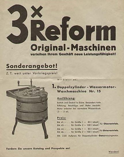 |
| Left: German ad for a water-powered washing machine: 19??
The water engine appears to be the horizontal cylinder on top of the tub, but this remains to be confirmed. At the moment it is not clear if the paddle action was rotary or back-and-forth. The ad says "The motor is worked by normal water-pressure".
This application of water engines was brought to my attention by Rainer Wilking, who says: "... my mother and grandmother used a water-driven washing-mashine until the end of the 1950s: the so-called 'wasser-motor'. It was a widespread device in Germany in the 1st half of the 20th century and I wonder if it wasn't known in the rest of Europe. It was made of solid wood and the water-motor activated 4 paddles hanging from the top of the lid and moving the clothes in hot water with soap or detergents."
Adolf Jaeger has told me: "The price is in RM (Reichsmark) which was the currency of Germany until 20 June 1948. The script, in its entirety, uses the characters of the Latin alphabet, which was mandated in 1942, before which the Gothic alphabet was in general use."
So the advert is from before 1948.
|
SOME OTHER WATER ENGINES
These are described in Knight, and appear to have been American in origin: no pictures are currently available.
1) The Stannard hydraulic engine resembled a small horizontal steam engine. Length of stroke was adjustable from 4 to 8 in. Cylinder diameter was 5 in.
Both of these engines appear to have had adjustable cranks to vary the stroke; since there is no mention of them having the complicated arrangements of the Rigg or Hastie engines, it is assumed that adjustment could only be made with the engine stopped. This would allow the engine to be matched to a fixed load, and thereby economise on water usage, but it could not have adapted to load variations in use.


