Gallery opened: Nov 2006
Updated: 15 Mar 2018
London Hydraulic Company pump


Water Engines: Page 5 |
Gallery opened: Nov 2006 |
DOMESTIC SUPPLY PUMPING
 | Left: A domestic water-powered water pump.
In fact, the control of this device presents an interesting problem; if the water tank in the roof was prevented from over-filling by the usual ball float and valve, when the valve closed the pump would stop and no water could be drawn in the kitchen. The control lever probably circumvented this impasse by allowing the engine cylinder to work without operating the pump, but if so it is not clear from this illustration. |
THE ROBERTS PUMP: 1902
The Roberts pump was produced in America, probably between 1890 and 1912; US patent No 715,871 was issued to George J Roberts of Dayton, Ohio in December 1902. The pump was intended to use high-pressure mains water, of unacceptable quality, to pump purer water from another source, such as a well or rainwater storage up into a tank as an alternative supply. Rain-water would be much softer and better for domestic use. It had two cylinders and very much resembled a duplex boiler feed-pump. It was patented and introduced by George J Roberts of Dayton, Ohio. Other things were happening in Dayton, Ohio at the time.
 | Left: Drawing of the pump
|
You can see an example working (powered by compressed air rather than water) on Youtube. The version seen has duplex power and pumping cylinders and dates from around 1910.
 | Left: A horizontal water-powered pump
|
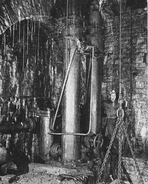
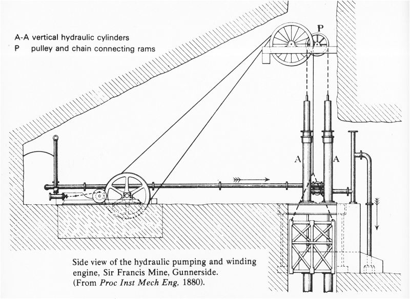 | Left: Hydraulic winding-engine and dual hydraulic pump at Sir Francis mine
|
NOTE: This drawing is identical with that in The Principles, Construction and Application of Pumping Machinery by Henry Davey, where it was stated that it was installed in the A D lead mine near Richmond, Yorkshire. However the drawing closely echoes the Sir Francis photographs below, and it would appear that the two installations were virtually identical.
One of the lift cages can be seen lower right. The vertical features behind it appear to be the pump rods, presumably driving force pumps at the bottom of the shaft.
 | Left: General layout at Sir Francis mine
|
 | Left: The dual hydraulic pump at the Sir Francis mine
|
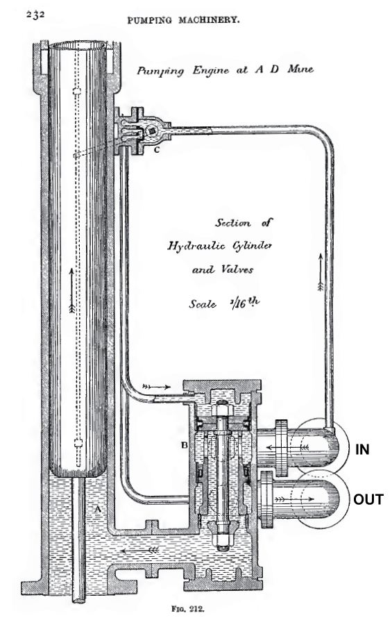 | Left: Section of one of the pump cylinders at the Sir Francis mine
|
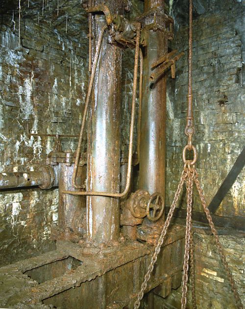 | Left: Hydraulic pump at Sir Francis mine: 1996
|
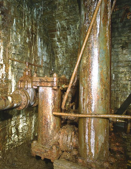 | Left: Hydraulic pump at Sir Francis mine: 1996
|
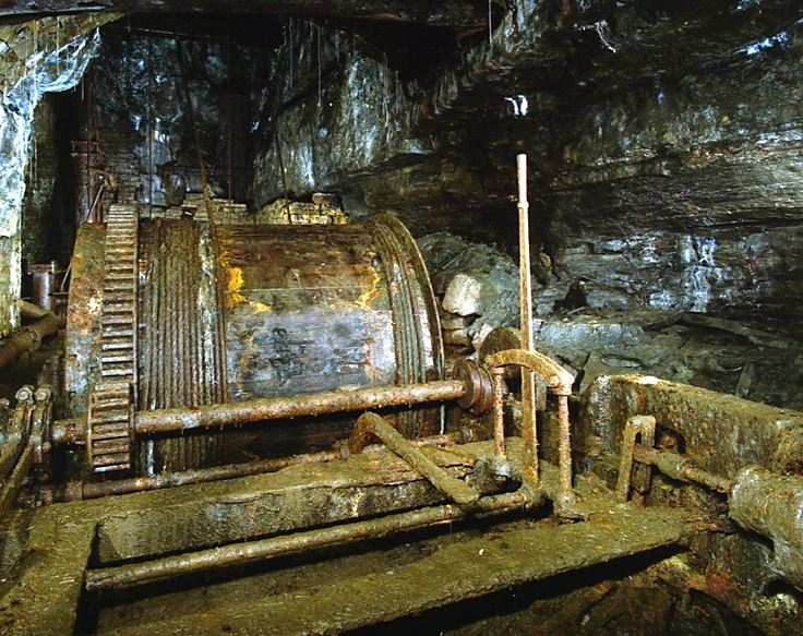 | Left: Hydraulic winding-engine at Sir Francis mine: 1996
|
 | Left: Hydraulic winding-engine at Sir Francis mine: 1996
|
The engine, winding drum, and pumps are still in position today.
HATHORN-DAVEY HYDRAULIC MINE PUMPS
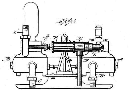
 | Left: Water-powered water pump for mine drainage: 1877
|
The company had made earlier engines in which the engine had slide valves made of lignum vitae; these wore out quickly as they handled muddy water at high pressure, and the arrangement shown here was designed by Mr Davey, one of the partners. In Fig 1, the exhaust valve is the hollow cylinder, and the admission valve seats on the right end of it, being attached to a piston at the extreme right of the valve cylinder. These parts are moved by water pressure controlled by a pilot valve which can be seen protruding to the right in Fig 2. The pilot valve is operated by the tappet rod visible above the main piston-rod. The pump section was double-acting. The scale at bottom right reads up to 9 inches; this is a relatively small pump, designed for mounting on a wooden baulk and dragging to whichever mine dip needed pumping out.
So what happens to the exhaust water from the engine side? There is not much point in pumping water out of a mine if you're simultaneously filling it up with the exhaust water. The answer is that the exhaust was fed into the pump delivery, and returned to the surface. This obviously means that the exhaust water was still at considerable pressure. A 60 foot lift represents about 26 psi, so there was still plenty of pressure differential to work the engine side. The efficiency was claimed to be between 70 and 80%.
 | Left: Cross-section of a Davey pump for mine drainage: 1922.
|
 | Key to drawing above:
The valve system is another example of water engine valves being water-driven and controlled by a small pilot valve.
E is the inlet for power water and X the outlet. V and V1 are two auxiliary cylinders holding the valve pistons G and G1; their movement is controlled by the pilot slide valve S. Sliding on the spindles of these pistons are two annular valves N and N1 which control the exhaust. The inlet is controlled by the mushroom-headed valves M,M1.
|
 | Left: Detail of the Davey pump valves: 1922.
|
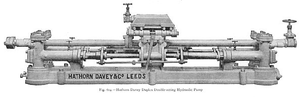 | Left: A Hathorn-Davey duplex double-acting pump : 1920ish.
|
Water-powered mine pumps persisted well into the 20th century, being definitely in use in the early 1930's.
THE LONDON HYDRAULIC COMPANY PUMP AT WAPPING
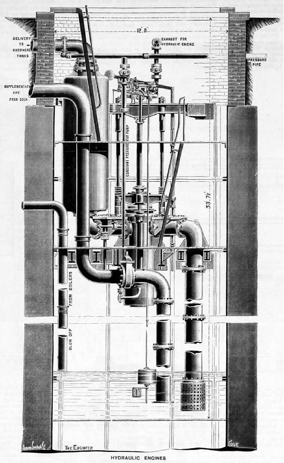 | Left: Water-powered water pump at Wapping: 1893
|
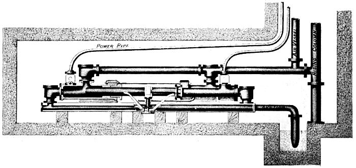 | Left: Elevation of Moore's hydraulic pump: 1900.
|
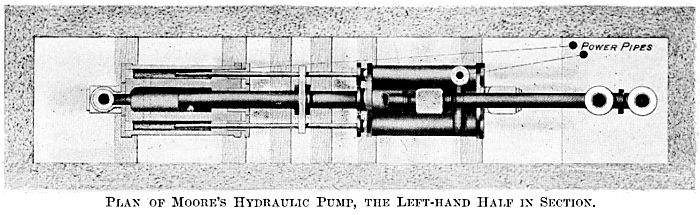 | Left: Plan of Moore's hydraulic pump: 1900.
|
The Moore company still exists, or at least it appears to; the name may be coincidence. See www.moorepump.com
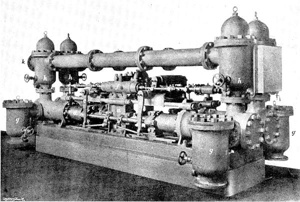 | Left: A Kaselowsky duplex double-acting pump : 1900.
|
This table gives some details of Kaselowsky installations in Westphalia, Germany, in 1900:
| Name of colliery | Pump depth | Water pumped |
| . | Feet | gallons/minute |
| Pluto | 1656 | 550 |
| Pluto | 2033 | 550 |
| König Wilhelm | 1541 | 880 |
| Monopol | 2542 | 440 |
| Gottessegen | 984 | 1100 |
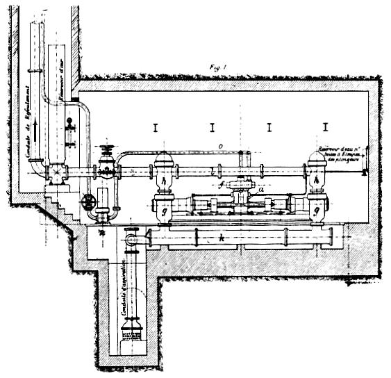
 | Left: Plan view of a Kaselowsky pump installed underground: 1900.
d Pump plungers g Suction-valve chambers h Discharge-valve chambers |
Kaselowsky pumps were also installed outside Germany; see this link: whc.unesco.org/en/tentativelists/5139
...which describes a coal mine near Seville, Spain. I quote:
"Special mention should be made of the remains at shaft No 5 which include the metallic extraction crane powered by the Bollinclx (1922) steam engine, the engine house, sieves and washing tanks, a Babcok Wilcox boiler, Kaselowsky drainage pump house, Schlamms tanks (coal sludge decantation reservoirs) and the electical power plant (1926). Shaft No 7 features the water tower (1928), the crane and engine house (1926-28), energy distribution tower (1929), electrical power plant and workshop buildings."
 | Left: End elevation of a Kaselowsky pump installed underground: 1900.
h Discharge-valve chambers k Suction pipe w Pump well x Conduit to rest of mine y Sluice valve for shutting off conduit |
 | Left: Side elevation of a Kaselowsky pump installed underground: 1900.
g Suction-valve chambers h Discharge-valve chambers k Suction pipe |

|