Gallery opened: Dec 2006
Updated: 2 Dec 2025
Little Giant Water motor updated here.
 
| |
A water motor, as opposed to a positive-displacement water engine, was a small Pelton-type water turbine, often driven from a domestic tap; these were used for many light tasks, such as driving centrifuges and stirrers in chemical laboratories or running sewing machines. Like water engines, they were eventually displaced by electric motors.
There is nothing particularly unusual about a Pelton turbine, but their use for providing small amounts of domestic power seems to be virtually forgotten. Hence this gallery of the museum. Within each section the exhibits are in as close to chronologival order as I can get.

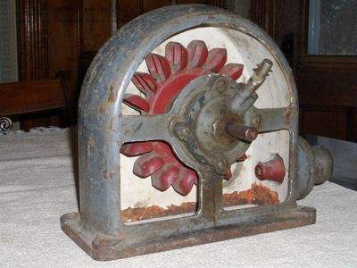 |
| Left: A typical water motor
The most usual form of water motor was a vertical Pelton wheel like this one, where one side has been cut away. Water shoots out of the jet on the lower right and strikes the buckets on the wheel, making it rotate. The used water then falls out of the bottom of the casing in this model
The purpose of the pipe angling upwards from the shaft bearing is unknown, but it is probably some form of lubricator.
This type of machine may look a little crude, but it has a high energy conversion efficiency, usually over 90%.
Image copyright by Robert Barrett
|
WATER MOTORS IN THE HOME
 |
| Left: A Lane water motor coupled to a sewing machine: 1881
It looks like the Pelton wheel is horizontal, which was unusual. There seems to be some sort of reduction gear (probably a worm and pinion) driving the small shaft with the pulley at the end. The treadle appears to be controlling operation, presumably by actuating an inlet valve. Unfortunately the original picture is not very clear.
Note the two hoses for water inlet and outlet.
From Knight's American Mechanical Dictionary 1881.
|
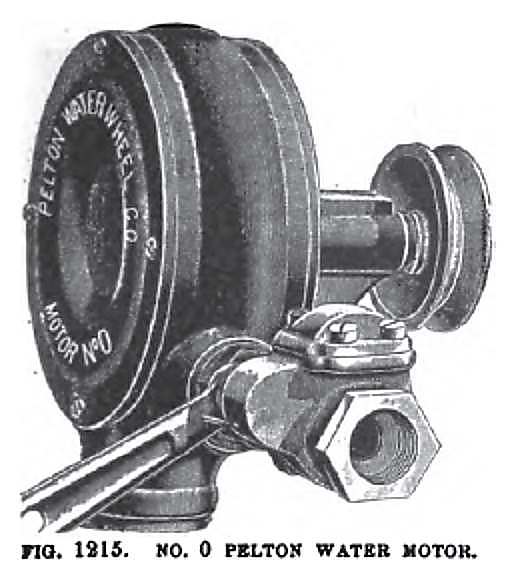 |
| Left: American Pelton wheel water motor: 1895
Water entry is at the side, controlled by a valve whose handle can be seen at lower left. The exhaust is the large pipe at the bottom.
From catalogue issued by Chas A Strelinger & Co, of Detroit, Mich; 1895
|
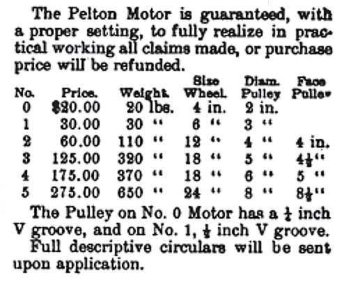 |
| Left: Specifications of Pelton wheel water motors: 1895
This table refers to a range of Pelton motors that starts with the smallest, Number 0 illustrated above.
Given the apparent confidence of the company in its products, it is a little curious that no figures are given for power, speed, or water consumption.
From catalogue issued by Chas A Strelinger & Co, of Detroit, Mich; 1895
|
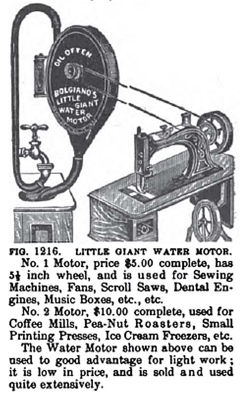 |
| Left: The Bolgiano Little Giant water motor: 1895
This motor, apparently hinged to the wall, looks like it is quite large; taking the scale from the sewing machine it must be something like two feet across. On the other hand the text claims that a 5-1/2 inch wheel will drive a sewing machine. One wonders if the drive pulley really was off-centre in the casing; if it was, the idea was probably to give free escape for the exhaust water.
Regrettably the drive belt has just snapped in two places simultaneously, so no sewing will be done for the time being.
Picture from catalogue issued by Chas A Strelinger & Co, of Detroit, Mich; 1895
Here are a couple of random adverts for the Bolgiano:
TERRITORIAL RIGHTS: THE wonderful Bolgiano water motor: fits any smooth faucet and operates all kinds of light machinery without cost for power; Midwinter Fair privilege for sale: a wonderful invention, promts* lug (sic) big returns. Pacific Coast agents. NORTON BROS. CO., 218 N. Main St. Room 13. Los Angeles.
From San Francisco Call, Volume 75, Number 72, 10 February 1894
BOLGIANO'S LITTLE GIANT WATER MOTOR, the nicest Christmas present that can be had. the wonder of the age, for sale by A B SLAY, MAKER. Sole Agent. Alexandria. Va.
From Alexandria Gazette, Volume 95, Number 36, 10 February 1894. This suggests that A B Slay did the manufacturing; they are unknown to Google.
|
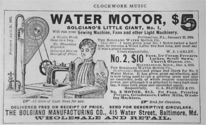 |
| Left: The Bolgiano Little Giant water motor
Here it is driving a sewing machine. The lady does not look impressed.
John Bolgiano took out two US patents relating to water motors:
US 496,182 A Water-motor. Publication date 25 Apr 1893. Inventors: John Bolgiano
US 519,521 A Faucet attachment. Publication date 8 May 1894. Filing date 4 Aug 1893. Inventors: John Bolgiano
John Bolgiano is unknown to Google apart from his patents and this website.
A very appropriate business address. 415 Water Street.
Source: the book Clockwork Music by Arthur Ord-Hulme. Pub: George Allen & Unwin, 1973
|
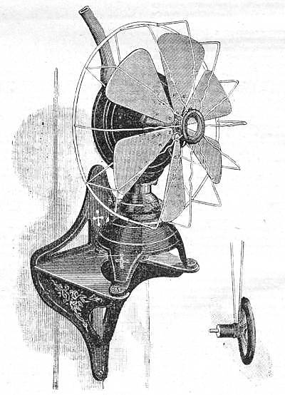 |
| Left: A fan powered by a water motor: 1898
The water is supplied through the hose at the top. The fan can be swivelled on a ball joint at its base. It looks as though the exhaust water falls out through the middle of this ball-joint, but the original article makes no mention of how this is handled.
"By attaching a balance-wheel and pulley, the motor can be made to drive a ceiling or post-fan, or a sewing machine, with water working at a pressure of 40psi. With a pressure of 50 to 60 psi, a telephone exchange generator can be driven... The motor consumes about 7 pints of water per minute."
This fan was manufactured by the A Rosenberg Company of Baltimore, Md, USA.
From English Mechanic 9 Sept 1898, p83; originally from Scientific American
|
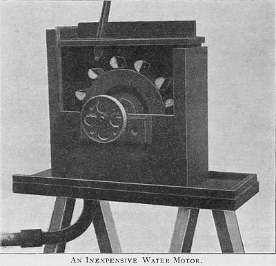 |
| Left: A home-made water motor, by a certain Mr F M Jephcott: 1904
The jet of water can be seen coming in from the top. The drum was 7 inches in diameter by 1.25 inches wide. The buckets were made from tin and fastened on with wood-screws. Mr Jephcott reported he got the water supply through 0.5 inch pipe from a main with a 70 foot head, and this gave enough power to run a small dynamo.
From Model Engineer and Electrician, 2 Jan 1904.
|
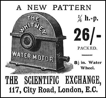 |
| Left: The Whitney water motor: 1906
This is a typical water motor. The water supply is connected to the horizontal spigot at lower right, and the waste water drops out of the bottom of the casing. The Pelton wheel inside is directly connected to the pulley on the side.
So just how much power could you expect from a water motor? In a report in Model Engineer & Electrician for 2 Feb, 1905, it was stated that Messrs Whitney of 117 City Rd, London, were selling a water motor with an 8.5 in diameter wheel rated at 1/4 hp with water pressure of 60 psi. This was considered to be conservative as "a 5in wheel would normally be so rated".
Picture from Model Engineer and Electrician July 5, 1906
|
Some more performance data was gleaned from a catalogue produced by Gilkes of Kendal, who also made big industrial turbines. This table refers to their Number 3 water motor, which had an overall height of 17in:
Water
PressurePowerSpeed
psiHPrpm
401/7625
601/3725
901/2850
| | | | | | | | | | | | | | |
And how much did they cost? This advert appeared in the for sale section of The Model Engineer & Electrician for October 25, 1906:
"Water Motor, 9ins diameter, brass wheel, all brass fittings; 14s,; bargains.- Hinchcliffe, 3 Castlegate, Huddersfield."
Considering that the Whitney motor above cost 26s, it does indeed appear to be a bargain.
The Model Engineer and Electrician, 15 Feb 1912, carried this ad:
Water Motors:
The "Midget" 6s 9d; castings 3s 6d. The "Amateur" 1/8 hp, 18s 9d; castings 6s 6d. The "Whitney" 1/4 hp, 26s; castings 18s 6d. The most inexpensive means of obtaining power for all purposes.
The reference to castings needs explaining. In those days you could buy just buy the castings for steam engines etc, and do all the rest of the construction yourself.
By 1927 the cost of the Whitney motor had gone up to 45s, or 25s for just the castings.
 |
| Left: A design for a water motor: 1906
The jet of water comes in from the bottom right. The function of the 'splasher plate' is currently obscure.
This design was published in a series of articles called "Water Motors and other Hydraulic Machines" by a Mister Joseph G Solis.
From Model Engineer and Electrician, 30 Aug 1906.
|
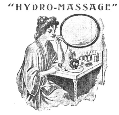 |
| Left: The Warner Motor Company's 'Hydro-Massage' machine: 1906
This water-powered massage machine is not quite what it seems. It was not for massaging the tip of your nose, as shown here. It is a hydraulic vibrator.
An advert taken out by the Warner Motor Company Inc. (New York) in Modern Women. They had offices in the famous Flatiron building.
Bibliography: The Technology of Orgasm, by Rachel Maines. Pub John Hopkins 1999.
|
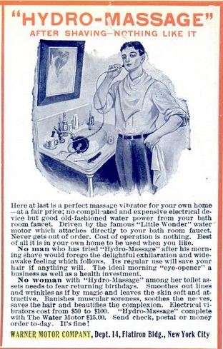 |
| Left: The Warner Motor Company's 'Hydro-Massage' machine: 1906
I think we can all agree that after shaving there's nothing like a thoroughly good session with a vibrator. The advert assures us that for women at least, it 'soothes the nerves'. Verb sap.
Note that the blurb refers to 'good old-fashioned water power', intended to fend off the 'electrical vibrators' mentioned further on in the ad text.
From Popular Mechanics Dec 1906
|
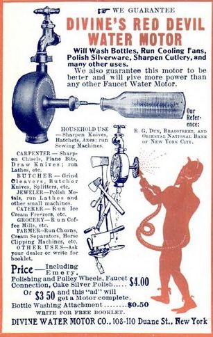 |
| Left: The Red Devil water motor: 1906
This looks very similiar to the Warner advert above, but is actually from a completely different company.
The name of the company (which does not exactly sit well the name of the motor) suggests that it would run best on holy water, but I imagine this was not the case; certainly it appears that Old Nick has no objection to sharpening the end of his tail with it.
From Popular Mechanics Dec 1906
|
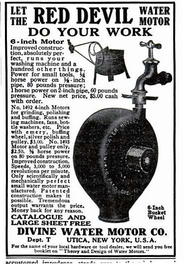 |
| Left: The Red Devil water motor: 1912
There's not much to say about this water motor that is not written in the advertisment.
From Popular Mechanics Jan 1912
|
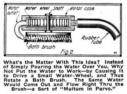 |
| Left: The water-powered brush- a suggestion for an invention: 1920
This is an ingenious idea- put the water to work twice. However, I was prepared to find out the idea had vanished without trace; I was wrong. There are indeed turbine driven brushes available today. See
here, for example. And there's this which very clearly uses a Pelton wheel with a worm reduction drive to the brushes.
What's the Matter With This Idea? Well, Pelton wheels go round at high speed if they are to work at all efficiently, so with no reduction gearing that brush is going to be going round at one hell of rate. Sounds like it could be hard on the skin...
Otis A Pope was granted US patent 1,817,644A in 1931 for triple brushes on an axle, powered by two Pelton wheels without any gearing.
Image from Electrical Experimenter May 1920
|
 |
| Left: The Winter water motor design: 1921
The design was intended for home construction. Here the jet of water points downwards.
A motor to this design was used to drive a washing-machine. Interestingly the article describing it was (allegedly) written by the constructor's wife.
Source: The Boy Mechanic, Book 1. 1921. The book seems to have been published by the Popular Mechanics Co.
|
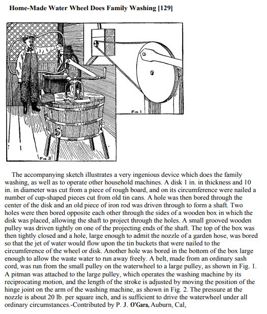 |
| Left: Water motor doing the laundry: 1921
This is a separate article from the Winter one above.
Note: a 'pitman' is what would be called a connecting-rod on a locomotive.
Source: The Boy Mechanic, Book 1. 1921.
|
 |
| Left: This is a rare picture of a water motor doing a job of work.
The motor is geared down by what appears to be about 8 times, to rock a developing tray for photographic plates. The exhaust water is then ingeniously used for washing the developed plates.
From Things To Make by Archibald Williams.
|
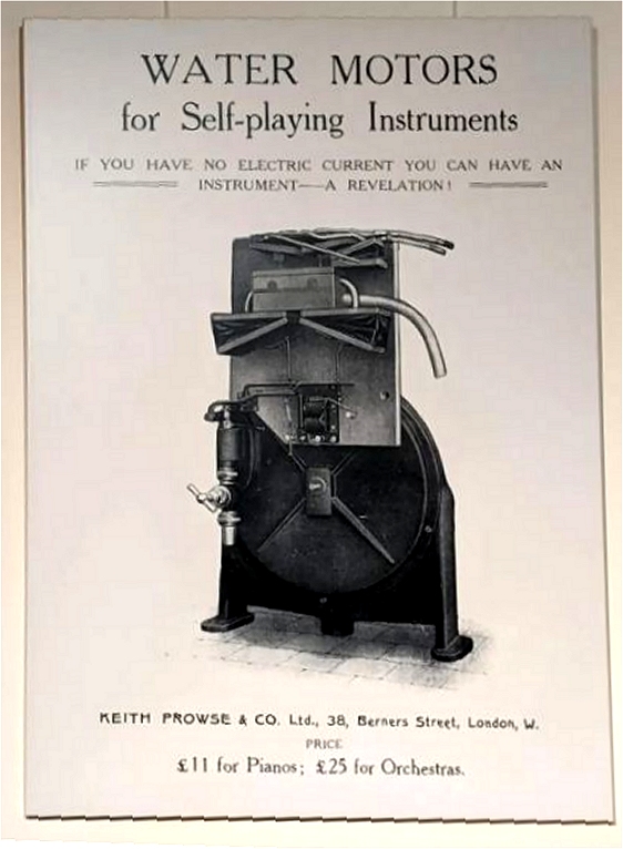 |
| Left: Water motor for driving self-playing instruments: date unknown
This machine was designed to power a pianola or player piano. The Museum Staff have now found an image of better quality. You can see what is clearly a Pelton-wheel motor driving two bellows by some sort of crank arrangement. Presumably the wheel was much geared down. The thing above the wheel axle may be some sort of speed governor.
The rectangular box at the top is some sort of air reservoir, fed by the two bellows, and with a hose leading away to the instrument. There are smaller pipes at the top, of unknown function, and a third small bellows which may be for pressure regulation.
The water inlet, with valve, is at the left of the wheel; the size of the handle suggests that the machine was about 3 feet tall. There appears to be a water outlet at the bottom of the wheel.
The Keith_Prowse company still exists but now deals in leisure and hospitality.
|
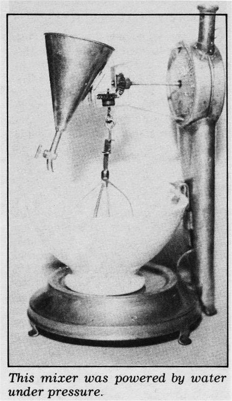 |
| Left: Food whisk powered by water motor: date unknown
This picture comes from the book mentioned below; there was no information as to its original source. It looks rather crude- note the unguarded bevel gears; these look like 1:1 so there was no gearing down and the (presumed) Pelton wheel in the box would have been working inefficiently.
I believe that this setup is specifically designed to make mayonnaise. You make it by putting egg yolks and mustard in a bowl and adding olive oil drop by drop, whisking constantly. It is a very labourious cooking process, and a powered whisk is an excellent idea. The funnel to the left holds the oil while the tap allows a suitable dropping rate. There is a reference to making mayonnaise with water power below, but I have been unable to find any other reference. This seems odd as it seems like an ideal application for a modest amount of water power.
From The World Almanac Book of Inventions by Valerie-Ann Giscard d'Estaing, published 1985. Yes, Val�rie-Anne Giscard d'Estaing is the eldest daughter of once-President of the French Republic, Val�ry Giscard d'Estaing.
|
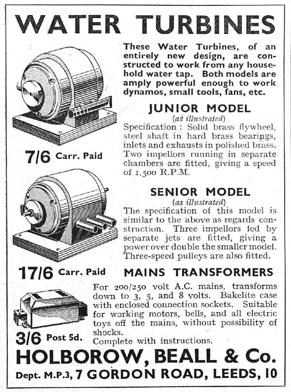 |
| Left: Water motors: 1937
This is the most recent advert for water motors as such that I have found so far.
By 1937 many houses in Great Britain were connected to an electricity supply, (The only figure I can find is that 9 million users had been connected by 1938) and the market must have been shrinking fast. Interestingly, they are described as "water turbines" rather than "water motors", perhaps because it sounded more up-to-date.
These motors have twin and triple turbine wheels, clearly of the Pelton kind; the advantage of this over a single bigger wheel is unclear. Probably it simply made for a more compact motor. The nozzles are visible on this side, and it is presumably the exhaust pipe or pipes that can just be seen sticking out of the far side of each motor.
The ad for a mains transformer at the bottom of the page is a sign of the times.
From Practical Mechanics Jan 1937, p237
|
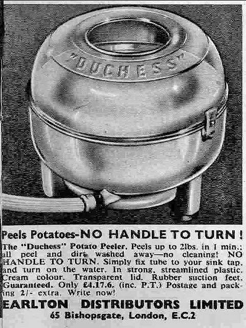 |
| Left: The Duchess potato peeler: early 1960s
Here is a relatively recent application of a water motor.
The Duchess potato peeler sat in the sink, with the hose connected to the cold tap. Inside was a crude Pelton turbine on a vertical axis, driving a horizontal plastic plate which had an abrasive moulded surface; as did the inside of the bowl. The plate spun at enormous speed; the outflow from the Pelton came up through the annular gap, washed the abrasive and the potatoes, and flowed away back down the gap and into the sink. It was very effective: the peelings went down the drain as a fine slurry, as did much of the potato...
Thanks to John Flindall for bringing this to my attention.
|
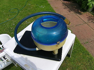 |
| Left: The Duchess potato peeler: early 1960s
Here is the real thing.
No doubt ideal for making Duchess potatoes.
Thanks to John Flindall for providing the colour image.
|
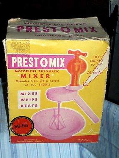 |
| Left: Prestomix food mixer: early 1960s ??
This ingenious device is apparently supported solely by its attachment to the tap; the white collar screws onto it. Not much use if you didn't have a threaded tap. However, it will work at 100 speeds! In reality it would no doubt work at an infinite number of speeds, depending on tap adjustment. The date is a guess, partly based on the price of $6.95.
You may be wondering what the point is, as electricity supplies were widespread in the USA by then. I imagine cost is the issue; it would be much cheaper to make than a mixer with an electric motor.
The manufacturer was probably National Presto Industries Inc, of Wisconsin, assuming this is another of their products. They appear to be still in business.
Image copyright by Robert Barrett
|
WATER MOTORS DRIVING DYNAMOS
 |
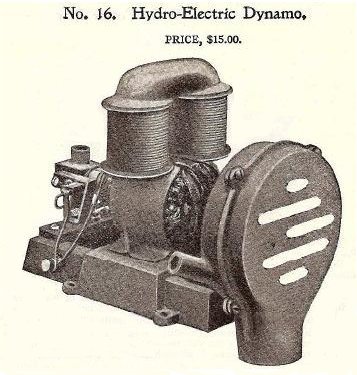
| Left: Water motor and dynamo combination: 1912
In the early days of electricity, you had to make it yourself, with primary cells or a dynamo driven in some way. Water motors were used to drive small dynamos; they wre beautifully simle compared with steam or IC engines but the output was limited.
This outfit was intended for charging accumulators that were then used to run a radio.
Given the open construction of the dynamo, there is a big incentive to get all the pipes truly water-tight. However, if the dynamo was for charging filament batteries (HT batteries were usually of the dry-cell type) the voltage would have been low and there would have been little risk of electric shock.
|
 |
| Left: Water motor and dynamo combination: date unknown
|
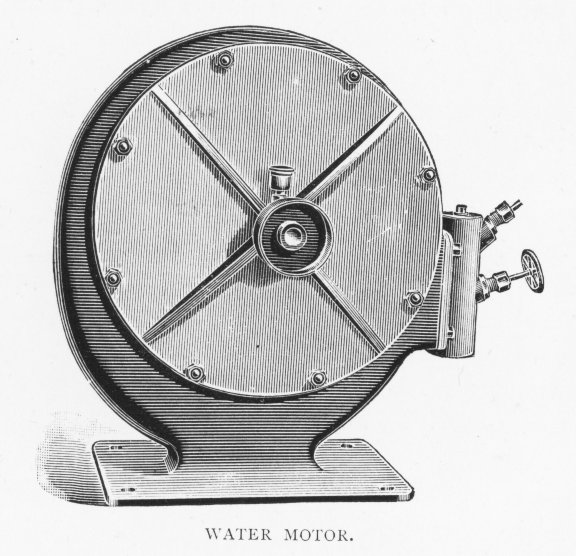 |
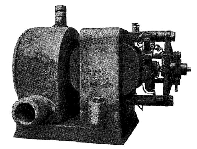
| Left: Water motor for driving dynamo: 1898
This picture comes from Electricity in Town & Country Houses by Percy E Scrutton, pub 1898 by Archibald Constable.
No reference is made to it in the text, but it was presumably considered suitable for driving dynamos or it wouldn't be in the book.
it is difficult to judge the size of this thing, but given the size of the handwheel at extreme right, I would guess at a diameter of about 30 inches, making it one of the larger water motors in this gallery. Exhaust was presumably through the base.
|
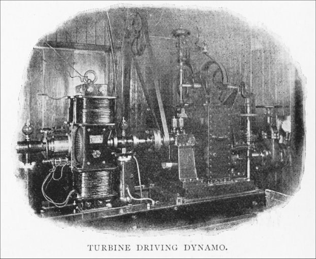 |
| Left: Water motor and dynamo combination: 1898
This is a hefty watermotor-dynamo installation. Once again it is not easy to estimate the scale, but from the general look of it I think the box at the right which contains the turbine is about two feet high. Note there is what looks like a 6-inch pipe coming in at the extreme right.
At top centre there is a small ball governor.
This picture also comes from Electricity in Town & Country Houses by Percy E Scrutton.
|
 |
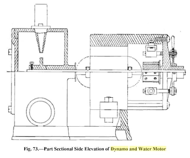
| Left: Water motor and dynamo combination: 1920-1943
This picture comes from Small Dynamos And How To Make Them - Practical Instruction On Building A Variety of Machines Including Electric Motors by 'various authors'. The book is freely available on the Internet but the publishing date is given as 2009, which is much too recent compared with the style of the book- it is probably the date a physical copy was scanned. Further research shows that three editions were published between 1920 and 1943. The authors remain unknown.
It is claimed that it gives 8 Volts at 2 Amps with a 50 psi water pressure, and a 4-Volt accumulator can be charged with only 35 psi. Water entry is at top left and exhaust via the larger pipe at bottom left.
The importance of accumulator charging was considerable. Radios were in extensive use before mains electricity became widespread, and the valve filaments were powered from lead-acid accumulators. If you did not have one of these handy devices to recharge them, you had to carry them to the local radio dealer who would have some form of generator, probably driven by a gas-engine. The high-tension, which required much less current, was usually provided by dry batteries.
|
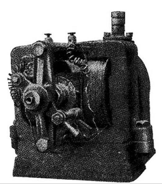 |
| Left: Water motor and dynamo combination: date unknown
Another picture from the dynamo end.
This picture comes from Small Dynamos And How To Make Them - Practical Instruction On Building A Variety of Machines Including Electric Motors by 'various authors'.
|
 |
| Left: Water motor and dynamo combination: date unknown
This shows the inside of the water motor, with the jet nozzle at the top. No turbine buckets are visible, and the thing projecting into the interior is drawn as part of the casing so it's not going to go round; looks like a drawing mistake.
This picture comes from Small Dynamos And How To Make Them - Practical Instruction On Building A Variety of Machines Including Electric Motors by 'various authors'.
|
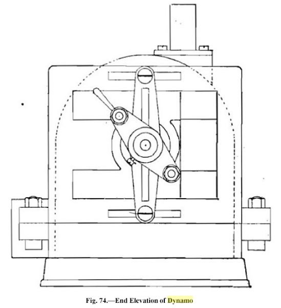 |
| Left: Water motor and dynamo combination: date unknown
This drawing frankly adds little to our knowledge. Some dimensions would have been nice.
This picture comes from Small Dynamos And How To Make Them - Practical Instruction On Building A Variety of Machines Including Electric Motors by 'various authors'.
|
 |
|  |
| 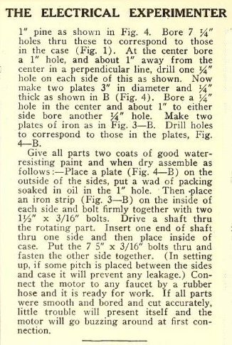 |
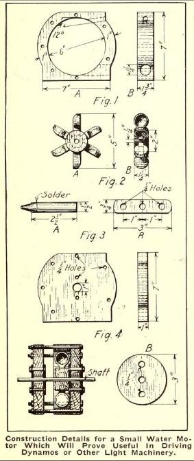
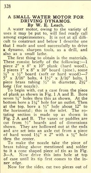
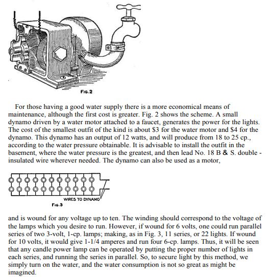
| Left: Water motor for driving a dynamo: 1917
This article gives constructional details for a water motor for driving a dynamo, etc. There seems to be nothing special that makes it especially suitable for dynamo work.
The article comes from The Electrical Experimenter for September 1917. The very next article encouraged amateurs to experiment with X-ray tubes. Not a good idea.
|
 |
| Left: Water motor and dynamo combination: Boy Mechanic #1
Source: The Boy Mechanic, Book 1, 1921.
|
WATER MOTORS FOR MECCANO
The Meccano construction system incudes a comprehensive range of chains, cranks, and gears and the desirability of powering models was recognised very early on. Official Meccano motors have worked by clockwork, electricity and even steam, but I have only just been made aware of the Meccano water motors.
 | | 
|
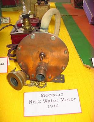
Above: Meccano water motor No 2: 1914
The water inlet is at the top, and the outlet at the bottom in the right-hand picture. One of these changed hands for no less than �1,927 on Ebay in June 2011; they are considered very rare. Note there is an output shaft on both sides of the casing. This water motor was introduced in 1914.
|  |
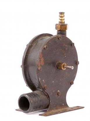
| Left: Meccano water motor No 2: 1914
This No 2 motor has the original inlet hose and tap connector.
This image was sent to me by one of my many correspondents and I have been unable to establish its provenance. If you feel I have violated any copyright please let me know.
|
 |
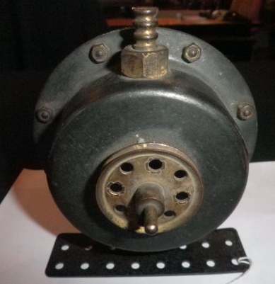
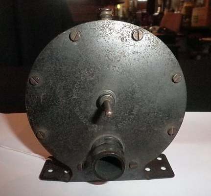
| Left: Meccano water motor, model number unknown: 1914
This is also a Meccano water motor, though different from the No 2 shown above; its model number is not currently known. Since the motor shown above is No 2, this might be No 1. This is supported by the fact that it looks a bit cruder in construction, with two screwed endplates rather than the dished body and single endplate of the No 2 motor.
The height is 5 inches to the top of the water inlet.
Note the large exhaust pipe at bottom left. Water does not of course expand when run through a turbine (unlike steam) but several manufacturers issued stern warnings that efficency would be much compromised if the water could not get away freely.
|
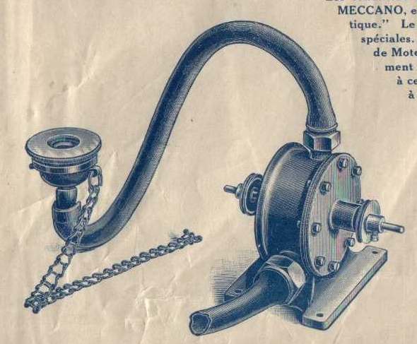 |
| Left: Meccano water motor: 1914
This superb illustration is from a French instruction manual of 1914 or 1915. It appears to show the motor illustrated just above, and not the No 2 motor, though the base is different, without "Meccano-spaced" fixing holes. The power output was stated as 1/60 of a horsepower with a water head of 21 metres. (69 feet) The price of the water motor was 17 Francs, while the electric motor on the previous page was a lot more expensive at 75 Francs.
The hose, tap connection, and chain look identical to that of the No 2 motor above.
|
My first Meccano models were driven first by a hand-crank, then by the tiny Magic clockwork motor which was sorely lacking in torque. I progressed to the rather more effective No 1 clockwork motor with the reversing lever, and then the E15R electric motor, which was when things really got moving. I then bought one of those little red Emebo motors, (can't remember why...) and finished up with two Powerdrive motors (the one with the cylindrical 6-speed gearbox) which I used in some robotics experiments. I still have all of them.
WATER MOTORS IN THE LABORATORY
Before mains electricity was widely available, water motors were a good source of small amounts of power in chemical laboratories. Steam power required constant skilled attendance and there was always the possibility of a boiler explosion. Hot air engines were safe, but still required stoking and the storage of fuel.
In 1882 Henry A Rowland was making diffraction gratings in Baltimore with a machine that scribed parallel lines on glass with a diamond point. This machine, which was basically a large crank and sliding arm, had to be driven as uniformily as possible to get good-quality gratings. "The overall power for the ruling engine came from a water-motor, via a large pulley." is all that is said in The Command of Light, by George Sweetman (American Philosophical Society, 2000) which is an account of Rowland's career. A diagram in the book makes it clear that the motor was geared down to drive the ruling engine, which makes it plausible it was a relatively high-speed water-motor rather than a piston-based water engine. The water motor appears to have been mounted on a higher level than the ruling emgine.
The water motor was fed from a header tank at a height, to give a constant torque.
"The motive power of the machine is a hydraulic engine. The water is kept at a constant height in a tank near the roof, to insure unvarying speed." from Sketch Of Henry Augustus Rowland By Charles Edward Lloyd in Popular Science Monthly Volume 49 May 1896.
Whether this tank was fed from the city mains or water was pumped by a steam engine is not currently known.
I think this may be a unique application for a water motor
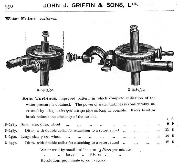 |
| Left: Water motors in the Griffin catalogue
This illustration is from a hefty catalogue called "Griffin's Chemical Handicraft" that runs to 850 pages; regrettably it is not dated, but Griffin did have a telephone number at the time. John Griffin and Sons ran a well-known laboratory supply firm in Kingsway, London.
These motors are described as "Rabe turbines", though as far as can be deduced from the illustrations they were a form of Pelton wheel. The phrase "Rabe turbine" seems to have specifically referred to small turbines for laboratory work, for example: here. (see page 243)
Frederick William Rabe (Jr) appears to have been a turbine expert at Yale University. An article by Rabe, "A turbine for laboratory purposes" appeared in The Journal of the Chemical Society (Great Britain) in 1888.
|
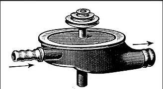 |
| Left: A Rabe turbine
Google renders the German description as "For connection to the water pipe, aluminum wheel, creating a quiet and smooth movement is achieved."
|
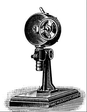 |
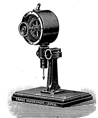
| Left: A development of the Rabe turbine in a laboratory apparatus catalogue
This version has integral reduction gearing, but it is not known what, if any, changes were made to the basic Pelton construction.
Google renders the German catalogue description as "Turbine, new construction, is characterized by large velocity and thereby significantly greater force performance over the Rabe turbine." The last bit came out originally as "the raven's turbine." because "Rabeschen" means "belonging to the raven".
From the catalogue of Franz Hugershoff of Liepzig 1911.
"Illustrierte Preisliste III �ber Biologische Apparate" (p0026, Fig b270c_d_e)
|
 |
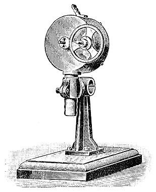
| Left: Rabe turbine as above, with cover removed.
The slanting spigot at the top is the water inlet. The exhaust exits downwards.
From the catalogue of Franz Hugershoff of Liepzig 1911.
"Illustrierte Preisliste III �ber Biologische Apparate" (p0026, Fig b270a_b_e)
|
 |
| Left: A Rabe turbine
Google renders the German description as "Water motor (turbine) Rabe, for connection to water mains, with gear ratio for low speed, with greater force development. (20 cm diameter)"
I think this is the same motor again, clearly being manufactured and then sold to laboratory apparatus distributors.
From: E Zimmermann, 1912. "Psychologische und Physiologische Apparate. Liste 25." (p0235, Fig 4527_30)
|
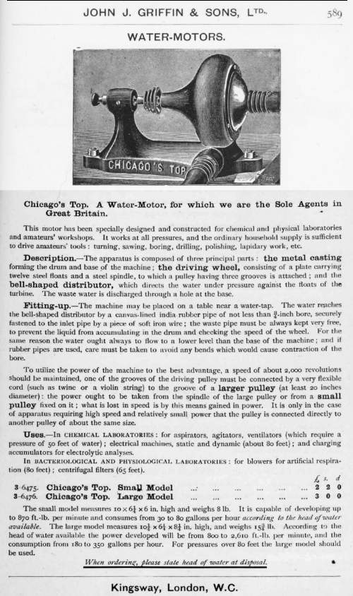 |
| Left: The Chicago's-Top water motor in the Griffin catalogue
This device is a bit of a mystery. Almost all the water motors on this page are very clearly of the Pelton-wheel type, but this is described as having a driving wheel carrying "twelve steel floats" rather than buckets, (though floats might mean buckets, I suppose) and having a "bell-shaped distributor" rather than the usual Pelton nozzle.
The motor is unknown to Google.
|
Another excellent source of information on water motors in the laboratory is the "Catalogue of General & Industrial Laboratory Apparatus", issued by Chas Hearson & Co Ltd, of Willow Walk, Bermondsey, London in Jan 1930.
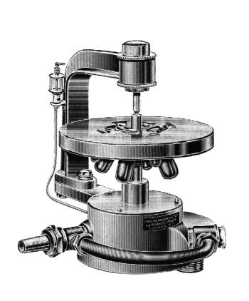 |
| Left: A water motor powered centrifuge: 1930
This water motor has twin nozzles for greater power output. The water exhaust is taken out at lower right, either downwards or sideways by using the appropriate hole. The small glass cylinder at upper left is presumably a lubricator for the lower bearing, which would have borne the weight of the turbine wheel and the test-tube carrier.
These motors were capable of respectable speeds, given enough water pressure; this table was provided by Hearson & Co:
psirpm
101125
201875
302625
403375
504125
604875
705625
| | | | | | | | | | | | | | | |
No figures were given for power output.
From the Chas Hearson catalogue.
|
 |
| Left: A water motor powered centrifuge: horizontal section. (looking from top) 1930
The water exhaust is on the right. This part of the drawing is distorted as it was right in the fold of the book; the exit pipe was really circular in cross-section.
Quite why the second nozzle was set at an angle is unclear; 180 degrees seems to be the obvious alignment as it would minimise side-force on the bearings. I should have thought the exhaust could have been offset without any problems.
From the Chas Hearson catalogue.
|
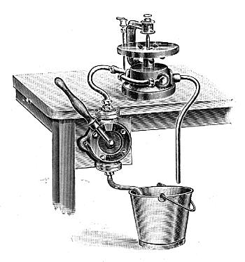 |
| Left: The water motor powered centrifuge worked by hand-pump: 1930
Setup for use where there is no piped water supply; the water exhaust here is taken out from the side and returned to the bucket. The Hearson catalogue has a fine old colonial flavour, many of its products being aimed at organisations in farway places where neither mains water or electricity was available. With this arrangement, unskilled local labour could be put to work on the pump handle.
On further thought, I'm not sure that this makes a huge amount of sense. Surely it would have been easier to drive the centrifuge directly from a handle, geared up by a suitable amount? This would eliminate losses in the pump, pipework, and turbine.
From the Chas Hearson catalogue.
|
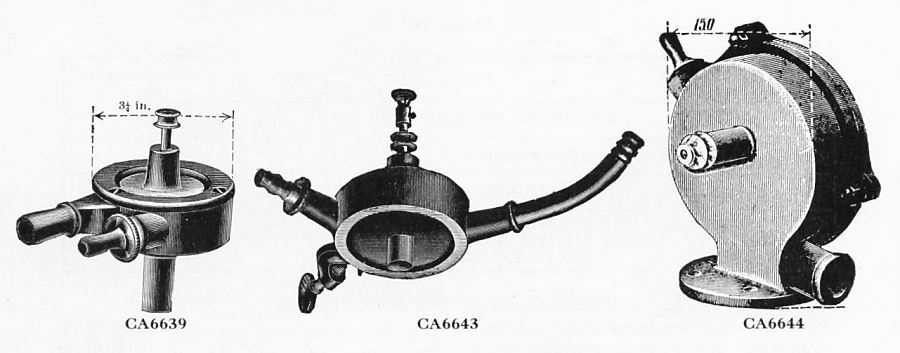 |
| Left: Water motors in the Townson & Mercer catalogue: 1937
CA6639 had a water wheel 2.5 inches in diameter, turning at 2500 to 4000 rpm, depending on the water pressure available; it cost �1 1s. A variation on this, CA6641 had a 2.75in wheel to give greater power.(And greater water consumption) and cost �1 7s 6d. CA6642 was top of the power range with a 3.75in wheel; it cost �1 15s.
Townson & Mercer of London EC3 were suppliers of laboratory equipment. They always refer to their water motors as 'turbines'.
|
CA6643 is a different motor with a 75mm wheel and a boss head attached so it could be clamped to a laboratory stand; it cost �1 17s 6d. Note clamp on shaft at top for holding a stirrer.
CA6644 is a vertical motor with a 2.75in diameter wheel. Water inlet is at top left and water exhaust at lower right. Cost �1 10s.
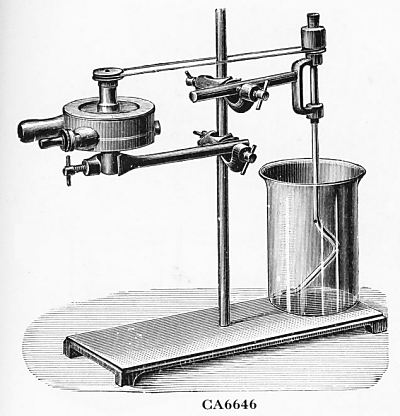 |
| Left: Typical laboratory application for a water motor: 1937
Item CA6646 was a complete stirring assembly; it cost �2 4s 0d, including a 1000 cc beaker.
From Townson & Mercer catalogue 1937. I am glad to report that Townson & Mercer still exist today.
|
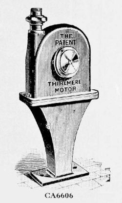 |
| Left: Thirlmere water motors: 1937
Item CA6606 was the smallest Thirlmere motor sold by Townson & Mercer; it cost �2 0s 0d. It was described as Size 000. The range went up to Size 3, with an output of 1.7 horsepower at 600 rpm; an 80 psi water supply was required to attain this, and 40 gallons a minute were used.
The water presumably exhausts downward through a hollow pillar. The range of motors was described as being fitted with gunmetal wheels and bearings. The nozzles were of gunmetal ("and not lead", the description insisted) and the casing was of cast iron.
Thirlmere motors were manufactured by W H Bailey; there are more details on this company in the next section.
From Townson & Mercer catalogue 1937.
|
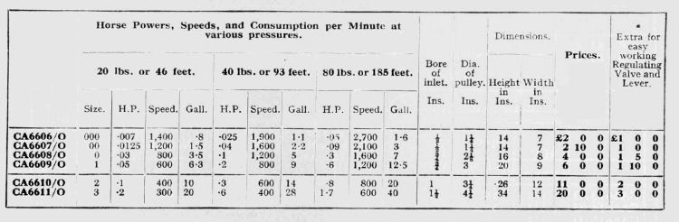 |
| Left: Thirlmere water motors: 1937
This table gives a useful overview of what the Thirlmere water motors could do. You need the biggest size and a water supply at 80 psi to generate 1.7 horsepower, using 40 gallons a minute.
From Townson & Mercer catalogue 1937.
|
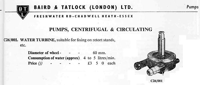 |
| Left: Water turbine from the Baird and Tatlock catalogue: 1954
This is the only water motor in the 1954 catalogue; clearly they were falling out of fashion. No specs for power or rotational speed are given, possibly indicating this wasn't a product they were too concerned about.
Another well-known supplier of laboratory equipment was Baird and Tatlock, of Chadwell Heath, England.
Baird and Tatlock were founded in 1881. |
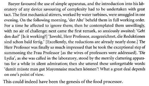 |
| Left: The introduction of water-powered stirrers
An anecdote about the introduction of water-powered stirrers into the laboratory of Adolf von Baeyer (1835-1917) one of the great German organic chemists.
The Frau Professor's comment means: "That should be able to make good mayonnaise".
From a review article by John Read in Nature, 131, 294, (1933)
|
WATER MOTORS IN INDUSTRY
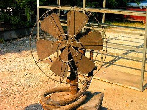 |
| Left: Water-powered industrial fan
There isn't much to give scale to this fan, but at a rough guess it is about 3 feet high. That would make it too large for domestic use, and I suspect it was intended to cool down workshops.
Date and location unknown.
|
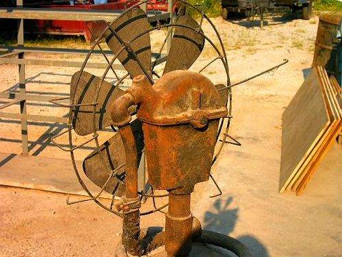 |
| Left: Water-powered industrial fan
The fan from the rear. The water that powers it enters through the hose at left, and the exhaust water falls down the hollow supporting column and exits from the T-junction near the base.
|
 |
| Left: A water motor in use today at Twyford water works, Hampshire
This water motor is of the usual Pelton type. It is used to dispense carbon to absorb residual impurities in the water.
The motor is the disc-shaped object at left, partly concealed by a pressure gauge. Operating pressure is 23 psi.
This explanation was given by the volunteer who provided the picture:
"The carbon plant in the corner of the mixing room was added when the diesel pumps were installed in the 1930's, to remove any possible contamination by diesel fuel. The plant is operated by a pelton wheel, driven by mains water pressure and it measured out a small quantity of carbon which the spent water from the pelton wheel washed through pipes, into the water softening tank. Here the carbon floated on the water and absorbed any oil present on the surface."
Image used by permission
|
 |
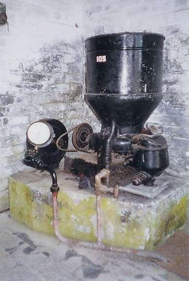
| Left: W H Bailey water motor: 1901?
This W H Bailey water motor was made at the Albion Works, at Salford, England. It ran a ventilation fan in a "killing shed" on Kuriheka Farm Estate, near Oamaru on the South Island of New Zealand, where animals were slaughtered for on-farm needs and the meat hung. The building dates from 1901 and the motor may well date from before then.
This motor is still in use. In the background a belt can be seen that runs upward to drive a large-diameter fan. The pink plastic is to stop the inlet pipe freezing in cold weather.
Graces Guide has a history of W H Bailey & Co. Water motors were only a small part of a very wide range of valves, pumps, etc. The company still existed in 1968 but it is nor clear if it is still around now.
Picture kindly supplied by Bruce Comfort.
|
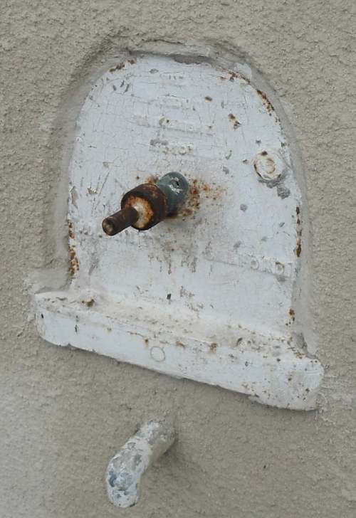 |
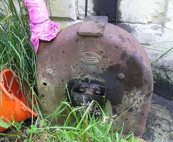
| Left: W H Bailey water motor: 1901?
This is another W H Bailey water motor, cemented into a wall in the basement kitchen of what was once the Empire Hotel in Oamaru. (see above) The pipe at the bottom is the water exhaust- no inlet is visible. It probably drove a ventilation fan or perhaps some kitchen appliance such as a mixer or a spit roaster.
Picture kindly supplied by Bruce Comfort.
|
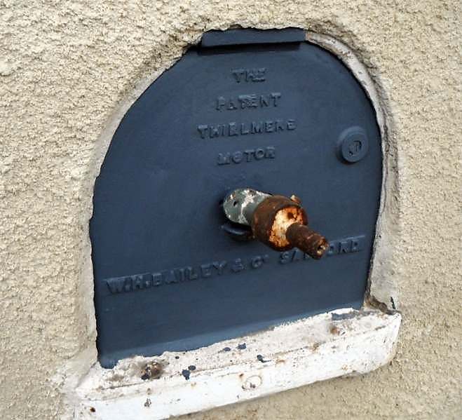 |
| Left: Thirlmere water motor by W H Bailey
This is the W H Bailey water motor shown above, after being cleaned up and painted, with name and maker now clearly visible.
Thirlmere is a water supply reservoir in the English Lake District, built in the early 1880's. It supplies Manchester via the Thirlmere Aqueduct. Baileys, as manufacturers of a large range of valves and pumps, probably had a major involvement in this project, and adopted the name for their water motor.
|
 |
| Left: A water motor powered fire alarm: 1949
British buildings protected by sprinkler systems always have outside alarm bells activated by small Pelton turbines. When the sprinklers begin to discharge onto a fire, the main flow of water lifts a valve that sends a small amount of water to the alarm turbine. This has the great merit that it does not rely on a supply of electricity to operate the gong. It is also immune from frost as the pipe to the alarm is kept empty of water until the system is activated.
A bypass valve allows the alarm to be periodically tested.
From Manual of Firemanship Part 4, p103. Her Majesty's Stationary Office, 1949
|
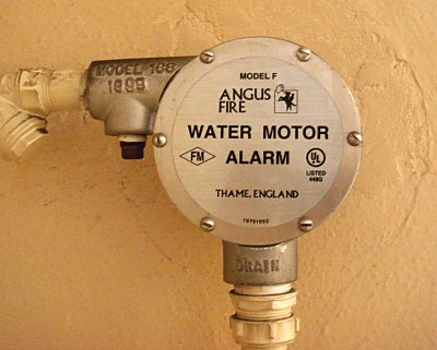 |
| Left: A water motor powered fire alarm: 2008
Alarm bells activated by small turbines are very much still with us. This picture was taken on the afternoon of the 5th of July, 2008, on the inside of one of the outside walls of the John Lewis department store, on Oxford St, London. Note the bottom pipe is marked "drain".
You can learn more on the Angus Fire website here (external link)
Authors photo.
|
You can buy a water motor from M & M Controls. I quote from their website:
"The Danfoss Nessie water motor program consists of the MAH, MVM and APM motors.
MAH motors for high-speed applications are based on the axial piston principle.
The MAH motor has a coated aluminimum housing with stainless internal parts.
The MVM-motor is a new low-speed high-torque water hydraulics motor designed according to the vane motor principle."
"The MAH and MVM motors vary in size from 4 cm3 to 12.5 cm3 per revolution (rated displacement).
The maximum operating torques vary from 8 Nm to 25 Nm and maximum outputs from 3 kW to 8 kW.
ON THE PELTON TURBINE
The Pelton impulse water turbine, on which most water motors were based, was invented by the American Lester Allan Pelton (1829-1908). He was born in Vermilion, Ohio in 1850 and moved to California during the gold rush. (1848-1855) Pelton worked there as a carpenter and millwright.
Water turbines and water wheels were not new, but Pelton's innovation was to shape the buckets on the wheel so that the impinging water was reversed in direction, thus extracting more energy from it. For greatest efficiency the buckets are receeding at half the speed of the water so that the water is brought to a stop.
The Pelton wheel was first used at the Mayflower Mine in Nevada City, California in 1878. By 1879 he had tested a prototype Pelton wheel at the University of California.
In 1887 a miner attached a Pelton wheel to a dynamo and thereby produced the first hydroelectric power in the Sierra Nevada Mountains.
A patent was granted to Pelton in 1889, and he later sold the rights to the Pelton Water Wheel Company of San Francisco.
The Pelton turbine works best with relatively small amounts of water at high pressure. It has a high energy conversion efficiency, usually over 90%.
LINKS
The water-motor lives on! See:
homepower.com
This describes a small Pelton turbine. See page 52.
More info on it: www.watermotor.net
Evans Engineering look like they know what they are about.
Water motors are often used to power irrigation equipment. See: www.kifco.com
A good site with many pictures (some of which seem to have been abstracted from here) is oldpelton.net. This covers watermotors up to the size where they are called 'pelton turbines' and live in huts.
Typing "water motor" into Google does not yield much. "Micro-hydro" however brings in a lot of info about modern small turbines.
