Gallery opened June 2012
Updated: 6 July 2017
More on Malone's engines


The Liquid Engines |
Gallery opened June 2012 |
This page was previously called The Malone Liquid Engine. Now it has become clear that Malone was not the only worker in the field, it has been renamed.
Virtually all prime-mover engines work with gases (such as hot-air engines) or gas and liquid. (such as steam engines) There have also been solid-expansion engines based on the expansion of solid material. But in one unique case, liquid alone was used; the expansion of water when heated under high pressure was used to drive a piston.
 | Left: Thuemmler's liquid engine: 1880
|
 | Left: Thuemmler's liquid engine: 1880
|
![]()
THE MALONE LIQUID ENGINE: 1925-31
John Fox Jenkins Malone is undoubtedly the foremost exponent of liquid expansion engines; is the only person jnown to have actually built engines and conducted tests on them. The only book I know of on Malone is John Fox Jenkins Malone: The Liquid Stirling Engine by Robert Sier, published by L A Mair in 2008. (ISBN 978-0-9526417-2-8) Robert Sier is a well-known author on hot air engines. The book includes a foreword by Ray Malone, the son of J F J Malone, and father of John Malone.
Malone's first experimental engine appears to have been built at some time before 1925, and is known as the 'First Small Engine'. The only information on it is some vague references in Malone's 1931 paper before the Royal Society of Arts. It used mercury as a working fluid; Malone commented on the high cost of mercury but not its toxicity.
The Malone engine was a modification of the Stirling cycle, using water as the working fluid instead of gas; heated and cooled with regeneration as devised by Stirling. The engine needed to operate at high pressures to get a reasonable power density. Unfortunately the work of Malone between 1920 and 1931, was scantily reported and much has subsequently disappeared. But... see the blueprints reproduced below; however be warned that it is doubtful if they refer to a liquid expansion engine.
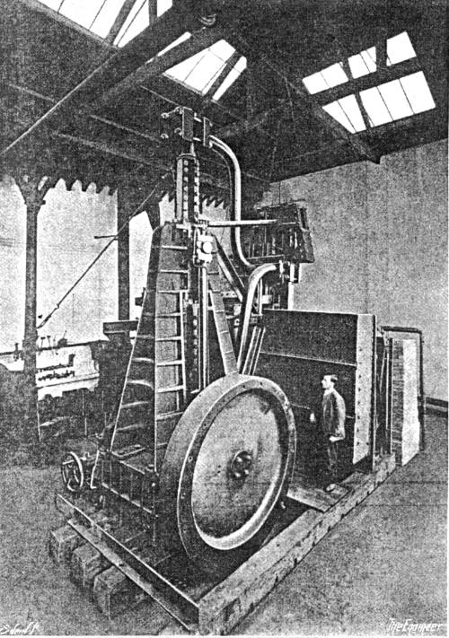 | Left: Malone's first large liquid engine: 1928?
|
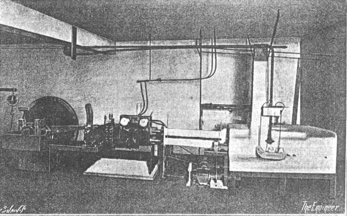 | Left: Malone's small horizontal liquid engine: 1927
|
Malone experimented on the the thermal-expansion coefficients and compressibilities of a range of liquids, including mercury, liquid carbon dioxide, liquid sulphur dioxide, and various hydrocarbons. However he, no doubt wisely, choose water as the operating fluid for most of his liquid engines.
The following description is taken from Time magazine for Monday, 3rd August 1931:
"HOT-WATER ENGINE""By surrounding two cylinders with high pressure boilers, by filling the boiler coils with water and then sealing them hermetically, Engineer J. F. J. Malone of Newcastle-on-Tyne, England has made an effective heat engine. Last week he demonstrated it.
"A furnace heats the base of one boiler-cylinder to 900°F. (688° above water's normal boiling point). The superheated water expands (but cannot change to steam because it is too closely confined) and pushes a piston at the far end of this cylinder. Cold water or air, applied against the piston end of the boiler, cools the confined water sufficiently to make it contract and suck the piston back to its original position. The external cold water or air is shut off, the cooled water in the boiler coils passes into the second cylinder, and newly heated water comes from the furnace to push the piston of the first cylinder again. Thus heat energy carried by the water changes to mechanical energy in that piston. "Claimed thermal efficiency of the Malone engine is 27%. Superheated steam locomotives are 8% efficient; steam marine engines 14.7%; gasoline engines 26%,; Diesels 47%. Once filled the Malone engine needs no more water for long periods of time." |
This describes what is essentially a Stirling-cycle hot-air engine with the air replaced by water, which is kept under such high pressure that it cannot boil even at the high temperatures used.
There seems to have been little contemporary interest in the idea, and Malone appears to have abandoned work on his liquid engine in the mid 1930's, turning his attention to a regenerative gas machine. To this end he formed the The New Engine Company Limited.
![]()
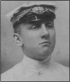 | Left: John Malone: date unknown
|
THE MALONE PRINCIPLE
John Malone was granted US Patent 1,487,664 for a 'Heat Engine'in March 1924. At the time he was living in Newcastle-On-Tyne, England.
 | Left: Malone US patent No 1,487,664: 1924 |
This diagram from the patent shows the general idea of Malone's liquid engine. A liquid (in the patent Malone recommends either mercury or an alloy of mercury and lead) is moved from a cold area to a hot area, where it expands and does work. It is moved by a displacer and passes through a porous regenerator 25 made of 'fine wires', to conserve heat and so improve efficiency; this is a liquid version of a Stirling hot-air engine.
Here the heating is done by gas jets at A and the cooling by water-tank B.
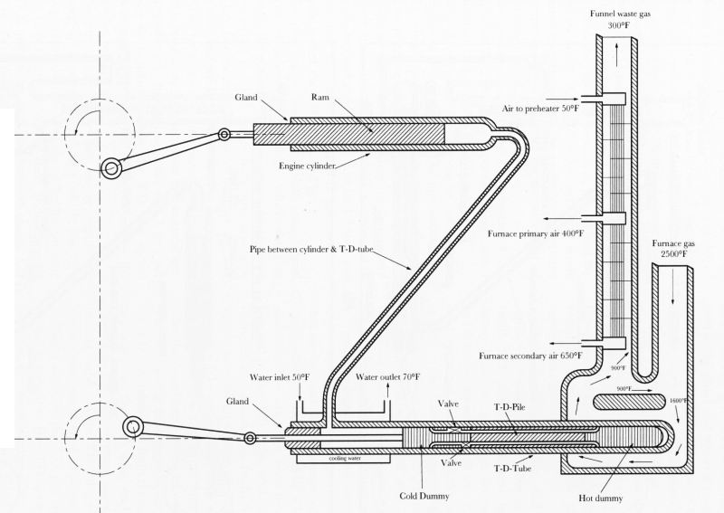 | Left: Malone engine: 1931
|
The principle is the same as for the US patent drawing above, though there are now separate power and displacement cylinders. The working fluid is moved between the heating area at the right and the water-cooling area at the left by the displacer piston, its ends labelled 'cold dummy' and 'hot dummy'. The porous regenerator is labelled 'T-D-pile'; T-D stood for 'ThermoDynamic'.
![]()
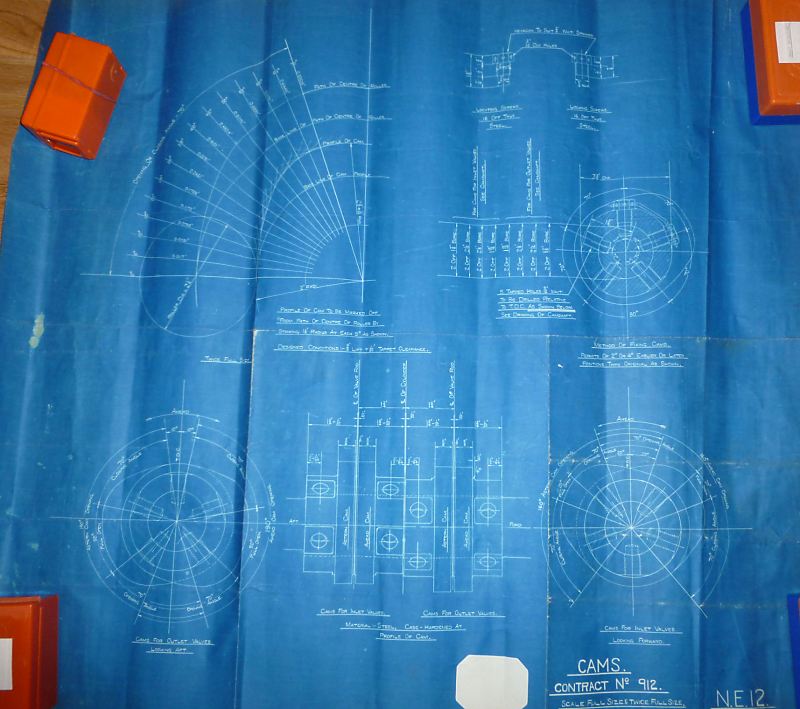
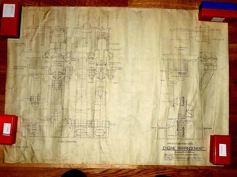
THE MALONE BLUEPRINTS
In August 2015 I was contacted by John Malone, the grandson of JFJ Malone. He pointed out that not all the Malone material was lost, and he had a set of blueprints for one of the engines, apparently dated between 1929 and 1931. With his permission I am going to publish them here.
According to Sier, Malone abandoned development of his liquid engine in the early 1930's, and instead set up 'The New Engine Company Ltd' to develop a new external-combustion marine engine; this company is unknown to Google although there is a contemporay company of the same name which has no apparent connection. No details of this later engine are known, and I suggest that these blueprints may be all that remains of that engine. The fragmentary information on the drawings suggests that it may have been some sort of compound hot-air engine operating at high pressure.
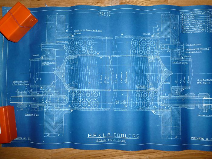 | Left: Malone blueprint No 2
|
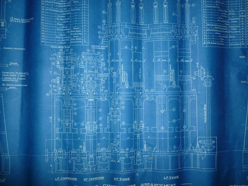 | Left: Malone blueprint No 5
|
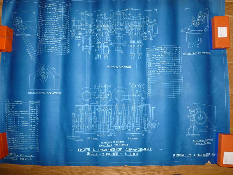 | Left: Malone blueprint No 5, sheet 2
|
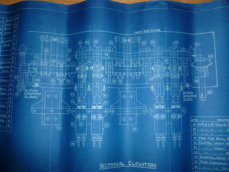 | Left: Malone drawing No 5, sheet 2
|
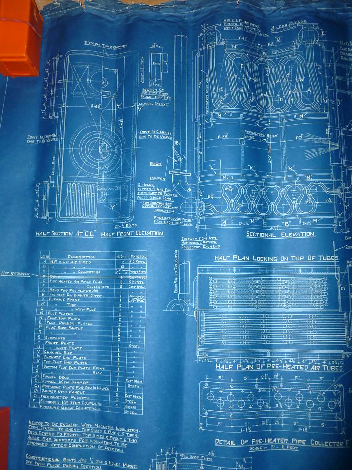 | Left: Malone drawing No ??
|
 | Left: Malone drawing No ??
|
 | Left: Malone drawing No 37/1
|
As we have seen, Malone was not the first to think of a liquid expansion engine; but he does appear to have been the first to actually build one, to measure its performance, and to develop it.
 | Left: Westcott's liquid engine system: 1962
|
 | Left: Westcott's liquid engine, Side elevation: 1962
|
 | Left: Westcott's liquid engine, top view: 1962
|
These earlier US patents were cited in Wescott's 1962 patent:
UNITED STATES PATENTS
226,570Thuemmler 13 Apr 1880'Thermo-Dynamic Engine'
311,102Boulton & Perrett20 Jan 1885'CALORIC ENGINE'
730,248 Friedenthal9 June 1903'STEAM-GENERATOR'
750,494 Schütt26 Jan 1904'GENERATION OF MOTIVE POWER'
1,032,236 Patten9 July 1912
1,426,462 Claude22 Aug 1922
2,471,832 McCollum31 May 1949'INTERNAL-COMBUSTION HEATER WITH KNIPP'S SINGING TUBES' (really!)
2,632,995 Noe31 Mar 1953'FLUID ENERGY TRANSMISSION, CONVERSION, AND STORAGE SYSTEM AND POWER CYCLE THEREFOR'
2,839,046 Kamm17 June 1958 |
THE WHEATLEY ENGINE: 1982
Interest in the Malone cycle disappeared for decades but then revived; in the 1970's John C Wheatley, then a physics professor at the University of California resumed the study of liquid-based engines, with the intention of building heat pumps and refigerators rather than prime movers. He chose propylene as the working fluid. Propylene C3H8 is the 3-carbon analogue of ethylene; it is sometimes called propene, or methyl ethylene. The boiling point is -48 degC, and it is usually stored as a liquid under pressure. Its advantage for this work is that liquid propylene can be raised in temperature by 9 degC if compressed to 2500 psi, a straightforward process.
This work resulted in US patent 4,353,218 granted on 12 Oct 1982.
THE CO2 REFRIGERATOR: 1992
In 1992 the Los Alamos group was working on refrigeration cycles based on Malone's work. One version was built by Dr Swift, using liquid carbon dioxide at 2000 psi as the working fluid.
THE HAGEMAN PATENTS: 1999
Interest in liquid expansion continues. Brian Hageman of Phoenix Arizona was granted US patent 5,899,967 in May 1999, and US patent 5,916,140 in June 1999. Both patent are titled HYDRAULIC ENGINE POWERED BY INTRODUCTION AND REMOVAL OF HEAT FROM A WORKING FLUID but while they are very similiar they are not identical documents. What the point of this was I do not know.
Both patent cite the Westcott Liquid Engine. (see above)
![]()
 | Left: Hageman's liquid engine: 1999
|
![]()

|