Rotary-Valve Internal Combustion Engines
|
| |
Gallery opened Sept 2004
Updated: 5 Apr 2026
The Rex Rotary valve added here
  
| | |
INTRODUCTION
For almost all its history, the preferred valve for the Internal Combustion engine has been the poppet type. (the etymology of the word "poppet" is an interesting study in itself, but a bit off-topic) There are good reasons for this; see the Appendix on the advantages of the poppet valve.
However, many inventors have been attracted by the apparent simplicity and the uniform motion of rotary valves of one kind or another. There is also the tempting prospect of being able to run on inferior fuels because there was no hot exhaust valve always present in the cylinder to trigger pre-ignition. However, as with both steam and IC rotary engines, the simplicity was more apparent than real, and the engineering problems were daunting.
The basic problem, is that the pressures in the cylinder of an internal combustion engine are high, due to both the compression stroke and the explosion of the fuel-air mixture. This produces large forces on the valve system, however it is contrived; the beauty of the poppet valve is that such forces simply push it harder against its seat, and have no effect at all on the valve-actuating mechanism.
However, the geometry of rotary valve systems is inherently different; in the Aspin concept below, the vertical valve cone is pushed up axially against the cylinder head, while the horizontal Cross valve is pressed up against the top half of the bearing surfaces. In both cases this can cause excessive friction and seizure, the root of the problem being that enormous forces are acting on the valve while it is moving.
There were a large number of rotary valve schemes tried, many of which are only known as patents, the practical success or otherwise being lost to history. The first US patents tracked down so far are by Frayer & Howard in 1907 and 1908. Another early patent was in 1911 by Vallillee (Patent 983328) who used a rotating disc. Several other versions by other people were patented later; see the patent list below. In Britain the two systems which gained the most attention were the Aspin vertical rotating valve and the Cross horizontal rotating valve.
Rotary valves were also tried in steam engines, without conspicuous success. See The Paget Locomotive and the Carel engine on the High-Speed Steam Engines page. Not only are rotary valves used in engine design, they have numerous applications including changing the pitch in brass instruments.
This page does not include what are usually called sleeve valves if they do not rotate continuously. The best known reciprocatng sleeve engines were on the Knight principle.

THE CROSSLEY ROTARY VALVE GAS ENGINE: 1886 - 1902
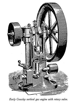 |
| Left: Crossley gas engine with rotary valve.
This is the earliest use of a rotary valve in an internal combustion engine so far discovered. The valve assembly is at the bottom left of the picture, with an adjusting screw sticking out of it. It is driven from the crankshaft by a vertical shaft on the left side of the engine.
Messrs Crossley Bros Ltd (they knew how to name companies in those days) of Openshaw, Manchester, used rotary valves on both vertical and horizontal gas engines running on the Otto cycle. Tube ignition was fitted. Crossley were a successful and respected company, and carried on using these valves from 1886 to 1902; a period of sixteen years that ought to indicate that they worked reasonably effectively and reliably. This is interesting, bearing in mind the problems that later workers struggled with.
The answer is probably that these engines had a very low specific output compared with later designs, and the working pressures were correspondingly low. Also, as a stationary engine, it could be given as much care and adjustment as it needed. In those days it was considered quite normal to give an engine an amount of attention which would be out of the question for, say, a car engine. It was still thought a much better option than a steam engine, where boiler pressure and water level required constant skilled supervision if catastrophe was to be avoided.
Source: Rotary Valve Engines by Marcus Hunter, Hutchinsons 1946
|
The tireless researchers of The Museum have obtained this unique personal account of a Crossley rotary valve engine in use in 1903:
"Although the engine was several years old, it would toil away hour after hour with an occasional application of ordinary cylinder oil to the rotor, oil probably of an inferior grade by modern standards. There is no doubt that the rotary feature was in many ways a most reliable device; that is to say, there was never a mechanical failure of any kind. On a few occasions the rotor would show signs of overheating, and in these circumstances all that was necessary to regain normal running was to remove the keep from the rotary member, clean the working surfaces with paraffin, and start up again with a fresh application of clean oil.
The keep is spring loaded and adjustable. The operation of adjusting the spring had to be most carefully carried out. The exact loading needed to be such that at maximum engine load, and when thoroughly warmed up, the valve was just on the point of spitting at each explosion. If the spring load was too light, the oil would be blown out each time the engine fired, and if too heavy, any extra expansion of the rotor due to increase in temperature resulted in so much additional friction that the ill-effects became cumulative and the engine would begin to lose speed. However, in spite of all this, the Crossley product was a practical engineering job, and there are many modern appliances which give far more trouble."
Testimony by Marcus Hunter, in 1946. This account refers to the vertical engine illustrated above; it was used for driving machine tools in a private workshop
The account above is highly revealing. It shows that the Crossley rotary valve engine required almost constant attention, ongoing and critical adjustment of the valve loading, and periodic dismantling.
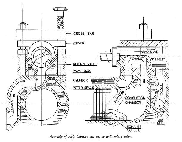 |
| Left: Inside the Crossley rotary valve.
In this version the cylinder bore was 4.5 inches, and the valve bore 3 inches. The cross bar and cover allowed an adjustable pressure to be put on the valve by springs, to maintain sealing. The valve and the valve box were made of ordinary cast iron as generally used for engine cylinders, and indeed all sorts of machinery, at that date.
Note the convoluted gas passages. In particular, the exhaust passage turns back and runs right past the cylinder wall, which does not look as if it would help cooling.
Source: Rotary Valve Engines by Marcus Hunter, Hutchinsons 1946
|
Since 1988 Crossley has been part of the Rolls-Royce Power Engineering group.
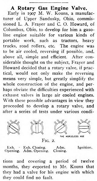
THE FRAYER & HOWARD ROTARY VALVE PATENT: 1907
 |
| Left: Frayer & Howard rotary valve patent: 1907
This is the earliest internal-combustion rotary valve patent so far unearthed by the untiring staff of The Museum. Note however that Butler was apparently using rotary valves in a compound IC engine in 1904.
The valve is mounted horizontally across the top of the cylinder, like the Cross valve, and driven continuously by chain and sprocket from the crankshaft at half-speed.
Frayer and Howard do seem to have had some idea of what they were up against. The valve, shown in Figs 3 and 4, was designed not to touch the surounding metal, but maintain a 2-thou clearance, the gap being flooded with lubricating oil. The valve rotated in ball bearings at each end, protected from the exhaust gases by two sets of sealing rings. (19,20,21,22) It sounds plausible, but I wonder how much oil would be lost into the induction and exhaust passages.
From US Patent 908,656 granted 5 Jan 1909 (Filed in 1907)
|
 |
|  |
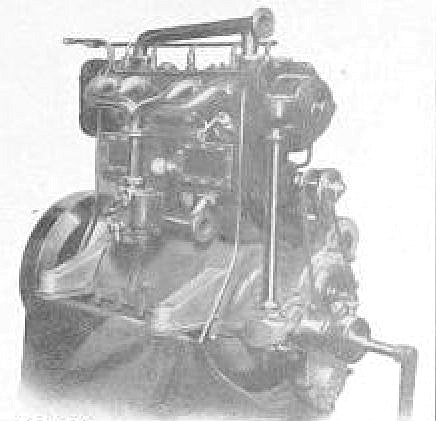
| Far left: Air-cooled engine with Frayer & Howard rotary valve: 1908
Left: Part of article on the Frayer & Howard rotary valve: 1908
The rotary valve is mounted horizontally on top of the four cylinders and is driven through skew gears by the vertical shaft. According to the article, the valve rotated at one-quarter crankshaft speed.
When the article appeared, it stated that preparations were being made for by the Ohio Manufacturing Company, and engines from 12 to 40 HP would be available in 60 days.
From The Horseless Age for 1 April 1908
|
THE OWEN THOMAS ROTARY VALVE ENGINE: 1909
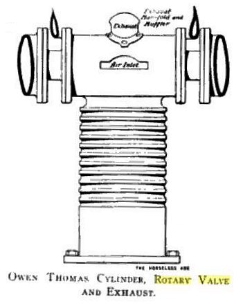 |
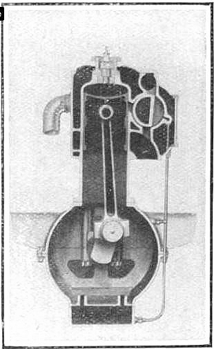
| Left: The Owen Thomas engine: 1909
The Owen Thomas car was built in Janesville, Wisconsin, and appeared at the 1909 Chicago show. It had an air-cooled six-cylinder engine with many advanced features, such fuel injection (apparently based on airship engine practice) and self-starting by a dynamo/motor. The rotary valve was fitted in the cylinder head and was driven from the crankshaft by spiral gears and a vertical shaft. The capacity was 7000 cc. (429 cubic inches) The crankshaft ran in four large ball bearings; additional ball bearings were used in the fan drive, and transmission.
Air-cooling and rotary valves sounds like a bad combination, and note that the cylinder fins were tiny. Apparently there was no throttle in the inlet side; a full charge of air was drawn in every time, and scavenging and internal cooling performed by letting part of it escape before the fuel was injected. How well that worked is unknown, but I would have thought it would certainly increase pumping losses. Power output was controlled by varying the amount of fuel injected, which would surely make maintaining an optimum fuel/air ratio very difficult.
Owen Thomas went out of business in September 1910. I can't say I'm surprised; I imagine they never got the engine working properly.
Source: The Horseless Age: The Automobile Trade Magazine. Volume 23 No 6 p222, 1909
|
ROTARY VALVES BECOME THE VOGUE
In the period 1910-1912 there was a remarkable flurry of activity in the field of rotary valves. Engines using them were unveiled by Itala, Castiglione-Bolton, and Darracq in Europe, and by Mead, Reynolds and The Silent Valve Company in the USA. Rotary valves had, to some extent, become the fashion. But they still did not work very well.
THE BALLOT ROTARY VALVE ENGINE: 1910
 |
| Left: The Ballot engine: 1910
The description of this engine is less than clear in the source. The engine had some sort of hemispherical valve mounted "in the bottom of the cylinder head" and this was apparently oscillated by a cam. If that is correct this is not strictly a rotary-valve engine, where the valve rotates continuously, but it certainly looks like one. The valve shaft is chain-driven at half crankshaft speed.
The Ballot company was a French manufacturer, initially just of engines, but they made sports cars and racing cars from 1919 to 1932, when they were absorbed by Hispano-Suiza. �douard Ballot became known as an engine designer, helping Ettore Bugatti to develope his first engines. Apart from the source below, no other mention of their involvement in unconventional valvegear has so far been found.
Source: La Vie Au Grand Air for December 1910. La Vie Au Grand Air, meaning 'Life in the great outdoors' was a 'magazine of all the sports' which in 1910 clearly included motoring. It was published from 1898 to 1922; more info here.
|
THE BERLIET ROTARY VALVE ENGINE: 1910
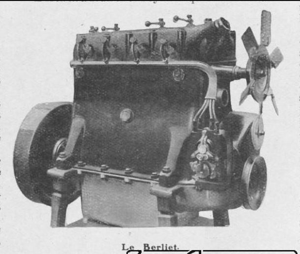 |
| Left: The Berliet engine: 1910
The description of this engine in the source is very hard to understand (quite apart from the fact it's in French) and it is possible that it was actually a sleeve-valve engine. On the other hand the shaft with the fan on the end looks like it might be in the right position to operate a rotary valve in the cylinder head.
Investigations are continuing.
Berliet was a French company that manufactured cars, buses, trucks and military vehicles. It was founded in 1899 and was absorbed into Citroen in 1967.
Source: La Vie Au Grand Air for December 1910
|
THE COTTEREAU ROTARY VALVE ENGINE: 1910
 |
| Left: The Cottereau engine: 1910
The Cottereau company manufactured cars from 1900 to 1914, and in 1911 were testing 4 and 6 cylinder engines with rotary valves
The rotary valve was driven by the vertical shaft seen in the centre of the cylinder block.
Source: La Vie Au Grand Air for December 1910
|
THE HENRIOD ROTARY VALVE ENGINE: 1910
 |
| Left: The Henriod engine: 1910
The Henriod rotary valve system was patented by Swiss automotive engineer Charles-Edouard Henriod. By 1912 he was collaborating with Darracq, but the rotary valve engines were of low power and unreliable.
Henriod were one of the early car manufacturers. In Bienne, Switzerland, Fritz Henriod (Charles' elder brother) built a steam tricycle in 1888, and in 1893 he constructed a car with a one-cylinder petrol engine.
Image source: La Vie Au Grand Air for December 1910
|
UNKNOWN ROTARY VALVE ENGINE: 1910
 |
| Left: Unknown rotary valve engine: 1910
Nothing much is currently known about this engine. Clearly there are four cylinders and a rotary valve running across the top of the cylinder block, driven by the vertical shaft through helical gears. Given the source, it was presumably French.
Source: La Vie Au Grand Air for December 1910
|
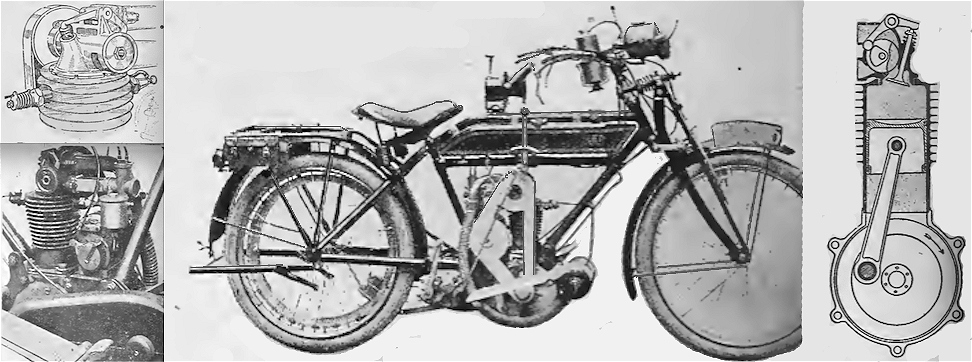
THE REX ROTARY VALVE ENGINE: 1910
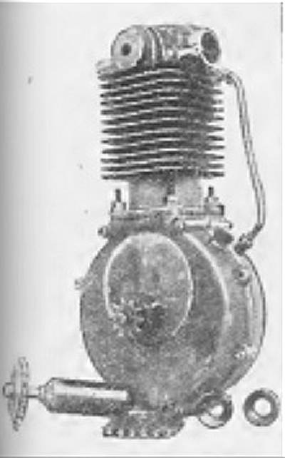 |
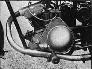
| Left: The Rex rotary valve engine: 1910
Some rotary engines were tried out by the Rex Motorcycle company around 1910. The picture shows the rotary valve removed from the cylinder head and resting at lower left. It appears the valve was driven by a chain at half crankshaft speed. The pipe running up to the cylinder head from the crankcase no doubt carried some much-needed oil to the rotary valve.
There is some more info here
Source: Motorcycle Timeline
|
THE ROBERT ROTARY VALVE TWO-STROKE AERO ENGINE: 1911
 |
| Left: The Robert rotary valve 4-X two-stroke aero engine: 1911
This aero engine was produced by the Roberts Motor Company of Sandusky, Ohio. It worked on the two-stroke cycle, using crankcase compression of the charge by the bottom of the descending piston. Here the crankcase appears to have been divided so that each cylinder has its own compartment, with a horizontal rotary valve that controlled charge distribution from a single carburettor, seen in the middle of the rotary valve. The rotary valve appears to have revolved at crankshaft speed. Since the rotary valve is never subjected to exhaust gases (these leave the cylinder by ports uncovered by the pistons) its design must have been much easier than the four-stroke equivalent. On top of the rotary valve at the left is a gear-driven water-pump.
The company�s founder and president Edmund W. Roberts designed the engines, and was granted US patent 1,210,537 in 1917; however this covers the cylinder construction rather than the rotary valve.
Six-cylinder 6-X engines with two carburettors feeding the rotary valve were also built by Roberts. Their aero engines were used by a good number of early aviation pioneers, but they gave up on making them in 1919, and went out of business a few years later.
There is a lot more information here. This includes the building of two replica 6-X engines to power a Benoist XIV flying boat replica for Fantasy of Flight.
|
This engine is on display in the Smithsonian Museum.
THE VALLILLEE ROTARY VALVE PATENT: 1911
 |
| Left: The Vallillee rotary valve patent: 1911
The rotary valve has an H cross-section and sits on top of the cylinder. It is rotated intermittently via cam 38 and lever 35, that work a ratchet drive 42 on top of the cylinder, the idea presumably being that the valve would be stationary during the parts of the combustion cycle that had high-pressure in the cylinder and would tend to jam the valve.
This is the first known proposal to use intermittent drive to a rotary valve. It looks rather impractical to me.
Leonard Archibal Vallillee lived in Buckingham, in the province of Quebec. Unlike most of the inventors in these pages, he is known to Google. He was born in 1887, the son of John Edward Vallillee (born circa 1863 in Buckingham, Quebec) and Mary McCormick.
From US Patent 983,328, 7 Feb 1911
|
THE ITALA ROTARY VALVE: 1911
Itala was a car manufacturer based in Turin, Italy from 1904-1935. See Itala in Wikipedia. Water-cooled rotary valves were fitted to models announced at the 1911 Olympia Motor Car Show. At first only a 35 HP model was displayed, but 25 and 50 HP versions were said to be on the way.
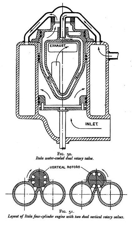 |
| Left: The Itala rotary valve : 1911
Two rotary valves were used, each placed vertically and serving the two adjacent cylinders. Each cylinder had only one port, which carried both inlet and exhaust, while the valve, which turned at one-quarter engine speed, had an internal division so that the inlet was drawn in from the bottom and the exhaust passed out through the top.
Cooling water for the valve passed into it at the centre, passed down one side of the valve body and up the other, and left by an annular port at the top. A centrifugal pump assisted water circulation.
The crankshaft carried a helical gear that drove a side shaft; this in turn drove the two vertical valve spindles through 'high-efficiency' worm gears. Each valve spindle incorporated a breaking-piece (presumably some sort of shear-pin) to minimise damage to the engine if one of the valves seized.
A small hole was drilled through the valve body in such a position that it carried the pressure on firing through to the opposite side of the valve, into a recess of the same area as the valve port, to balance the loading.
Despite ingenious design, high standards of construction, and some very favourable reports (eg from Autocar) the Itala valve did not prosper. Hunter says "...it is evident from a careful study of the design that it calls for the highest grade of materials and workmanship; in fact every technical defect which might be possible seems to have been overcome by lavish expenditure and detail embellishment... these opinions are expressed: (1) there are too many parts, and (2) skilled experience is required for maintenance, greater than can generally be commanded..."
This is all a bit vague; perhaps however it boils down to the Itala rotary valve being expensive and unreliable. I suspect those "breaking-pieces" saw a lot of action.
Source: Rotary Valve Engines by Marcus Hunter, Hutchinsons 1946
|
Rankin Kennedy's "The Book of the Motor Car" published in 1913, had this to say:
"Now for the first time a high-speed multiple cylinder engine without reciprocating parts, is available in a throughly practical form, so well thought out in detail and so beautifully constructed that its possession and use cannot be less satisfactory to the fortunate owner than the contemplation of the design is to the engineering critic." which, quite frankly, is laying it on a bit thick. One can only assume that news of valve troubles had not reached Mr Kennedy before publication.
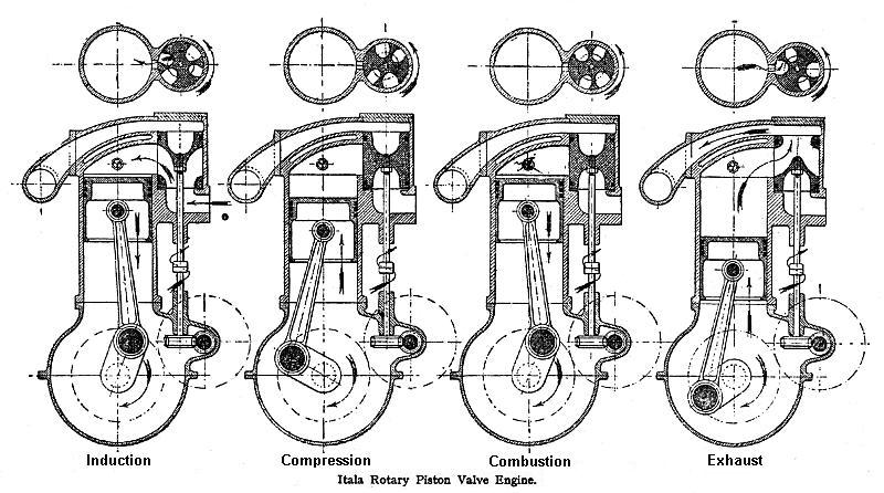 |
| Left: Operating cycle of the Itala rotary valve: 1912
Starting with induction and ending with the exhaust stroke. Note the Oldham coupling in valve shaft. This incorporated the 'breaking piece'.
From The Book of the Motor Car Rankin Kennedy, published Caxton 1913
|
From 1924 the Itala company was being run in receivership. It was bought by truck maker Officine Metallurgiche di Tortona in 1929, and a few more cars were produced, ending in 1935. After that, what was left of the Itala company was bought by Fiat.
THE TIPS ROTARY VALVE: 1911
Sometimes it seems as if the history of yet another rotary valve appears every day. Maurice A Tips and his younger brother Ernest Oscar Tips were pioneer Belgian aviators, building their first aircraft in 1909. It was not very satisfactory, and Maurice turned his attention to aero-engines.
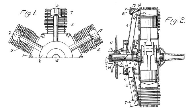 |
| Left: Tips rotary valve aero-engine: 1911
The first Tips engine was a seven-cylinder rotary (in the sense thst the engine went round with the propellor, while the crankshaft was fixed to the airframe) which gave 25 hp (19 kW) at unknown rpm. Each cylinder was fed via a rotating tube that conducted the fuel-air mixture from the crankcase; at the top of each tube was a rotary valve dealing with induction and exhaust. Each tube was driven by a bevel gear meshing with another bevel gear on the crankshaft.
I can tell you now that I am not impressed with Fig 1 of the patent. The cylinder spacing and angles shown would be correct for a six-cylinder radial or rotary engine, but the Tips engine, like all such, had to have an odd number of cylinders to get a sensible firing order. Clearly the draughtsman was too damned idle to work out the co-ordinates for a seven-cylinder drawing.
There is more information at oldmachinepress.com.
Image from US patent 1,051,290 granted Jan 1913
|
Maurice Tips went on to design larger and more complex engines, but all had rotary valves similiar to this arrangement.
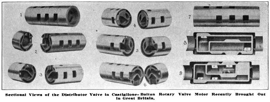
THE CASTIGLIONE-BOLTON ROTARY VALVE: 1912
This British rotary valve scheme was put foreward by Castiglione and Bolton. The valve was horizontal, running the length of the engine
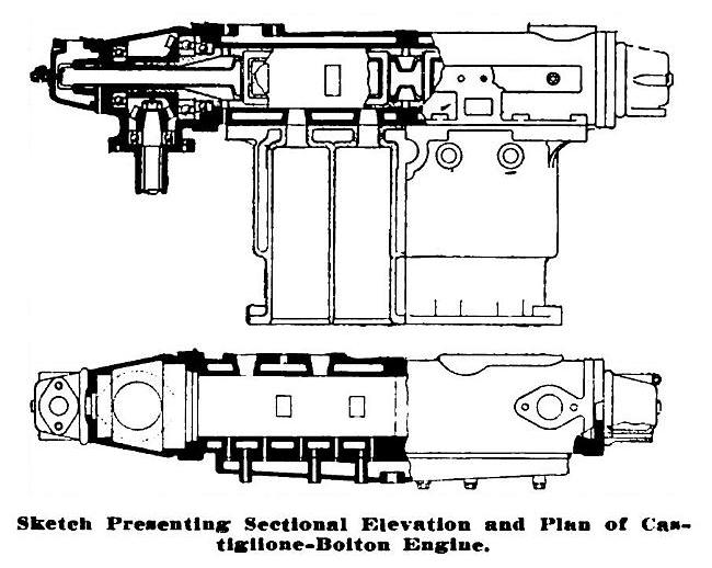 |
| Left: Castiglione-Bolton rotary valve engine: 1912
The rotary valve was driven by a vertical shaft through bevel-gearing. It had a water-cooling jacket on its outside, accessed at each end by pumped cooling water.
Below: The Castiglione-Bolton rotary valve: 1912
The valve had a complex system of inlet and exhaust porting, which connected to the cylinder via a single port in the top of the roughly hemispherical combustion chamber.
The view at 7 is of a complete valve for two cylinders.
From the The Automobile Journal Volume 33. Number 7 May 10, 1912, page 46
|
The engine seems to have had little success, as the Castiglione-Bolton team is unknown to Google. It also seems to have escaped the notice of Hunter.
THE DARRACQ-HENRIOD ROTARY VALVE: 1912
The Darracq-Henrold rotary valve engine was a French design, from the well-known car firm of Darracq. According to one source "In 1912 the firm succumbed to the vogue for abolition of the poppet valve with a near disastrous range of rotary valved cars under Henriod patents." which sounds as if things didn't go too well, and also gives a hint as to why so many rotary valves appeared around 1912- it was "the vogue".
In 1912 Darracq produced "syst�me Henriod" engines of 2613 cc and 15 HP (uprated to 2951 cc the next year) and a 3969cc version of 20 HP.They were described as Type SS, or 'sans soupapes', meaning without valves- not strictly true, of course. Hunter says, apparently acidly, "'Sans soupapes' is the term which the French give to every engine which has other than poppet-valves." These engines were also described as "completely gutless", presumably due to breathing difficulties, and were prone to seizure. Both profits and Darracq's reputation plummeted, and the debacle seems to have prompted Alexandre Darracq to retire from car manufacture; he sold his company to British financial interests in 1913. Apparently one 1912 SS car is still in existence, but in need of restoration. According to Hunter (p102) only a few engines actually reached customers, so for the effect on the company to be so drastic, their performance must have been truly awful.
The company survived and went on to prosper under British management. This gentleman owned both a rotary-valve Itala and a rotary-valve Darracq.
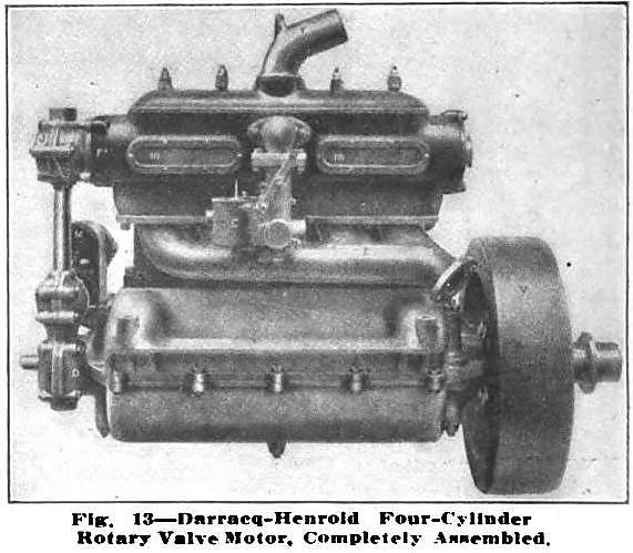 |
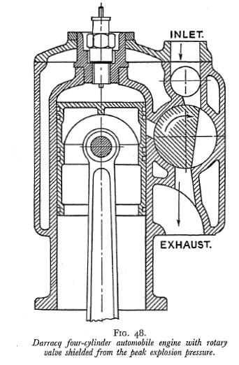
| Left: A Darracq four-cylinder engine with rotary valve: 1912
The horizontal valve ran the length of the cylinder block, being driven from the crankshaft at half engine speed by a vertical shaft with skew gears. The ignition magneto can be seen to the left behind the vertical shaft.
Look at the size of that flywheel! There seems no reason why a rotary-valve engine should need a huge flywheel; perhaps the engine had some other problems.
From The Automobile Journal Volume 33, Number 6, 25 April 1912; p18,19. The article spells Henriod as Henrold throughout.
|
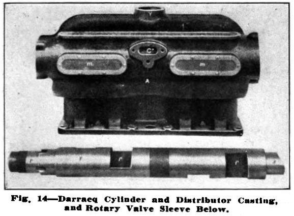 |
| Left: The Darracq rotary valve: 1912
Pretty much self explanatory.
The flange marked C is for mounting the carburettor. The covers m presumably allowed inspection of the valve.
From The Automobile Journal Volume 33, Number 6, 25 April 1912; p18,19.
|
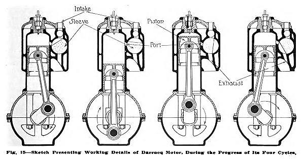 |
| Left: The Darracq rotary valve: 1912
The operation of the valve over a complete cycle.
From The Automobile Journal Volume 33, Number 6, 25 April 1912; p18,19.
|
 |
| Left: The Darracq rotary valve: 1912
Despite its appalling record, the Henriod valve did have features that made it at least plausible.
Unusually, the valve port opened into the side of the bore, so that the valve was cut off from the combustion chamber when the piston was at the top of its stroke. This was supposed to protect the valve from high pressures and temperatures.
Hunter points out two problems: firstly, on changing from exhaust to induction the cut-out section of the valve carries round a quantity of exhaust gas that dilutes the fresh charge, and secondly, on every rotation the this section carries a portion of fresh charge straight round to the exhaust pipe, causing a dead loss. He also points out that because of the position of the valve port below the piston for one-seventh of the stroke, gases would be trapped above the piston. leading to poor volumetric efficiency.
He also criticises "...the omission of a well-thought-out scheme of lubrication..." which certainly sounds like a major error in this difficult field.
Source: Rotary Valve Engines by Marcus Hunter, Hutchinsons 1946
|
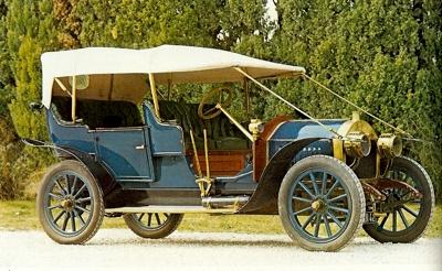 |
| Left: Darracq rotary valve car: 1912
This is believed to be a picture of a Darracq SS of 1912 manufacture. |
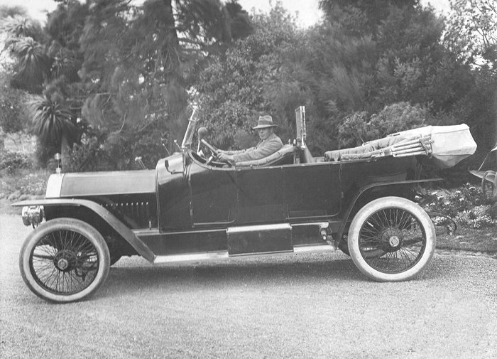 |
| Left: Darracq rotary valve car: 1915
This is (almost) definitely a picture of a rotary-vave Darracq. It shows a 20 HP model on the South Island of New Zealand; it is the only rotary-valve Darracq known to have been exported. Doubts about the look of the radiator have been expressed.
|
Charles-Edouard Henriod (the younger brother of Fritz Henriod, who in 1886 made an experimental steam car, and a petrol car in 1893) was Swiss. In 1898 he began making motorcars in Paris. These had a horizontally-opposed air-cooled engine at the front, a three-speed gear system of bevel-gears and pinions, and final drive by side-chains. Over the years Henriod cars became more orthodox, but Charles-Eduoard could not resist the lure of the unconventional. When he stopped making motorcars he designed his rotary-valve system and patented it.
Another licencee of the Henriod patent was Fernand Charron who used it in his Alda cars. It was no more successful than it had been for Darracq. As the French seem wont to say when something is a complete disaster: "It did not give satisfaction."
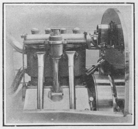
THE REYNOLDS ROTARY VALVE: 1912
The Reynolds Motor Company was based in Detroit. It originally introduced a four-cylinder four-stroke engine with rotary valves, and following "extended tests in various makes of cars with splendid results" they produced the six-cylinder version seen here.
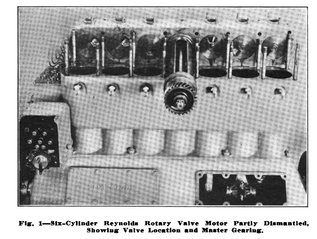 |
| Left: Reynolds rotary valve engine: 1912
The cylinder head has been unbolted and turned on its side. The central shaft with the skew gear on the end was normally vertical, running through the "seventh cylinder" in the middle of the six-cylinder engine.
Apologies for the moire.
US patent 924,382 was granted to R A Reynolds in March 1909
Source: The Automobile Journal, Volume 33, Number 6. 25 April 1912, p13-16
|
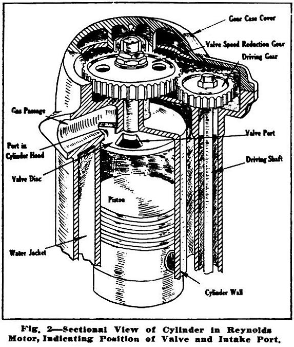 |
| Left: The four-cylinder Reynolds engine: 1911
This shows the vertical valve disc that made up the top of the cylinder. The upward forces on the valve during the firing stroke must have been enormous. This is the end-drive system used in the four-cylinder engine.
The four-cylinder engine had a bore of 3.5 in and a stroke of 4.5 in.
US patent 924,382 was granted to R A Reynolds in March 1909
Source: The Automobile Journal, Volume 33. Number 6 25 April 1912, p13-16
|
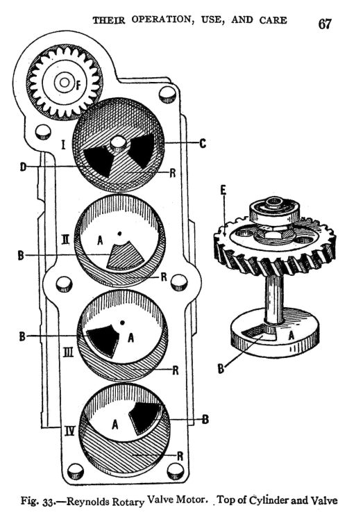 |
| Left: The four-cylinder Reynolds engine: 1912
This image comes from A Hyatt Verrill 'Gasolene Engines' 1912. It clearly relates to the image just below.
|
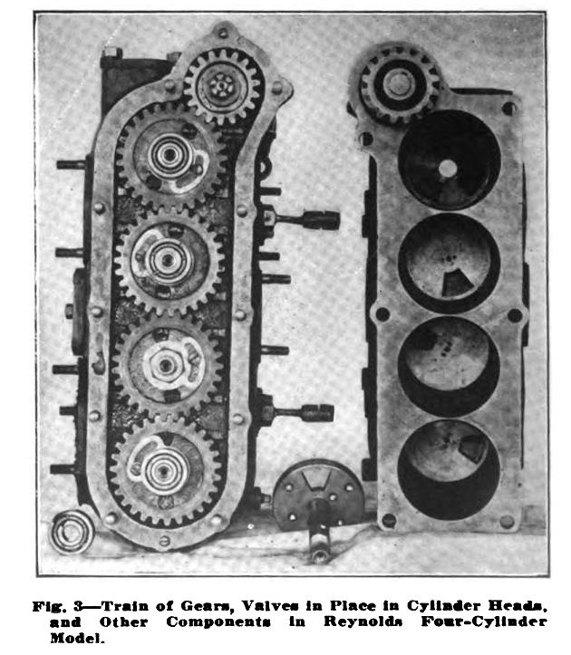 |
| Left: The four-cylinder Reynolds engine: 1911
There was one port in the rotating valve and two in the cylinder head. Note the adjustment built into the drive gears, presumably for tweaking valve timing.
One valve is shown shown removed at bottom centre; we are looking at the top of the valve. The valve stems were bronze. The countersunk holes in the top surface were intended to act as 'oil receptacles'.
US patent 924,382 was granted to R A Reynolds in March 1909
Source: The Automobile Journal, Volume 33. Number 6 25 April 1912, p13-16
|
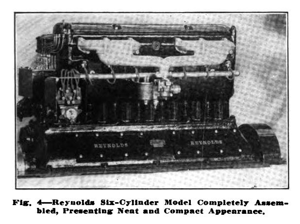 |
| Left: The six-cylinder Reynolds engine: 1912
Note the complex lubrication system at the left end of the block.
The six-cylinder engine had a bore of 4.5 in and a stroke of 6 in.
US patent 924,382 was granted to R A Reynolds in March 1909
Source: The Automobile Journal, Volume 33. Number 6 25 April 1912, p13-16
|
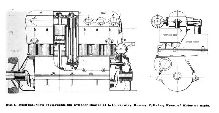 |
| Left: The six-cylinder Reynolds engine: 1912
This drawing shows the vertical shaft running up the centre of the engine, through a "dummy cylinder"; it is driven from a half-speed shaft running parallel to the crankshaft.
US patent 924,382 was granted to R A Reynolds in March 1909
Source: The Automobile Journal, Volume 33. Number 6 25 April 1912, p13-16
|
The big square box visible in the end-drawing above is labelled "force feed oiler", reinforcing the impression that lubrication was really, really important for these engines.
 |
| Left: Reynolds engine: 1912
This Reynolds engine is in the Museum of American Speed. No further information is given on their website.
The force-feed oiler is the square black box at the left. Note four pipes running from it into the top of the engine; presumably one pipe for each valve.
|
THE MEAD ROTARY VALVE: 1912
According to the Boston Evening Transcript of 8th March 1913, the Mead rotary valve was the result of seven years of experimental work by Cyrus W Mead, and represented nearly a quarter of a million dollars in expenditure.
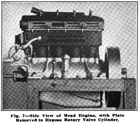 |
| Left: Mead rotary valve engine: 1912
The Mead valve system used two small-diameter valves running longitudinally along each side of the cylinder block. Here one valve can be seen with its cover plate removed. Note once again the fat weighty flywheel.
The Boston Evening Transcript stated that the valve was provided with "liberal cooling". It also said that Mr Mead had made many experiments on lubrication and finally adopted the method of adding 5% of lubricating oil to the fuel; this was presumably in addition to normal sump-based lubrication, and does not inspire confidence, in me at least. I am not sure how it would get oil to the exhaust valve, which no doubt needed it most. At any rate, it must have been a nuisance for the owners.
Apologies for the moire on the picture.
Picture source: The article "Non Poppet Valve Motor Design" in The Automobile Journal 10 April 1912, volume 33, Number 5, p17,18.
I understand the same image appears in a Society of Automobile Engineers (SAE) paper by Mead, No 110030, entitled 'A rotary valve gasoline motor'.
At about the same time, another SAE paper, No 120011, by J B Hull, entitled: 'Non-Poppet Valve Motors at the 1911 Olympia Show' was published, I understand, however, that it has no images.
|
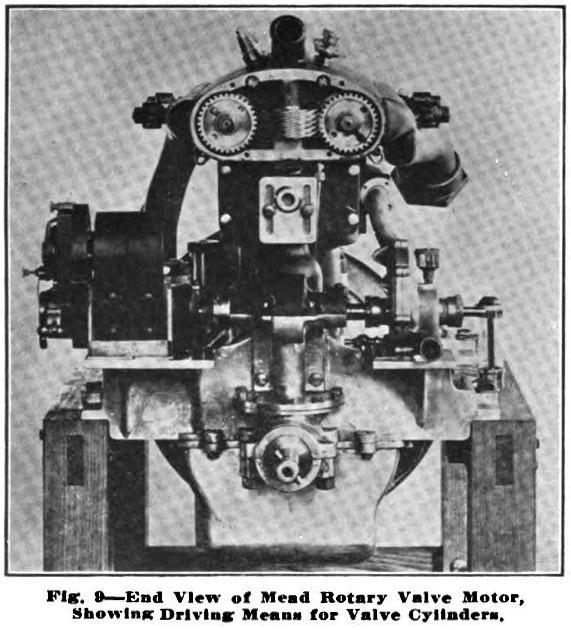 |
| Left: Mead rotary valve engine: 1912
The drive to the two valves, via a vertical shaft and skew gears. The ignition magneto is to the left and the cooling-water pump on the right; both are apparently also driven from the vertical shaft.
The Boston Evening Transcript also claimed that: "In the past few years a great many of these motors have been built and put into operation. They have been subjected to the most severe tests possible... The motors have been run in cars several hundred thousand miles, and they have been run on dynamometers for long periods of time, and many of the tests were at high speed and high horsepower without stop for several days."
Now if all that was really true, the Mead valve would appear to have been thoroughly reliable and a great success. But I am skeptical, I fear.
Picture source: The article "Non Poppet Valve Motor Design" in The Automobile Journal 10 April 1912, volume 33, Number 5, p17,18. Apologies for the moire.
|
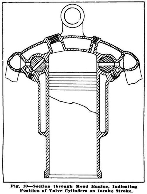 |
| Left: Mead rotary valve engine: 1912
Note the very narrow passages through the valves for both induction and exhaust. Does not look promising for good breathing.
There appear to threaded holes for fitting oil-pipes underneath each valve, which is curious in view of the oil-in-fuel lubrication scheme mentioned above.
Mead's SAE paper says, adjacent to this illustration, "The sketch herewith shows the very fortunate shape of the explosion chamber and the easy passage of inlet and exhaust gases." which I have to confess I find unconvincing. I have no comment to make on the shape of the combustion chamber, but the passages through the valves look like relatively narrow slits. I appreciate they are, like the famous symbol, longer than they are wide, but I strongly doubt if they gave free passage to gases. I suspect that the valve passages had to be slit-like for the valves to open and close at the right moment. The same slits can be seen in the Speedwell engine valve shaft, below, but then that engine did use the same Mead patents, so it is hardly surprising.
The round thing on top is not a lifting eye, but a representation of the cooling water connection.
Mead was granted US patent 1,007,040 in October 1911.
Picture source: The article "Non Poppet Valve Motor Design" in The Automobile Journal 10 April 1912, volume 33, Number 5, p17,18
|
THE SILENT VALVE COMPANY: 1912
The Silent Valve Company was based in Connersville, Indiana. The Silent Valve engine was designed by Edwin L Russell, who worked on it for 10 years before achieving something like success. The 'Silent' bit refers to the fact that rotary valves had no tappets to rattle- a common source of noise in early engines.
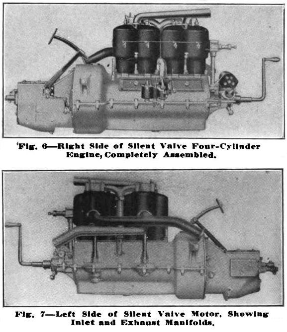 |
| Left: Silent Valve Company engine: 1912
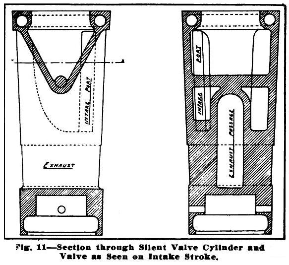
The Silent Valve engine had two vertical conical valves, each one shared between two cylinders, and rotated at one-quarter engine speed, like the Itala valve described above. The cylinder bore was 4.5 in and the piston stroke 5.5 in.
The two vertical drive shafts for the valves can be seen in the lower picture.
US patent 1,284,463 was granted to Russell in November 1918.
Source: The Automobile Journal, Volume 33. Number 6, 25 April 1912, p16-18
|
 |
| Left: Silent Valve Company engine: 1912
Source: The Automobile Journal, Volume 33. Number 6, 25 April 1912, p16-18
|
 |
| Left: Silent Valve Company engine: 1912
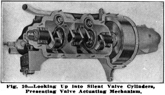
Note the two unusual skew gears on the crankshaft; despite being much larger than the gears at the bottom of the vertical shafts, they have to drive them at one-quarter speed.
Source: The Automobile Journal, Volume 33. Number 6, 25 April 1912, p16-18
|
 |
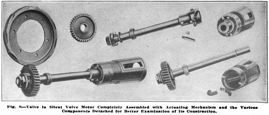
| Left: Silent Valve Company engine: 1912
Hunter points out in the The Automobile Journal that conical valves may be easy to grind to be gas-tight, but are likely to jam in their seatings.
Source: The Automobile Journal, Volume 33. Number 6, 25 April 1912, p16-18
|
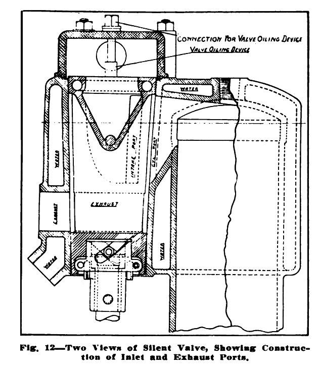 |
| Left: Silent Valve Company engine: 1912
The lower part of the valve is driven from the shaft by a spiral grooved collar. The idea was that if the valve began to stick, the grooves would force it upwards slightly so it ran freely in its seating.
No information is currently available on the "valve oiling device".
Source: The Automobile Journal, Volume 33. Number 6, 25 April 1912, p16-18
|
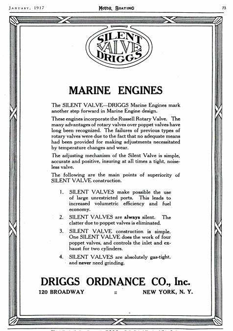 |
| Left: Silent Valve Company engine: 1917
This advert seems to indicate that Russell got into some arrangement with the Driggs Ordnance Company (note the combined logo) to promote marine applications of his rotary valve.
Driggs was more commonly known as the Driggs-Seabury Ordnance Company. According to Wikipedia "Driggs folded for good in 1925" so getting involved with rotary valves doesn't seem to have helped them much.
Source: Motor Boating, Jan 1917
|
No more is known about the success of this plan, but it seems very likely that the valves would be prone to seizing.
Google is silent on the Silent Valve Company.
THE CHARTER ROTARY VALVE: 1914
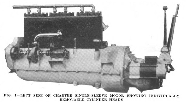 |
| Left: Charter straight-eight engine with rotary valve: 1914
This six-cylinder engine by James A Charter was displayed at the 1914 Chicago motor show, as was the Shaw engine below. It was shown under the name of The Charter Single-Sleeve Motor Co, Chicago.
Each cylinder had a rotating vertical sleeve valve between the water-jacket and a fixed inner sleeve in which the piston operated. Each valve sleeve had two ports and rotated at one-quarter of crankshaft speed. The inner and outer surfaces of the valve had spiral grooves intended to distribute oil over the whole length of the valve. The sleeves were rotated by skew gears from a horizontal shaft that was driven from the crankshaft by spur gears, at crankshaft speed. This shaft is on the far side of the engine; on this side can be seen the water-pump and the magneto. The crankshaft had four bearings and pressure lubrication was provided by a gear pump in the crankcase.
Charter claimed an output of 55 HP at 2400 rpm from this engine. The design was said to be of two year's standing and had been tested on the road for the last 6 months.
The article stated that: "This is the first non-poppet valve motor seen in America using the rotating sleeve, though there has been one example of it in France, the CLC, introduced some years ago and seen on the road today." You will note that CLC does not appear in the list of rotary valves at the start of this page; clearly more research is required...
Source: Motor Age for 29 Jan 1914
|
 |
| Left: Charter rotary valve patent: 1929
Here the rotating sleeve valve 14 can be seen between the inner liner 22 and the water-jacket 4.
At left is the horizontal shaft 18 that rotates the valves; it is driven from the crankshaft by the spur gears 20.
The spiral groove for lubrication can be seen.
James Charter was granted US patent 1,718,775 on 25 June 1929- a long time after the Chicago show in 1914.
|
THE SHAW ROTARY VALVE: 1914
The Shaw Motor Company of Chicago exhibited this eight-cylinder rotary-valve engine at the Chicago motor show, reported by Horseless Age in January 1914.
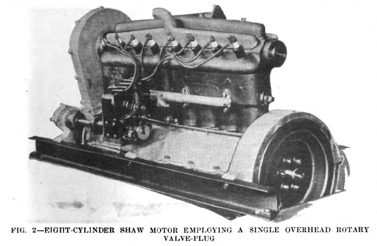 |
| Left: Shaw straight-eight engine with rotary valve: 1914
A horizontal rotary valve ran across the tops of the eight cylinders, and was driven from the front of the engine by an enclosed silent chain.
It was reported:
"Lubrication of this revolving member and its bearing surface is taken care of by mixing the oil with the fuel as in other rotary valve types. The valve case is waterjacketed entirely around the plug not only with the aim of keeping the plug cool but with the idea of protecting it from the heat of explosion."
This does not sound a promising way of lubricating a part under much pressure and thermal stress; I don't know about 'other rotary valve types' but it is the first reference I have seen to petroil lubrication for this type of engine.
The engine was claimed to give 60 HP at 5000 rpm, which was very fast for the time, allegedly made possible by the rotary valve.
Source: Motor Age for 29 Jan 1914
|
Searching for the Shaw Motor Company has so far yielded nothing. Looking for patents revealed a James Shaw of Atchison, California, who was granted US patent 1,066,762 for a 'rotary valve' on 8 July 1913. California is a long way from Chicago but everything else looks right; enquiries are proceeding.
THE SPEEDWELL ROTARY SIX: 1915
According to Motor Age, by the end of 1914 the Speedwell was the only car on the American market with a rotary valve engine, and they were planning to keep it for the 1915 season. This sounds as though it must have been working reasonably well, though it might also have meant that the company was on the brink of bankruptcy and had no money to re-tool a bad design. It also implies that the Shaw rotary valve above did not last out the year.
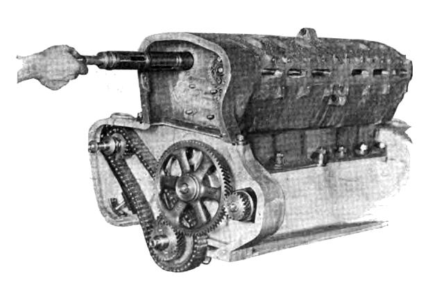 |
| Left: Speedwell in-line six engine: 1915
The disembodied hand is inserting one of the longitudinal valves into the cylinder block. The gearing on display is said to be the timing drive, but it is not clear how it turns the two valve shafts at the top of the block.
The Speedwell engine used a mixture of pump-pressure lubrication for the rotary valves, with splash lubrication of the cylinders. According to Motor Age the valves were grooved longitudinally to distribute lubrication, and this was the vital advance over earlier rotary valve schemes.
Source: Motor Age, 19 Nov 1914, p16-18
|
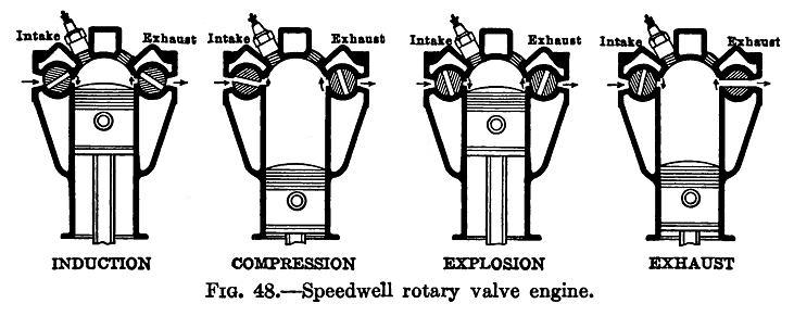 |
| Left: Operation of Speedwell valve
The Speedwell engine used the Mead patents. (see above for Mead)
Source: The Gasoline Automobile by George Hobbs and Ben Elliott, published McGraw-Hill 1915. p34,35
|
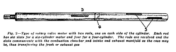 |
| Left: A Speedwell valve shaft
There appears to be some sort of joint in the middle.
Source: Motor Age 17 Dec 1914. p34,35
|
The Speedwell Motor Car Company was based in Dayton, Ohio. It appears to have succumbed to the Great Dayton Flood rather than troubles with its rotary valves.
THE MUELLER & SCHULER ROTARY VALVE PATENT: 1914
 |
| Left: Mueller & Schuler rotary valve patent: 1914
The Mueller patent is the first appearance of a Geneva or Maltese-cross start-stop drive to the valves, though the basic principle was anticipated by Vallillee with his rather implausible ratchet drive, shown above. The Maltese-cross scheme reappeared several times at later dates, for example in the Mellors rotary valve system.
This shows a plan of the cylinder head, with the drive arrangements for the valves of two adjacent cylinders.
US Patent 1,098,679
|
 |
| Left: Mueller & Schuler rotary valve patent: 1914
The horizontal shaft drove two Maltese-cross mechanisms via bevel gears to index the valves of two of the cylinders in a four-cylinder engine.
The text of the patent makes no reference at all to lubrication. Bearing in mind the problems that other workers in the field had with this, it suggests that Mueller & Schuler had not got very far with practical engine development.
Paul Mueller and Ludwig Schuler lived in Brooklyn, New York. Their patent was assigned to the L-M-S Motor Company of Esopus, New York.
US Patent 1,098,679
|
A GRAPHITE ROTARY VALVE: 1917
This rotary valve system was described in the 1917 August-September issue of La Science et la Vie, a French journal that continues being published today. The article describes a vertical rotary valve made of pure graphite, which would be both resistant to heat and self-lubricating. Unfortunately the article gives no mention of who was putting forward this system, but research is in hand...
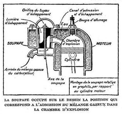 |
| Left: Vertical rotary valve made of graphite: 1917
The valve is rotated by a vertical shaft, presumably driven from the crankshaft by helical gears, like the Reynolds engine shown above. In the illustration the valve is permitting communication between the inlet manifold and the cylinder. The exhaust escapes upwards through the valve when it has turned through 180 degrees. Note the valve is surrounded by water-cooling.
|
THE GRI ROTARY VALVE: 1920
The Gri (named for its designer, George R Inshaw of Glasgow, 1888-1951) had a 3 HP four-stroke single cylinder which most unusually had a rotary valve and a poppet valve. The motorcycles were built from 1920 to 1922 and were distributed by the company Macrae and Dick of Inverness, Scotland.
 |
| Left: Hybrid rotary and poppet-valve engine: 1920
As The Motorcycle put it:
"The flow of gases is controlled by a rotary distribution valve in conjunction with a single overhead poppet valve."
Top left: �The poppet valve is operated through a rocker from a cam on the ball bearing rotary valve.�
Bottom left: "A detachable head, screwed into the cylinder, houses the chain-driven rotary valve and cam."
Centre: "The Gri 3hp motor cycle, which incorporates an unusual type of four-stroke power unit."
Right: "Section of the Gri engine, showing valve gear; the exhaust stroke is nearing completion."
Source: The Motorcyclle 1920, day and month unknown
|
 |
| Left: Hybrid rotary and poppet-valve engine: 1920
The air/fuel mixture enters the cylinder through the poppet valve, which communicates with the carburettor via the rotary valve. After the power stroke, the exhaust gases leave by the poppet valve as they came in, but are now directed to the exhaust sytem as the rotary valve has turned. The poppet valve is driven by a cam on the rotary valve shaft.
Nowhere in the patent does it say why this arrangement is better than the either an all-poppet or an all-rotary engine. It looks as though the presence of the poppet valve would protect the rotary valve from the worst of the heat and pressure, but Mr Inshaw does not say so.
Inshaw also designed the Inshaw Rotary Engine; it was designed and constructed at the works of the Gnome and Le Rhone Company Ltd in Walthamstow, who were well-known for making aero-engines. (This appears to have been an engine where the cylinders rotated around a stationary crankshaft, a common technique for early aero engines, rather than something like a Wankel) There is more information about him here. He took out US Patent 1,292,324 "Packing For Rotary Engines", which I must admit sounds like something for a Wankel-type engine.
Thanks to Steven McDonald for bringing this engine to my attention.
|
THE CROSS ROTARY VALVE SYSTEM: 1920-1940
Roland Cross was undoubtedly the great British exponent of the horizontal rotary valve, and he appears to have got nearer to making it work properly than anyone else. Cross began his work on rotary valve engines in 1920. The project lapsed in 1945, squeezed out by the demand for components from his company for conventional aero-engines. He died in 1970.
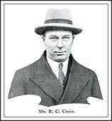 |
| Left: Roland C Cross looking quietly confident
|
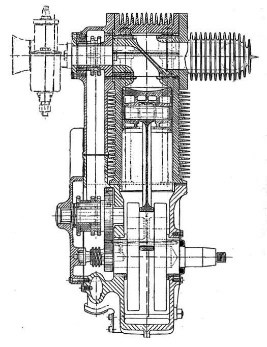 |
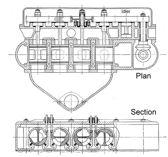
| Left: Cross section of an early Cross rotary valve engine
This shows the basic principle of the Cross rotary valve. It is believed to be a drawing of the "Cross engine with split rotary valve housing" shown below, this judgement being based on the enclosed chain drive and the shape of the finned exhaust manifold.
The induction path goes through the centre of the valve drive sprocket at top left, while the exhaust goes out at top right. Note the very short inlet and exhaust paths, which were supposed to give the high specific output claimed for this engine. Another interesting point is that the 2:1 reduction required for the valve drive is achieved by a pair of gears driven from the crankshaft, and the chain drive is 1:1. The earlier engine with the "solid valve housing" shown below has a chain drive with a 2:1 ratio, eliminating the gears. Why this simpler arrangement was departed from is not currently clear, but it might have been done so that the engine height was not unduly increased, allowing it to fit into an existing motorcycle frame for testing.
The small gear to the left of the lower chain sprocket appears to be the magneto drive. The worm gear on the left end of the crankshaft presumably drove an oil pump- forced lubrication of the valve was very important.
According to Hunter the valve was made of aluminium, with a nitralloy steel shell.
|
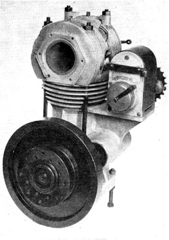 |
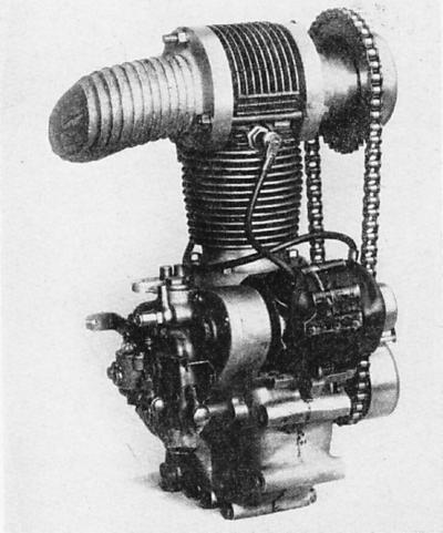
| Left: The first Cross rotary valve engine: 1922
Remarkably, this prototype was not an adaption of an existing poppet-valve engine but was designed from scratch. According to Cross, "It gave plenty of power at high speed but very little at low speed, because of leakage, and it was difficult to start because of the over-large valve and the gas leakage."
The second Cross engine was an adaption of of an overhead-camshaft 500cc Sunbeam motor-cycle engine. Cross says "The rotary valve assembly had a sealing device consisting of piston rings on each end of the valve, and a vane on either side of the port running coaxially with the valve.... The machine would start easily and perform well, being a flexible road machine, yet would lap Brooklands track at a speed of over 80 mph, which was good for those days. The sealing device was not fully effective until the machine had done a few hundred miles and some carbon had filled in the gaps left by the machining".
The oil consumption of these early engines was excessive, but Roland Cross was on the case...
From "Address by the Chairman of the Automobile Division: Experiments with Internal-Combustion Engines" by Roland C Cross, delivered at a General Meeting of the Institute of Mechanical Engineers, 8th Oct 1957
|
 |
| Left: Rotary valves applied to a Rhodes car engine: circa 1925
Around 1925 Roland Cross adapted a 1100cc water-cooled Rhodes car engine to use horizontal rotary valves. He says: "That machine also performed well, was exceedingly smooth and quiet, and would achieve a speed of about 70 mph on any good road".
The rotary valves were connected to each other via herring-bone spur gears, and were driven by a vertical shaft which presumably interfaced at its lower end with the crankshaft by means of bevel gears. At the top of this vertical shaft more bevel gears drove a short horizontal shaft which drove an idler gear (labelled on the drawing) of twice the size, to reduce the valve speed by 1:2 as required.
From "Address by the Chairman of the Automobile Division: Experiments with Internal-Combustion Engines" by Roland C Cross, delivered at a General Meeting of the Institute of Mechanical Engineers, 8th Oct 1957
|
 |
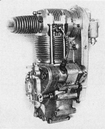
| Left: Cross engine with solid rotary valve housing: circa 1930?
Cross developed his rotary valve by bushing the inside of the valve housing with phosphor-bronze and forming the cylinder port in this bush, The edges of the port were sprung towards the valve and gave a better and simpler seal that could accomodate thermal expansion and contraction of the valve. This construction was the basis of experiment until 1935, when the controlled valve loading scheme was evolved.
At the same time he developed a recirculating lubrication system for the valve, which reduced the previously excessive oil consumption until it was competitive with a conventional poppet-valve engine. This oil system was used on all subsequent engines.
From "Address by the Chairman of the Automobile Division: Experiments with Internal-Combustion Engines" by Roland C Cross, delivered at a General Meeting of the Institute of Mechanical Engineers, 8th Oct 1957
|
Then came the most significant development. Roland Cross: "Towards the end of 1935 I tried the idea of splitting the valve housing along its horizontal centre-line, holding the top half with four long bolts to the crankcase and allowing the cylinder to float vertically. Under the influence of gas pressure in the cylinder, the valve was thus trapped between two halves of the valve housing. The effect of that modification was remarkable. These engines now had wonderful gase sealing, and the slow pulling rivalled that of the steam engine. Seizure was eliminated (which seems to indicate that seizure was not unknown with the earlier versions- DS) and the bearing metal for the valve was the same metal as that of the cylinder."
 |
| Left: Cross engine with split rotary valve housing: circa 1935
This 500cc single-cylinder engine completed a 10-hour test at 6000 rpm.
Note there are four bolts joining the top of the valve housing and the crankcase. The chain drive to the valve is now decently enclosed; the carburettor can be seen at extreme top right.
From "Address by the Chairman of the Automobile Division: Experiments with Internal-Combustion Engines" by Roland C Cross, delivered at a General Meeting of the Institute of Mechanical Engineers, 8th Oct 1957
|
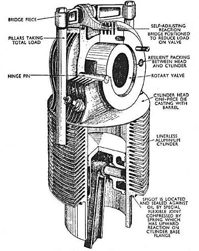 |
| Left: The Cross rotary valve: circa 1935
This is one of the later Cross designs, from around 1935. This version has only two bolts joining the top of the valve housing and the crankcase.
The "reaction bridge" shown in the picture at left absorbs the upward forces on the horizontal valve assembly, and is supposed to have reduced the gas forces on the actual valve. At the moment I'm not quite sure I understand how it worked.
One problem was fouling of the spark plug by oil sprayed from the rotating valve; wiping seals were added to later versions of the engine to control this.
The split valve housing permitted a balanced loading system to control the forces on the valve. Wear was compensated for, lubrication and oil recovery were good, and it is reported that there was no danger of seizure. The sealing problems that other approaches suffered from were solved, and there seems possible that Cross had an effective and practical design which under other circumstances could have reached quantity production; it would probably have been more profitable than the Wankel if it had. On the other hand, Norton had very little success with a similiar concept- see below.
Unlike the Aspin, the Cross valve was always driven at constant speed from the crankshaft.
|
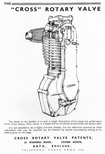 |
| Left: The cover of a booklet the Cross company published to publicise their rotary valve system. Date unknown, but some time after 1935
Note that Combe Down phone numbers only had three digits in those days.
Cross entered two rotary valve motorcycles in the 1935 TT races on the Isle of Man, but one machine proved too slow to qualify, while the other withdrew after two laps with "sparkplug trouble" which may well refer to the problems with plug oiling mentioned above.
|
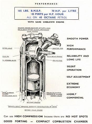 |
| Left: One of the inner pages of the booklet the Cross company published
The performance and fuel consumption figures claimed here were remarkably good for their day. Whether the engines were ever subjected to impartial testing is not currently known.
At least one Cross rotary-valve motorcycle is known to exist in running order; it is brought to a vintage vehicle rally each year by an ex-Cross employee.
|
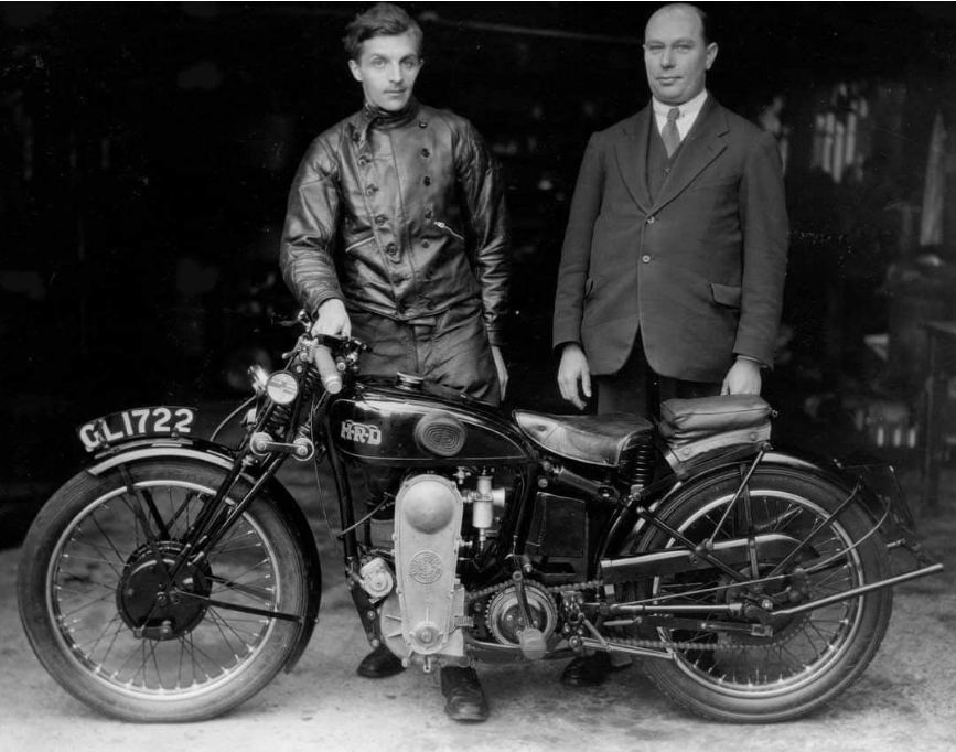 |
| Left: Frank Milsom and Roland Cross with a rotary-valve motorbike: 1934
This excellent photograph was taken outside the Patrick Alexander building at Bath Works and shows Frank Milsom (left) and Roland Cross (right) with GL 1722, an HRD/Cross 500cc Rotary Valve motorcycle. Frank Milsom was Chief Tester for Roland Cross; he was an Isle-of-Man TT rider living in Bath and here is wearing his racing leathers. Unfortunately it appears that Milsom died in a a motorcycle accident in April 1935, while testing a rotary-valve motorbike near Bath, quite probably this one.
The photograph can be accurately dated as 1934 with the machine as supplied and registered to Mr Roland Cross on 15th August of that year. Purchased from HRD as a Model P �rolling chassis� (frame, wheels, petrol tank, handlebars, saddle, etc.), from information provided by the late John Mellor of Vincent/HRD Owners Club, it was built by Ted Hampshire, known for producing their racing bike frames and �signed off� for delivery on 6th July 1934 by none other than Phil Irving himself. It was then fitted with a 500cc Cross Rotary Valve engine driving through a Burman four speed foot-change gearbox. This motorcycle in its developed form mid-1930s was to achieve almost 100 mph at 7,500 rpm at 10.5 to 1 compression ratio. This motorcycle, of immense historical importance, remains in the ownership of Cross Manufacturing Company and is on show in the Company Museum.
At least one Cross rotary-valve motorcycle is known to exist in running order; it is brought to a vintage vehicle rally each year by an ex-Cross employee.
|
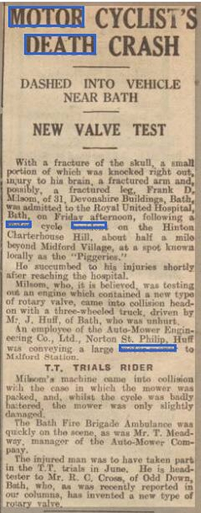 |
| Left: Newspaper account of the death of Frank Milsom in an accident: 1934
This confirms that Frank Milsom sadly died in a motorcycle accident while testing a machine fitted with the Cross rotary valve. Losing the Chief Tester probably did not help with the development of the rotary valve.
Source: Bath Chronicle and Weekly Gazette for Saturday 06 April 1935
|
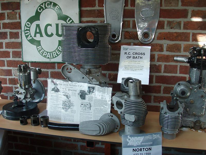 |
| Left: A contemporary display of Cross prototype engines and components at the Sammy Miller Museum in Hampshire
Photograph by Chris Pitt. Used with permission.
Cross evolved a process for the manufacture of high performance piston rings from wire for his rotary valve engine. I am glad to report that the company he founded to make these still exists. See the Cross Manufacturing Company, and look at "history" under the Overview tab. The Cross family continues to be deeply involved, with the third generation continuing the engineering tradition started by their grandfather, working alongside Rodney Cross, surviving son of the founder.
|
There is https://500race.org/people/dick-caesar/">here.
THE MINERVA ROTARY VALVE SYSTEM: 1925
This rotary valve was used by the Minerva Company, who made luxury motorcars in Belgium. There is some more information on the company here; (external link) it says they made Knight double-sleeve valve engines under licence, but strangely fails to mention rotary valves at all. The valve was invented by M. Bournonville, a Belgian engineer; after two years of development work Minerva believed they had an engine that could challenge the Knight sleeve-valve type, and which was of greater reliability than they had seen before. The Minerva-Bournonville rotary valve is mentioned in "Modern Aviation Engines" By Major Victor Page (Norman Henley Publishing Company) in 1929, so it was still live issue at that date.
 |
| Left: The Minerva-Bournonville rotary valve
According to Newton & Steeds:
"It has shown under severe test conditions remarkable reliability and freedom from any tendency to seize up or give trouble through scoring."
From The Motor Vehicle by Newton & Steeds, pub Iliffe, date unknown but certainly post-1921, p71
|
Reference: Automobile Engineering Vol XVII No228 1927-5
The rotating valve-block V ran horizontally across the top of the engine, and had ports R which allowed the inlet manifold I and the exhaust manifold E to communicate with the cylinder at the right time. Each valve-block V was pressed against its seating by two segmental saddles, on the top which bore a wedge W through two steel balls to ensure uniform distribution of the pressure; the spring-loading on W could be adjusted by screw and lock-nut S.
 |
| Left: The Minerva-Bournonville engine
This is believed to be a drawing of a Minerva-Bournonville rotary valve engine. Confusingly it appears to have seven cylinders, but what looks like a connecting rod in the centre of the crankshaft is actually a structure supporting a central crankshaft bearing. Minerva made fours, sixes, and straight-eight engines.
The Japan Society of Mechanical Engineers
|
For a six-cylinder engine two valve blocks were provided, each serving three cylinders. Because of the multiple ports spaced at 120 degrees, the valves only had to rotate at one-sixth engine speed, which must have reduced problems with wear. Drive was by a double roller chain from a gear-driven countershaft running at one third engine speed.
 |
| Left: The Minerva-Bournonville valve
This shows the valve partially withdrawn from the cylinder block. The two saddles can be seen on top of the block.
The Japan Society of Mechanical Engineers
|
 |
| Left: Prototype Rotary car with Bournonville valve engine
Eugene Bournonville was a Belgian minig engineer who made his fortune by inventing the welding torch. Leaving Belgium for Hoboken, New Jersey, he took out a multitude of patents for his rotary valve. In the early 1920s he founded the Bournonville Motors Company, which built the Rotary car with a 5-litre 6-cylinder 60-hp rotary-valve engine.
The picture shows a four-cylinder prototype. It can just be discerned that there is something unusual about the top of the engine.
|
The relationship between the Bournonville Motors Company and the Minerva company is not currently clear. The Minerva company suffered in the financial crisis of the early 1930s. It was restructured as Soci�t� Nouvelle Minerva but in 1934 merged with the other major Belgian car-maker Imperia.
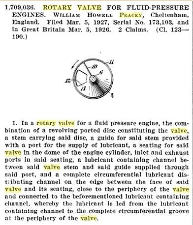
THE PEACEY ROTARY VALVE: 1926
The Reverend William Howell Peacey of Cheltenham was a remarkable man. Having built a successful steam car with a flash boiler and a 3-cylinder rotary-valve (of course!) single-acting steam engine under the floorboards, he went on to develop a rotary-valve IC engine. Although Peacey was a clergyman and not a trained engineer, this apparently worked well until the boiler blew up at a pressure of 1,750 PSI; flash boilers hold little water so all concerned survived. There are more details here.
 |
| Left: The Peacey rotary valve: 1926
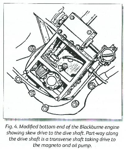
The Peacy valve consisted of a vertical funnel-shaped rotor, with segments cut out to act as valve ports. It had some similarities to the later Aspin rotary valve. The valve was fitted to a Blackburne engine. After the WW1 Blackburne became a major supplier of engines to motor cycle manufacturers, including the Cotton company.
Peacey obtained US patent 1,709,036 in March 1926.
Source: �Cotton Pickins� the journal of the Cotton Owners & Enthusiasts Club, Sept 2020. Used by permission.
|
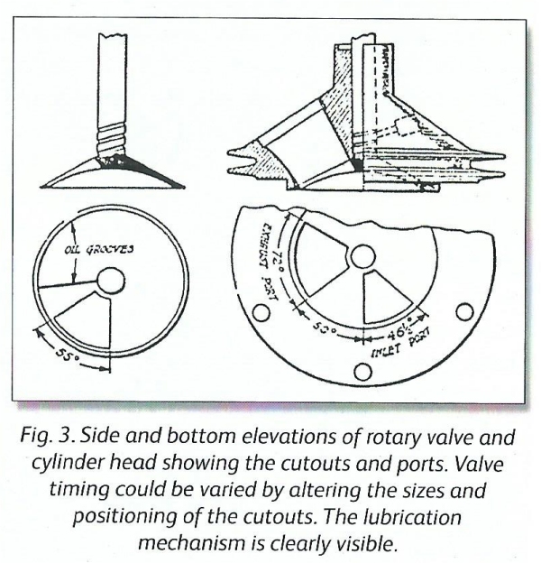 |
| Left: The Peacey rotary valve: 1926
Oil was fed from the oil pump to the rotating valve spindle, which had a spiral groove on its lower part which pumped oil down between the valve cone and the cylinder head. The valvegear and its drivetrain were fully enclosed to prevent loss of oil.
Source: �Cotton Pickins� the journal of the Cotton Owners & Enthusiasts Club, Sept 2020. Used by permission.
|
 |
| Left: The Peacey rotary valve: 1926
The Peacey valve was driven by a pair of gears mounted in a flat case. The vertical shaft was driven from the crankshaft by a helical gear.
Source: �Cotton Pickins� the journal of the Cotton Owners & Enthusiasts Club, Sept 2020. Used by permission.
|
 |
| Left: The Peacey rotary valve: 1926
This shows the vertical shaft driven from the crankshaft by a helical gear. The transverse shaft comes out of the rectangular box at the top, which probably contained another pair of helical gears.
Source: �Cotton Pickins� the journal of the Cotton Owners & Enthusiasts Club, Sept 2020. Used by permission.
|
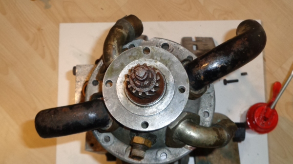 |
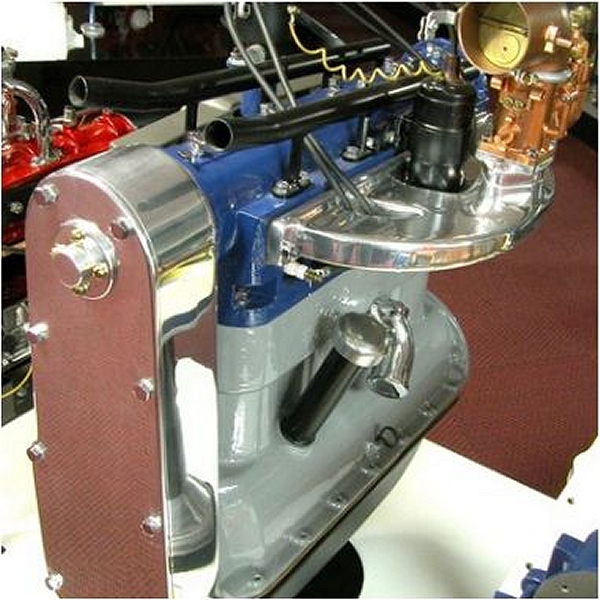
| Left: The Peacey rotary valve: 1926
This shows the top of a Peacey valve engine, with the driving gear in the centre.
|
 |
| Left: The Peacey rotary valve: 1926
Summary of US patent 1,709,036 for the Peacey valve.
|
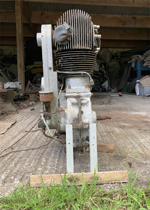 |
| Left: The Peacey rotary valve: 1926
Peacey also did a rotary valve conversion of a Sunbeam engine, shown here, but this time the rotary valve was mounted at right-angles to the piston and the combustion chamber (which resembles 1/4 of an orange) is to one side of the head.
I am informed that "...it did thousands of miles on tests at the hands of Bob Peacey- we have his log books! The castings are of a very high standard for a one-off prototype."
Peacey seems to have had much better results than other rotary-valve exponents, and it is a question why his designs were not developed further.
Image kindly provided by the Cotton Owners & Enthusiasts Club.
|
THE SCHEEL ROTARY VALVE
 |
| Left: The Scheel rotary valve: 1928
The rotary valve head on this engine was invented by the American Herbert Scheel who at one time worked for Louis Chevrolet.The head had a horizontal valve with ports in it, very much like the Minerva valve just above. There is more information at the Museum Of American Speed website. Ford Model-A engine were used with the head replaced by the rotary valve version.
The cover on the left holds the chain drive to the horizontal valve. Its shape suggests that the two sprockets were the same size and the valve therefore rotated at crankshaft speed.
|
 |
| Left: The Scheel US patent, granted 1928
Here the horizontal valve is driven by a shaft and bevel gears; they are of equal size so this confirms that the valve rotated at crankshaft speed.
|
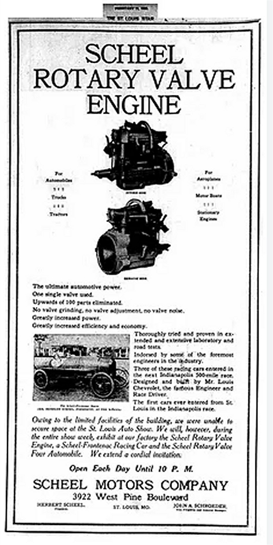 |
| Left: Scheel advert: date unknown
I hope the text in the ad is just about readable. "Greatly increased efficiency and economy" are just two of the claims.
|
THE CANNONBALL BAKER ROTARY VALVE
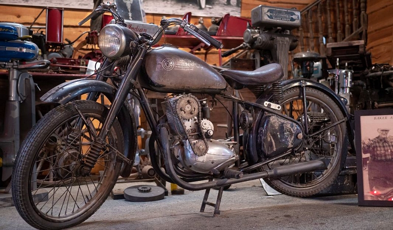 |
| Left: The Cannonball Baker rotary valve engine: 1933
The legendary Cannonball Baker, racer and promotor, took this Czechoslovakian CZ motorcycle and modified the engine with his own design of rotary-valve top end. Baker claimed he got 180 miles per gallon during an economy test in a cross-country trip in 1941, when he was 60 years old.
No technical details of the rotary valve have bern found so far.
There is some more info on Baker's life here.
There is some info here about an engine with two rotary valves that may have been associated with Baker.
|
THE ERNST ROTARY VALVE: 1940s?
This rotary valve engine was apparently invented by Dr Ernst, (floreat 1900-1950?) a Larchmont dentist who lived at 149 Beach Avenue. The invention was found on the website of the Larchmont Historical Society.
I know it says don't reproduce, (thank you Dr Malthus) but the site gives no way to contact its owners, and indeed does not even tell you where Larchmont is.
But it is now confirmed the inventor was Otto Ernst, a dental surgeon from Larchmont, New York. He obtained the following patents for his invention (all with the same content): US1083812, CA152393, GB191321530, DE282325 and FR463107. They are all from the early 1910s, therefore contemporary with the Mead valve, which was installed in the Speedwell car. The springs visible on the top of the engine in the photograph are indeed part of the valve-sealing mechanism.
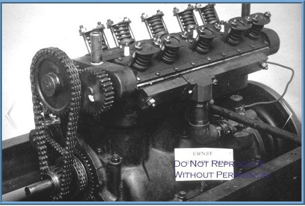 |
| Left: The Ernst rotary valve engine: date is guesswork
It may have been designed by a dentist, but this looks like a pretty workmanlike job to me.
There are clearly two rotary valves running horizontally across the top of the cylinder block, coupled with a pair of spur gears and driven from the crankshaft by the vertical chain. Looking at the sprocket sizes, it appears that the valves rotated at half crankshaft speed. The five pairs of springs visible on the top of the engine in the photograph are part of the valve-sealing mechanism. It seems unlikely this is five-cylinder engine; four is much more probable.
The other horizontal chain probably drove the water-pump and magneto.
|
THE ASPIN ROTARY VALVE SYSTEM: 1933-1977
This rotary valve concept by Frank Aspin has a conical vertical valve rotating above the cylinder. The Aspin is probably the best-known rotary valve after the Cross, but it seems to have suffered significantly more technical difficulties.
 |
| Left: One version of the Aspin rotary valve. Note the conical thrust bearing C, intended to absorb the upward thrust of high pressures in the cylinder. This version has no rotor cooling.
Aspin's first experimental engine was a 250cc machine, based on a Rudge 250cc motorcycle engine. It was built in 1933. Aspin claimed that it produced 18 bhp at 7500 rpm, 31 bhp at 10,000 rpm, and was capable of a maximum speed of 14,000 rpm. It used a 14:1 compression ratio, implying great resistance to pre-ignition, given the low-octane petrol of the time, and this was ascribed to the absence of a hot exhaust poppet valve in the cylinder.
All these figures were startlingly high for the engine technology of the time, and it appears that they were greeted with some disbelief. A recurring theme in the Aspin story is impressive claims for performance, without backing from independent testing.
An Aspin modified Velocette 350cc engine was tested without much success by the Velocette factory in Birmingham in 1936.
By 1939 Aspin had decide it was necessary to liquid-cool the valve rotor to prevent distortion. This change did not greatly reduce the heating problems but it did require the spark-plug to be moved away from its central location, and it was placed at the side of the cylinder, placed so the rotating valve uncovered it at the right time for ignition. The valve rotor at this point was made of case-hardened nickel steel, rotating in an aluminium-bronze housing. Performance was once again claimed to be exceptionally good, but lubrication problems persisted, and the engine required careful warming up since heavy-footed use when cold would be certain to cause seizure of the valve rotor.
|
At some point Aspin tried a variable-speed drive to the rotor, ie changing speed during the combustion cycle but still in sync with the crankshaft; the idea being that the rotor would be moving relatively slowly during the high-friction parts of the cycle. It does not appear to have been a success, and would certainly have added complications to what is (in principle) a beautifully simple design.
In 1944 the magazine Autocar tested a family car with a four-cylinder Aspin engine.
In the 1960's an Aspin-converted 8.6 litre Leyland lorry engine was used to power a bus operated by The Northern Ireland bus company. At this point Aspin was using a lead-beryllium coating on the rotors to reduce friction. The bus ran successfully for an unknown period, recorded only as "many thousands of miles" until oil consumption abruptly climbed as the special coating on the valve rotors wore off. No further testing was done so the results cannot have been too impressive.
Aspin developed his rotary valve concept over more than thirty years, and there is not space here to trace the detailed evolution of his ideas. In essence, Aspin could build an engine with high oil consumption and good reliability, or with normal oil use but having a distressing tendency for the rotary valves to seize up solid. He never resolved this problem, and many others also failed.
Aspin's last rotary valve patent was taken out in 1977 (US 4033317) and I believe he died shortly afterwards.
There is a very fine site on the Aspin valve and its engines here.
THE FROEDE ROTARY VALVE: 1950s.
Walter Froede was the head of the German company NSU's motorcycle racing program; at the time, NSU was the largest builder of motorcycles in the world.
 |
| Left: Froede rotary valve in a 125cc racing motorcycle engine. Valve rotor coloured pink.
The detailed design of the rotary valve was done by Felix Wankel, building on his valve designs for the Daimler-Benz�s DB601, a 33.4-liter V-12 for military aircraft, and later the Junkers KM8 torpedo engine. The engine is tilted over to the left, and the piston is shown at TDC. The rotary valve was driven at a constant 1/4 of crankshaft speed. Although initially successful in racing, it was not repeated, probably due to the demise of NSU.
|
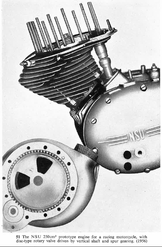 |
| Left: Froede rotary valve in a 250cc racing motorcycle engine: 1956
In 1936 Felix Wankel joined the Deutschen Versuchsanstalt F�r Luftfahrt (German Experimental Institute for Aviation), designing rotary valves for Daimler-Benz�s DB601, a 33.4-liter (2,020 cu. in.) V-12 aeroengine, and later the Junkers KM8 torpedo engine. See the next section for more on Wankel and rotary valves.
|
Later NSU introduced the famous Wankel rotary IC engine, but its poor reliability and short service life finished off the company and NSU was absorbed by Audi.
FELIX WANKEL AND ROTARY VALVES: 1935-1950s.
Felix Wankel, the originator of the famous rotary engine, was involved from 1930 to 1945 in the development of a rotary disc valves for use in aircraft and torpedo engines. His primary expertise was in the difficult business of sealing. During this time he worked at BMW, DVL, Daimler-Benz, Lilienthal and Junker Aircraft.
Various sources state that he was involved in developing the "Daimler-Benz DB601 V-12 rotary disk valve aircraft engine" but other sources say that this engine had four conventional poppet valves. This mystery currently remains unresolved. He certainly worked on the Junkers Jumo KM8 torpedo engine, which had to fit into a cylindrical casing that had no room for conventional valvegear. The short working life of a torpedo engine meant that rapid wear of the rotary valve disc was not an issue.
 |
| Left: Cross-section of a Junkers Jumo KM8 disc-valve engine, enclosed in its torpedo casing.
The disc valve is visible on the right side of the engine, just above the piston.
The KM8 engine had eight liquid-cooled cylinders of 90mm bore by 85mm, stroke arranged as a V-8 with a 90deg angle. The total swept volume was 4.34 litres and the compression ratio was 6.6 to 1. Output was 275 HP at 3650 rpm. It ran on a mixture of petrol, oxygen, and its own exhaust gas- the latter presumably to dilute the oxygen to a manageable content.
There is more info on the KM8 engine here. It was a`Closed Cycle' (Kreislauf cucle) engine using petrol and oxygen diluted with exhaust gas for propulsion of submarines and torpedoes; the exhaust was cooled by sea-water before mixing with the petrol and oxygen. When pressure built up in the system some of the gas was released through a relief valve.
A production order for 100 engines was issued towards the end of WW2 but was never completed. A prototype was examined by British and American intelligence engineers, who concluded it was "a progressive trend in automotive development." It would appear they were wrong.
|
|
Above: Longitudinal section through one cylinder bank of a Junkers Jumo KM8 disc-valve engine.
The disc valves are fitted between upper and lower cylinder heads. They had teeth on their periphery, and formed two gear trains without the need for idlers or extra gearwheels. The train of valve discs was driven by bevel gears from the crankshaft, with splined connections to allow valve timing to be altered.
|
In 1951 NSU became interested in Wankel's rotary engine project, and he joined them. It seems very likely he was involved in the design of the Froede rotary valve shown above.
THE MELLORS ROTARY VALVE SYSTEM: 1940s.
 |
| Left: The Mellors maltese-cross valve drive system.
The Mellors rotary valve system had two conical valves, one for inlet and one for exhaust. They moved not continuously but in 90-degree steps, driven by a maltese-cross mechanism. When stationary the valves were pressed against their housing by helical springs and so were cooled. Just before each movement they were lifted a few thou from their seatings by a face cam. The valve was thus able to turn freely, and then was released back to its rest position when it stopped.
The use of the maltese-cross or Geneva mechanism was first suggested by Mueller in a 1914 rotary valve patent.
It appears that the valve drive shaft at the bottom of this picture rotates once per cycle, ie at half crankshaft speed. The maltese cross mechanism would have been subjected to some severe accelerations, and I am not too sure how well this would have worked at high rpm.
|
 |
| Left: The Mellors valves in cross-section.
Note the hinged sections and the two little levers at the top. This may have been a method of applying sealing forces to the valves, but I suspect it might have been a misinterpretation of the two levers that lifted the valves when they were due to turn.
Ted Ambrose Mellors was an international motor cycle racer; he became European Champion in 1938. He designed and patented his rotary valve system in the early 1940's, during WW2. See Patent 559830, March 1944.
He died in 1946:
see Ted Mellors Biographical Notes (External site)
|
 |
| Left: The Mellors rotary valve system fitted to a 250cc New Imperial engine.
The two bolted-down covers on the side of the cylinder head show the valve locations.
|
 |
| Left: Mellors' prototype rotary valve engine today.
A close-up of the maltese-cross mechanism. The two maltese crosses marked A are driven by pins on opposite sides of the central disc B.
Image kindly provided by John Wood.
|
THE NORTON ROTARY VALVE ENGINE: 1950s
Joe Craig, Norton development engineer, spent two and a half years working on a horizontal rotary valve proposed by Laurie Bond. (The originator of the Bond three-wheeler) The valve design closely followed Cross technology.
There were the usual problems with lubrication, sealing, and plug fouling, and the resulting engine, called the Manx, (a reference to TT racing) was less powerful than the standard version. Definitely not a success.
 |
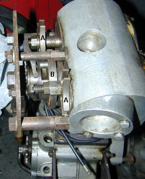
| Left: The Norton Rotary cylinder head fitted to a Manx Norton motorcycle engine
The Manx engine was based on a square-500 design. The cylindrical valve at the top is driven by bevel gears from a vertical shaft, which is driven from another vertical shaft via two small pinions. The second vertical shaft is driven by bevel gears from the crankshaft. The mystery of why two vertical shafts were used has been solved by Jean-Fran�ois Depau, who points out that in his book "Built For Speed", John Griffith writes: "As the head is wider than that of a "Manx" unit, the vertical shaft of the bevel drive had to be stepped out to reach the end of the rotor. A virtue was made of this necessity by installing a gear-type oil pump at the "step", so that the drive went in on one shaft of the pump and out on the other."
This book was published by Temple Press, second impression in 1965. John Griffith was a journalist in the 1950's, writing for Motor Cycling magazine. His specialty was road testing the motorcycles of the day, but he had a special interest in historic racing motorcycles.
Image kindly provided by John Wood.
|
The Manx engine began its life with a 35 BHP output, which was developed to 47 BHP. There were problems with valve seizure due to uneven expansion of the head assembly. In 1954 Norton policy towards racing changed and the project was shelved.
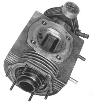 |
| Left: The Norton Rotary cylinder head seen from the underneath
The bearing for the vertical drive shaft can be seen at top right.
Image kindly provided by John Wood.
|
THE DUNSTAN ROTARY VALVE: 1957
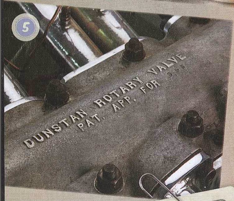 |
| Left: The Dunstan rotary valve
The Dunstan rotary valve was introduced by South Australian engineer David Dunstan in 1957. It was a horizontal valve running across the tops of the cylinder-heads, and was applied to a Holden grey six-cylinder engine, which in unmodified form gave only 60hp at 3800rpm, from its 2163 cc.
This picture shows the top of the valve housing.
Image from Wheels 1957
|
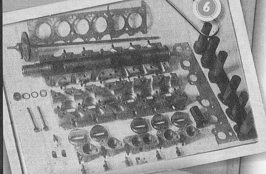 |
| Left: The Dunstan rotary valve
This shows the parts used to modify the standard engine. The rotary valve lies across the page in the upper half of the picture.
Image from Wheels 1957
|
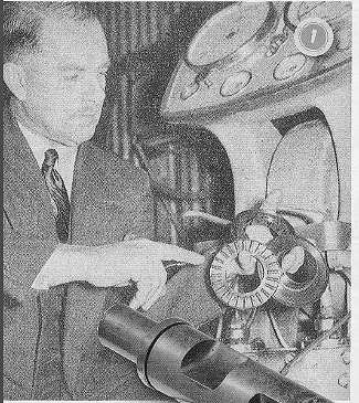 |
| Left: The Dunstan rotary valve
David Dunstan displays the parts of his rotary valve. The valve itself is bottom right; it looks like a substantial piece of metal.
The machine with dials next to him is probably a dynamometer for engine-testing.
Dunstan died in 1958 and interest in the idea appears to have then faded.
Image from Wheels 1957
|
THE ZIMMERMAN ROTARY VALVE: 1959
 |
| Left: The Zimmerman rotary valve: 1959
In the mid-fifties Merritt Zimmerman developed a horizontal valve, that in 1959 was applied to a 250cc V-twin engine that reliably produced 39.5 bhp at 9000 rpm, giving
158 bhp/litre, rather impressive at a time when poppet valve engines struggled to reach 100 bhp/litre. The engine was installed in a motorcycle that raced regularly in US enduros and scrambles. Zimmerman took out two patents on the valve but resisted efforts to persuade him to the engine for production, for reasons currently unknow.
The diagram is taken from Zimmerman's first patent and is a section through a four-cylinder engine. The horizontal rotary valve 52 was rotated by skew helical gears on a a horizontal shaft 108 running the length of the engine, which was driven from the crankshaft by what appears to be a toothed belt. (Toothed belts were first used in a car engine in 1954, so no anachronism here) This shaft ran at crankshaft speed. The item 38 is the oil filler pipe. The valves were manufactured in 1.5% chrome cast iron with a nitrided surface, and supported by ball bearings at each end.
Zimmerman's 1972 patent runs to 21 pages and I'm not going to pretend I've read it all yet. In short, what Zimmerman claimed was a lubrication metering system that adapted itself to the load on the engine, and some form of self-adjustment in the valve so it would fit properly with low friction at various temperatures. Judging by the results, these ideas were effective.
Zimmerman also took out US patent 5,052,349 in 1991 so clearly his work on rotary valves was no passing interest.
Thanks to the Cotton Owners & Enthusiasts Club for drawing this valve to my attention.
Source: US patent 3,871,340 of 1972.
Assigned to Tetrahedron Associates Incorporated.
|
 |
| Left: The Zimmerman rotary valve: 1959
This shows the horizontal shaft 108 driven from the front of the engine. (the flywheel is at the left) Since pulleys 16 and 100 are the same size, the shaft 108 clearly turns at crankshaft speed, but since the helical drive gears to the valves seem to be in a 1:2 ratio, the rotary valves turn at half crankshaft speed.
The lubrication control system is at 119, on top of the engine.
There is more info on Zimmerman here.
|
THE ALPHA ROTARY VALVE ENGINE: 1962
In the early Sixties, Alpha Bearings of Dudley in the West Midlands produced an engine in which the flywheel acted as a rotary valve. All I know about it comes from the very informative website here so I will send you straight there.
It is heartening to report that Alpha Bearings are still very much in business.
THE QUEENS UNIVERSITY BELFAST (QUB) ROTARY VALVE: 1967
The QUB 250cc twin cylinder two-stroke rotary valve engine was devised by Gordon Blair, M Johnston and others at Queens University Belfast in June 1967.
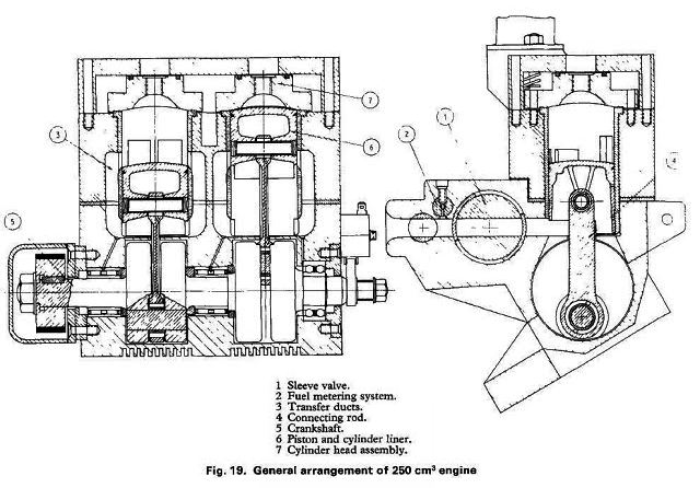 |
| Left: The The QUB two-stroke rotary valve engine: 1967
The inlet valve was cylindrical, admitting the charge to the underneath of the piston, from where it was transferred to the top of the piston and ignited; there were conventional exhaust ports. The valve was therefore not exposed to high pressure on the power stroke.
A 250cc water cooled twin cylinder engine with the new valve was designed and built from scratch, and first road tested on a motorcycle in 1969.
Dynamometer tests showed a very steep power increase above 9000 rpm with an abrupt drop above 11000 rpm. Maximum power was 45 BHP.
|
 |
| Left: The The QUB two-stroke rotary valve engine: 1967
This drawing gives details of the rotary inlet valve.
The motorcycle was raced twice in 1969, but failed both times due to small-end bearing failure.
More information can be found at the Yorkshire Ferret,
Thanks to Paul Burke for bringing this engine to my attention.
|
THE DEANE ROTARY VALVE: 1971
The Deane spherical valve was devised by William Ronald Deane, Harry Bishop and Charles Beard of Victoria, Australia.
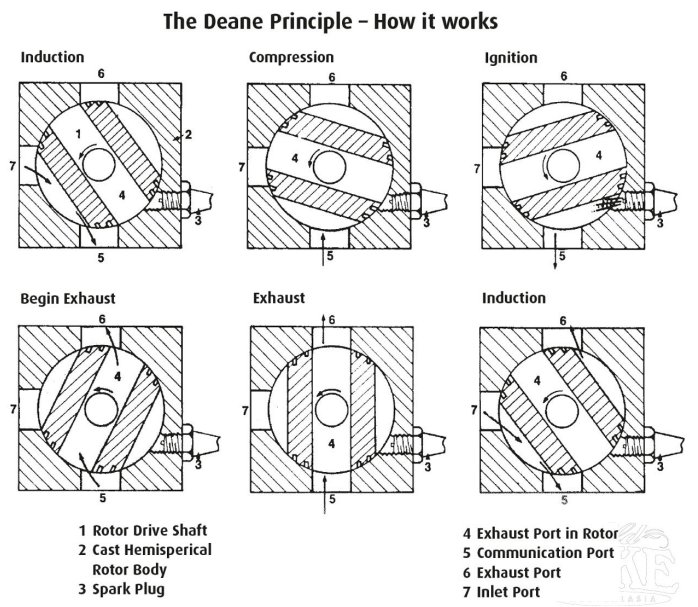 |
| Left: The Deane spherical rotary valve: how it works
The Deane Rotary valve used a spherical steel rotor fitted with piston-style sealing rings. It turned at one-quarter crankshaft speed in the cylinder head.
Despite considerable publicity, the project was unable to attract financial backing.
Deane was issued US patent 3,730,161 filed 28 May 1971
|
THE ESSO-CROSS ROTARY VALVE ENGINE: 1975
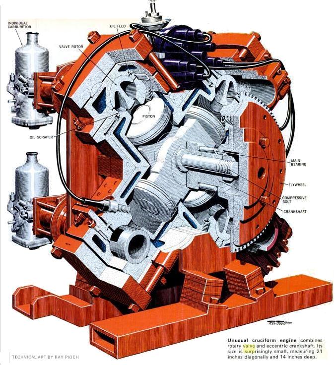 |
| Left: The Esso-Cross rotary valve engine from the exhaust side
The Esso-Cross rotary valve engine was a joint project between Esso and the Cross Manufacturing Company of Bath. This was after the death of Roland Cross in 1970. Its two radical feature were the rotary valves and an eccentric crank system much the same as that patented by Charles Parsons (of turbine fame) for his epicyclic steam engine in 1877.
The stated engine capacity was 1606 cc (98 cu in) from which it was hope to ultimately get 145 HP. The compression ratio was a high 10.5:1, designed to exploit the absence of exhaust-valve hotspots given by the Cross rotary valves.
The same reaction-bridge arrangement invented by Roland Cross around 1935 was used to control the loading on the rotary valves.
Popular Science July 1975
|
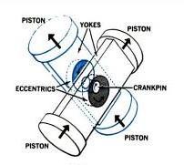 |
| Left: The Esso-Cross eccentric crank system for the rotary valve engine
This arrangement eliminates the connecting rods of a conventional engine. It was also supposed to reduce the number of heavily-loaded bearings from 13 to 5, and eliminate side-forces on the pistons.
Popular Science July 1975
|
 |
| Left: The Esso-Cross rotary valve engine
How it moved.
Animation by Bill Todd. Another stunning bit of work.
|
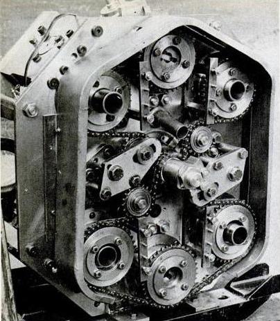 |
| Left: The Esso-Cross rotary valve engine from the induction side. Each stub pipe leads to the centre of a rotary valve, and had an SU carburettor attached
The convoluted path of the chain drive for the four rotary valves can be seen. I think there are two separate chains, each driving two valves.
Popular Science July 1975
|
At the time of the Popular Science report in July 1975 the engine was said to have run for 75 hours at the Esso Research Centre in Abingdon, developing 69 HP at 5500 rpm. Quite a long way short of the hoped-for 145 HP.
It is absolutely usual for wildly optimistic claims to be made for new IC engine concepts. One of many is that the new engine will be able to successfully run on low-octane fuel using a high compression-ratio. Given the earlier successes of the Cross rotary, this claim seems more plausible here than is usually the case. Strangely, this intriguing project appears to have dropped completely out of sight, despite the claim by Stephen Baker (an Esso research engineer working on the project) that it had aroused "considerable commercial interest". The Popular Science article of 1975 is the only reference known to Google.
THE LOTUS ROTARY VALVE TWO-STROKE ENGINE: 1991.
In the early 1990's several manufacturers were investigating supercharged two-stroke engines as the way forward. Since a two-stroke has one firing stroke per crankshaft revolution as opposed to one every other revolution, the power-to-weight ratio is potentially much better. The engineering challenges involved in making an engine that can compete with the conventional four-stroke are, however, severe.
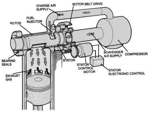 |
| Left: The Lotus two-stroke Rotary valve project: 1991
This two-stroke engine was of the "uniflow" type, with exhaust ports uncovered as the piston moves down.
Because there is no dedicated exhaust stroke, scavenge air is blown in to clear the exhaust gases out of the cylinder by an external compressor, and then the fuel/air mixture is admitted.
The rotary bearing was of the Cross or horizontal type, rotated by a toothed belt at crankshaft speed as this is a two-stroke. By rotating the stator inside the valve, the inlet timing and the relative duration of scavenge air and mixture admission phases could be altered.
It was commented at the time that the uniflow operation should avoid the overheating and lubrication problems of other rotary valves which handled exhaust gases as well as induction. However, as far as I can see the rotary valve here is still subjected to the full combustion pressures, and I wonder how this was tackled.
|
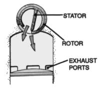 |
| Left: End view of the Lotus two-stroke Rotary valve.
When the Lotus project was reported in the press, it was said to be in "the early stages" of development, and no performance figures were given. I can find no further reference to it anywhere, and it is far from certain that even a prototype engine was built.
Interest in two-stroke engines fell away as emission standards became tighter in the 1990's.
|
UNIDENTIFIED ROTARY VALVE ENGINE: 19??
Photographs of this four-cylinder rotary valve engine were sent to me by David Ziegler, a researcher for the Smith Collection, of The Museum of American Speed located in Lincoln, Nebraska.
We would be very glad if someone could indentify it or provide any information at all.
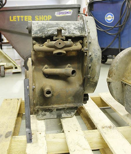 |
| Left: Unidentified rotary valve engine
The valve cover on top and the camshaft drive cover at the right do not seem to match the rest of the engine. This is likely to be an experimental conversion.
There appears to be a standard inlet/exhaust manifold arrangement, except that the upper flange (presumed to be the inlet) seems to have too small an aperture for normal operation. The upper dual pipe is probably the inlet for water-cooling.
The general opinion of my correspondents is that the lower 'pipe' on the side of the crankcase is an engine mounting.
|
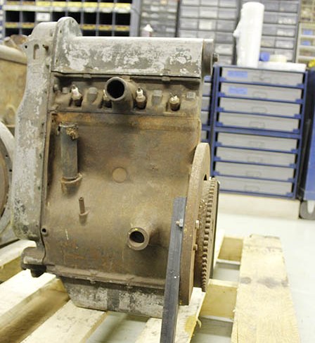 |
| Left: Unidentified rotary valve engine
The engine from the other side, showing four spark plugs, the one on the right being broken.
The pipe between the spark plugs is probably the outlet for water-cooling. The lower 'pipe' is probably the corresponding engine mounting.
|
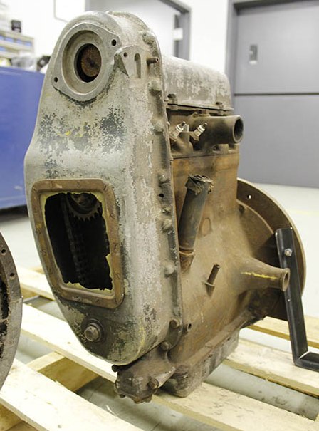 |
| Left: Unidentified rotary valve engine
The camshaft drive cover shows a chain drive inside, though puzzlingly this does not extend up to the camshaft. There is presumably a second chain drive inside that is not visible.
The drive cover appears to have been once fitted with with a celluloid window to allow observation of the working parts, but only the edges of it remain.
|
THE COATES ROTARY VALVE SYSTEM
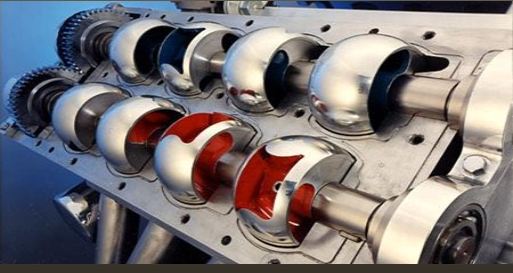 |
| Left: Coates rotary valve engine
Here is apparently a contemporary development: The Coates Spherical Rotary Valve System; one of the Coates patents is in the table below. Judging by the website alone, they seem to be serious about what they're doing.
The Coates website claims that the use of this valve "has permitted elimination of both oil lubrication and cooling water flow in the upper portion of the cylinder head." which seems somewhat out of line with the experiences of Aspin and Cross. It is probably significant that the Coates valve, which, if the website is to be believed works, is horizontal like that of Cross rather than vertical like the less successful Aspin.
|
But... it seems it was a scam. If you read through this rather long document (Thanks to Will Poundstone for providing that link) it emerges that there were a whole load of financial shenanigans and Mr Coates ended up in jail when he was arrested for mail fraud. However, there were certainly prototypes built, which were tested by Harley-Davidson. In November 1991, Harley notified Coates that it was discontinuing testing of the Coates prototype engines because of mechanical durability problems; no surprise there. Coates also lied about his engines meeting EPA emissions standards.
The Coates website still exists and was apparently updated in 2022.
OTHER ROTARY VALVE SYSTEMS
These are rotary valves about which little is known.
The Brown rotary valve was developed by J & E Brown of Wednesbury, Staffordshire. It first appeared in 1938, fitted to a modified 490cc Norton motorcycle. It emerged again after WW2, and was highly praised in The Motor Cycle for Oct 16, 1947. A conversion kit for overhead cam Nortons was planned but apparently never appeared, and the Brown Valve faded from view.
John Anelay introduced a spherical rotary valve system in 1955. So far no more information has been found on this.
The Museum of American Speed located in Lincoln, Nebraska, has two rotary-valve engines on display; a Reynolds and a Scheel rotary valve head.
The Crosley Rotary-Valve Midget engine.Crosley was a USA manufacturer of sub-compact cars and should not be confused with Crossley.
A Ford Model-A conversion by Scheel Motors Corp.
ROTARY VALVE SYSTEMS NOW
Rotary valve systems have not disappeared; it seems that nothing technological ever does.
A contemporary concept is the PatRoVa rotary valve. Like the Cross design it balances out the forces acting on the rotating valve.
 |
| Left: Bishop Innovation rotary valve: from the patent
From 2002 to 2004 the Australian developer Bishop Innovation and Mercedes-Ilmor were testing a Formula-1 V10 engine with rotary valves. Bishop Innovations' patent for the rotary valve engine was bought by BRV Pty Ltd, owned by Tony Wallis, one of the valves original designers. There are some biographical info on Tony Wallis here.
The technology uses a horizontal valve on top of the cylinder and is very similar to the Cross rotary valve above, one of the few that had some success. It is not at present clear what was new and patentable.
From European patent EP 1,792,058 B1 granted 29 Dec 2010. See also US patent 7,584,741 Sept 2009.
|
It is clear that we have not yet heard the last of rotary valves in IC engines.
ROTATING CYLINDER ENGINES
A related technology is the rotating-cylinder-valve engine, in which not just a valve assembly, but the whole cylinder rotates. This has been introduced for 4-stroke operation by RCV Engines Ltd, a UK-based company.
One advantage claimed is that the absence of a hot exhaust valve in the cylinder gives greater freedom from detonation, allowing the engine to be run on kerosene (JP8) with a high compression ratio and hence good efficiency.
 |
| Left: Cross-section of an RCV model engine.
The version shown here is for model aeroplane propulsion. The cylinder (green) is geared to the crankshaft through bevel gears (purple) carrying a valve port around with it. The propellor is fastened to the head of the cylinder, and this axial format gives a small cross-sectional area and consequently reduced aerodynamic drag. Note that the finned cylinder jacket and the exhaust system do not rotate.
The concept is being extended to one-cylinder engines for scooters, mopeds and motorcycles. For more info see RCV Engines.
|
ROTARY VALVE PATENTS.
Some British rotary valve patents. (not a complete list) Dates are when the patent was granted.
Patent NoDateNameValve type
136 334Dec 1919MusuresHorizontal rotary valve
151 994 Apr 1922 TebaldiHorizontal rotary valve
158 269 Jan 1921 DennisonHorizontal rotary valve
168 841 Sept 1921 FrancisHorizontal rotary valve
171 822 Dec 1921 StonerVertical rotary valve
173 877 Jan 1922 AcherHorizontal rotary valve
| .
| 246 687Feb 1926CrossHorizontal rotary valveThe first Cross patent
259 400Oct 1926CrossHorizontal rotary valve
268 937 April 1927 PeaceyVertical rotary valve
373 660June 1932CrossHorizontal
408 756April 1934CrossHorizontal
411 010May 1934CrossHorizontal
448 368June 1936CrossHorizontal rotary valve
463 412Mar 1937AspinVertical rotary valveThe first Aspin patent
559 830Mar 1944MellorsHorizontal
570 286Jun 1945AspinVertical
570 354July 1945AspinVertical
| .
| 872 216July 1961AspinVertical
| | | | | | | | | | | | | | | | | | | | | | | | | | | | | | | | | | | | | | | | | | | | | | | | | | | | | | | | | | | | | | | | | | | | | | | | | | | | | |
Here is a small and so far very incomplete list of rotary valve patents in the USA. Dates are when the patent was granted.
Patent NoDateNameValve type
908 656 Sept 1907 Frayer & HowardHorizontal transverse
908 657 Aug 1908 FrayerExplosive engine
921 264 May 1909 MeadHorizontal longitudinal
924 382 June 1909 ReynoldsVertical rotary valve
983 328 Feb 1911 VallilleeVertical
1 007 040 Oct 1911 MeadHorizontal longitudinal
1 154 647 Sept 1915 MeadHorizontal longitudinal
1 098 679 1914 MuellerVertical
1 159 482 1915 EnglishVertical
1 427 726 Aug 1922 EchardVertical rotary valve
1 539 041 May 1925 CrawfordVertical rotary valve
1 718 755 June 1929 CharterGas engine
2 129 024 Sept 1938 ReynoldsHorizontal longitudinal
2 283 594 May 1942AspinVertical rotary valveAs British patent 463 412
Some more recent US patents:
4 008 694 Feb 1977 MonnHorizontal rotary valve
4 404 934 Sep 1983 Asaka et alHorizontal rotary valve
4 658 776 Apr 1987 Coman
4 773 364 Sep 1988 HansenVertical rotary valve
4 788 945 Dec 1988 Negre
4 852 532 Aug 1989 BishopHorizontal rotary valve
4 944 261 Jul 1990 CoatesHorizontal rotary valve
5 000 136 Mar 1991 HansenVertical rotary valve
5 052 349 Oct 1991 Buelna
5 490 485 Feb 1996 Kutlucinar
|
| | | | | | | | | | | | | | | | | | | | | | | | | | | | | | | | | | | | | | | | | | | | | | | | | | | | | | | | | | | | | | | | | | | | | | | | | | | | | | | | | | | | | | | | | | | | | | | | | |