Gallery opened June 2008
Updated: 15 Feb 2022
More on Perfetti engine added: 1927
CONTENTS OF THIS PAGE


CONTENTS OF THIS PAGE
CONTENTS OF THIS PAGE
Axial Internal-Combustion Engines
|
An axial or barrel engine has multiple cylinders arranged around and parallel to a central shaft, like the chambers in the cylinder of a revolver. The piston thrust is usually converted to rotary motion by a swashplate or Z-crank mechanism. The claimed advantages for this engine format were low frontal area (important for powering aeroplanes) very good balance and great compactness. On the downside there were major problems with the swashplate or wobble-plate mechanisms, and access for maintenance was poor. The axial IC engine was an obvious development of the Axial Steam Engine. No axial IC engines have achieved any sustained success.
AXIAL ENGINE TECHNOLOGY
Wobble-plates and swash-plates are not the same thing:
 | Left: A wobble plate motor wobbling.
|
 | Left: A swash plate motor swashing.
|
A variation on the swashplate engine is the cam-plate engine, in which the plate is not a flat surface, but is given a sinusoidal contour. The pistons can now be made to move back and forth twice or more during one rotation of the main shaft, giving more firing strokes and potentially increasing the power output of an engine of a given size. See The Dynacam Engine below.
There is a whole gallery of non-axial cam engines just around the corner from here.
An engine expert speaks:
"Such cylinder arrangements have serious disadvantages with regard to accessibility and mounting structure, which would make them undesirable for most services even if a reliable mechanism could be developed. There is no likelihood of such engines becoming important competitors to the conventional types."
(Quote from The Internal-Combustion Engine in Theory and Practice by Charles Fayette Taylor, 2nd edition, pub MIT press 1985. This book is a standard work on the subject of IC engines)
While I hesitate to argue with Charles Taylor, I don't see his point about accessibility and mounting structures. Accessibility for adjustments with the engine running would of course be a challenge with one of the rotating-barrel types; doing a compression test would be a most interesting procedure. The doubt about the reliability of wobble & swash mechanisms is more telling. However, I don't doubt that if we really needed axial engines with long-term reliability for some reason, the problem could be solved.
There have been some unconventional engines which have used wobble-plates but are in different galleries of the Museum because they have even more unusual features. One example is: The Selwood-Hughes Engine which had toroidal cylinders.
THE SMALLBONE AXIAL ENGINE: 1906
 | Left: The Smallbone axial engine patent: US 821,546 of 22nd May 1906.
|
![]()
THE LAMPLOUGH AXIAL ENGINE: 1910
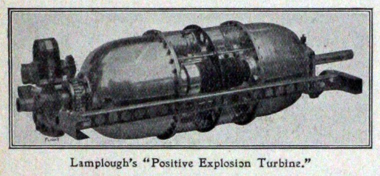
This engine is rather obscure. The image below appears on the Net as "Lamplough's rotary engine" without any mention of the word "axial". It is only a rotary engine in that the engine and propellor rotate while the crankshaft is fixed; it has no relation to Wankel-type rotary engines. The trail is confused by a conventional radial 6-cylinder rotary aero engine that was built and exhibited by Lamplough; that suggests that this was also intended to be an aero engine.
 | Left: The Lamplough Axial Engine: 1910
|
This image is clearly a drawing. I have seen a very similiar image entitled "Positive explosion turbine" (!) but that too looked very much like a pen-and-wash drawing. Currently, it is not clear if the engine was actually built or not.
Lamplough & Son Ltd were based at the Albany Works, at Willesden Junction in North-West London; the company was founded in 1899.
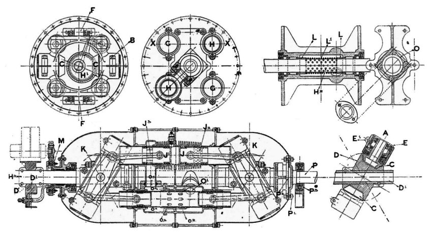 | Left: The Lamplough Axial Engine: 1910
|
These sections show a four-cylinder two-stroke engine with eight opposed pistons, but it seems that two of the four cylinders (those without fins) are pumping cylinders that compress the charge for the power cylinders. This does not sound as if it would give a good power/weight ratio. A gear-driven magneto is fitted at the left end of the engine; since this does not appear to rotate with the main body of the engine, it is not clear how the electricity was routed to the spark plugs whizzing round.
Having only the drawing above to go on, I consulted the redoubtable Bill Todd, and he said:
"It's not a wobbler, it's a swashplate/cam engine. At each end of the cylinders, two pairs of con-rods push on a rocker pivoting about the axis F. Each rocker has tapered rollers (C) running in a flattened V groove cam/swashplate (D) at its end of a fixed hollow shaft. The whole cylinder assembly rotates, breathing through the hollow shaft."
Note the eccentric visible in the top left drawing. I though this might be someting to do with ensuring accurate swashing, (see the Redrup engines for more on this) but Bill says:
"The eccentric controls the pumping cylinders input valve timing (but may also control scavenge timing - hard to see from the drawing)"
 | Left: The Lamplough Axial Engine animated
|
Bill has decoded the valve operation as follows:
The fuel/air mix enters throught the central shaft from the left. (magneto end) where it escapes into the central distribution chamber.
As the power pistons close together on a compression stroke, the pumping pistons are retracting, drawing the mix into the pump cylinder via the ports in the lower right input chamber. The pumping cylinder (at the bottom) is divided in two parts connected only by ports in the pump-cylinder sleeve
On the power stroke, the pump compresses the mix, via left side ports, into the lower left transfer chamber and up to the cylinders transfer ring, ready for the left piston to open the transfer ports.
At the bottom of the power stroke the main transfer ports (upper left) and exhaust ports open and allow the fresh mix to scavenge the cylinder through the exhaust holes (upper right).
 | Left: The Lamplough Axial Engine animated
|
There is a sketchy Wikipedia page for Frederick Lamplough who appears to be the relevant man; it says he was British. Bill did some more searching, and so did I. Fred Lamplough was a prolific inventor with 30+ patents. His first patent, for an automatic drain valve, (US 515,294) was filed in January 1893, when he was living in New York. He had apparently moved back to England from the USA by 1899, as he filed a UK patent in Feb 1899. His last US patent (US 1,765,167) was filed in 1926; it related to 'Conversion Of Heavy Hydrocarbon Oils Into Light Hydrocarbon Oils Or Spirits'. There are more biographical details in Grace's Guide.
The patent most relevant to this engine appears to be US 979,971 of 1910 'Two-cycle internal-combustion motor' which describes a 2-stroke engine with separate pumping and power cylinders, though it is not an axial engine. US 859,501. of 1907 describes what is essentially a Diesel injector.
Bill concludes:
"Interesting to see his patents are referenced in some patents filed in 2010. He seems to have been an important contributor to the pumped two stroke engine."
 | Left: The Lamplough Axial Engine: 1910
|
![]()
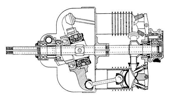
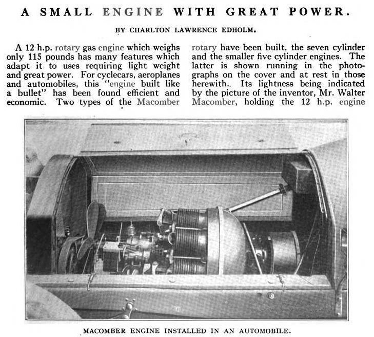
THE MACOMBER AXIAL ENGINE: 1911
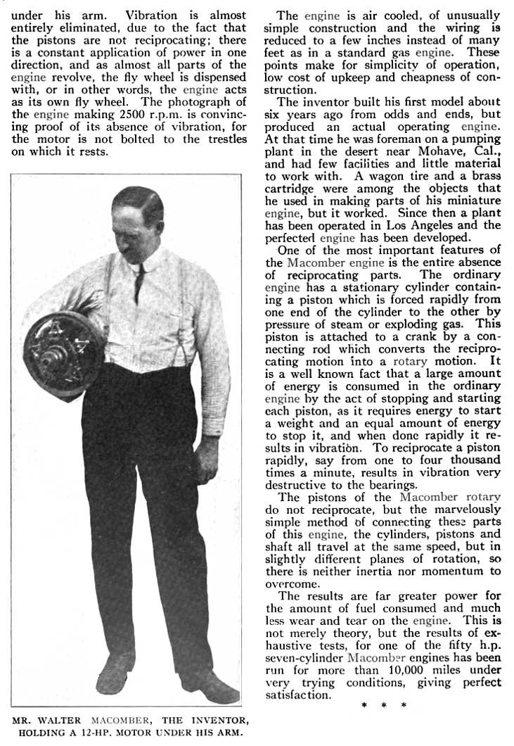
The first IC axial engine the indefatigable staff of the Museum have tracked down that was definitely constructed and put into use are the five and seven-cylinder rotating-barrel wobble-plate engines designed by Walter G Macomber. The ball joints between the connecting rods and the plate make it clear that it is of the wobble-plate persuasion.
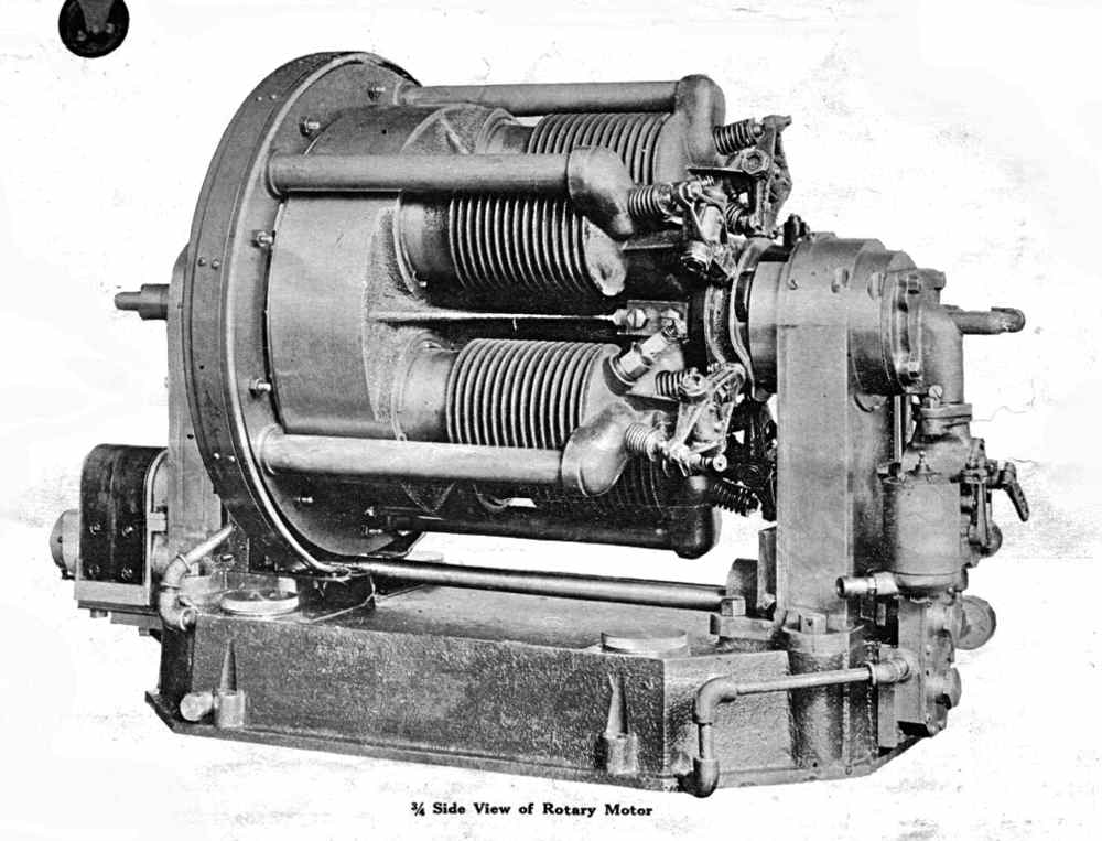
 | Left: The Macomber Axial Engine: 1911.
|
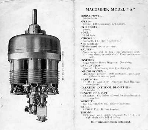 | Left: The Macomber Axial Engine: (7-cylinder version) publicity material.
|
This list raises one or two questions. "Positive lubrication" implies pumped pressure lubrication, and it is not easy to see how that could be done without a pump having some moving parts. It is also difficult to see how fuel injection would have worked, if this means an injector on the cylinder head or in the inlet port.
How many engines were built and sold is currently unknown. It is recorded that it made at least one successful flight in May 1911, in a plane piloted by Charles F Walsh.
 | Left: Patent drawing of the Macomber Axial Engine: 1912.
|
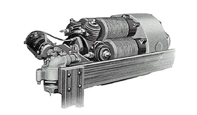
 | Left: Macomber Axial Engine (7-cylinder) for the Macomber-Eagle car: 1915
|
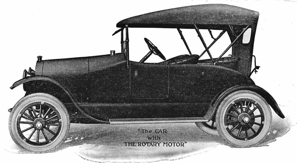 | Left: The Eagle-Macomber car: 1915
|
 | Left: Macomber 5-cylinder engine in the Eagle-Macomber cycle-car: 1912
|
 | Left: Macomber 5-cylinder engine in the Eagle-Macomber cycle-car: 1912
|
It is a bit of a mystery why axial rotary engines should have been so popular in the early days of flying; The Trebert engine of 1912 and The Nedoma-Najder of 1924 are two more examples on this page. The snags include the difficulty of getting the fuel/air mixture to the whirling cylinders, the impossibility of using anything but stub exhausts, and all sorts of potential problems with centrifugal force affecting the valvegear, the lubrication, and so on.
On the upside you got a very heavy flywheel for free (ie with no added weight) but then there was already a big propellor attached to the output shaft, and I would have thought that gave quite a bit of flywheel action.
More conventional rotaries such as the well-known Gnome engine were, for a short time, successful at powering early aircraft. Having cylinders arranged radially, they had the advantage of air-cooling of the whirling cylinders; this was an advantage an axial rotary did not enjoy. But... the heavy rotating mass gave rise to interesting gyroscopic effects. It gave the Sopwith Camel remarkable turning power- in one direction. This, in the hands of an expert, could be very useful in combat. To an inexperienced pilot it could all too easily be lethal. The gyroscopic problems, coupled with breathing restrictions due to the convoluted air-fuel delivery path, meant that rotaries fell out of use after the First World War.
THE TREBERT AXIAL ENGINE: 1912
This remarkable rotary axial aeroplane engine was produced by Henry L.F. Trebert, who had an engine works in Rochester, NY.
 | Left: The Trebert Axial Engine: 1912
|
The air-cooled engine had six axial cast-iron cylinders and a central rotary valve, which communicated with the small finned cylinders at the end of the main cylinders, from which the spark plugs protrude. The stationary valve had a one inlet and one outlet port on its periphery, connecting to the radial cylinders as they passed. Since the ports have to open every two revs of the crank
the cylinders have to revolve at half engine speed.
Cylinder bore was 3.75in, stroke 4.25in, and the total displacement 4521cc (282 in3) It was rated at 60 HP. It used a Panhard carburetor and Mea magnetos. The weight (fully equipped) was 230lb, giving 3.83 lb/HP. Overall length was 22in, and outside diameter 15.5in.
The Trebert company also produced a barrel-type marine engine.
 | Left: The Trebert Axial Engine animated
|
 | Left: The Trebert Axial Engine patent
|
 | Left: The Trebert Axial Engine animated
|
THE GNOME AXIAL ENGINE: 1911
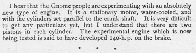 | Left: Rumours of a Gnome Axial Engine: 1911
|
The Gnome company of France are best-known for making the Gnome rotary engines, in which the cylinders went round but the crankshaft stayed still; such designs had inherent problems that caused them to disappear after WW1.
I have found no other reference anywhere to such an engine. Perhaps the rumour was groundless.
THE STATAX AXIAL ENGINE: 1913
The first IC axial engine in Europe (sometimes erroneously stated to be the first ever) was a on-off prototype built by Statax-Motor of Zurich, Switzerland in 1913; it was designed by Dr. F.J.M. Hansen who apparently had links with the German air force in WW1. The engine was confiscated after the war by the British authorities and ended up in the Science Museum in London, though it is not, I believe, currently on display.
In 1914 Statax moved to London and planned a series of rotary engines, but apparently only a 5 cylinder version giving 40 HP was ever made. It was put into a Caudron G.II aeroplane to compete in the British 1914 Aerial Derby but was withdrawn. Dr Hansen produced an all-aluminum version of the engine in 1922, but it is not clear if it was produced in any quantity. Much improved versions were introduced by Statax's German division in 1929, giving 42 HP in a sleeve valve version called the 29B.
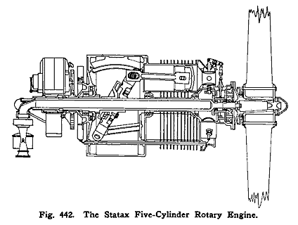 | Left: The Statax Axial Engine.
Original source: The Airplane Engine Encyclopedia by Glen D Angle, published in 1921 by Otterbein Press. |
THE SALMSON AXIAL ENGINE: 1913
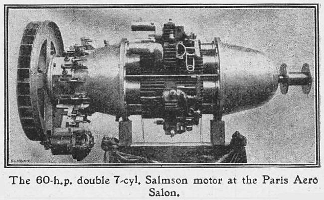 | Left: Salmson Axial Engine: 1911
|
The propellor shaft is at the right, and at the left end of the engine there appears to be some sort of cooling fan for a radiator. Just to the right of the fan is a series of levers of uncertain function- they look to be too far away from the cylinders to be valves. Below this is an auxiliary that is probably a dynamo, driven from the periphery of the fan.
Flight gave the following specs:
Nominal HP60
Bore (mm)75
Stroke (mm)260
RPM1300
Weight (kg)100
Price (Francs)10,000 |
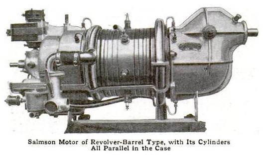 | Left: Salmson Axial Engine: 1913
|
The casing at right with the offset shaft emerging presumably contained reduction gearing so the engine could turn faster than the propellor. This seems rather advanced for the time.
The Salmson company survived until 1951.
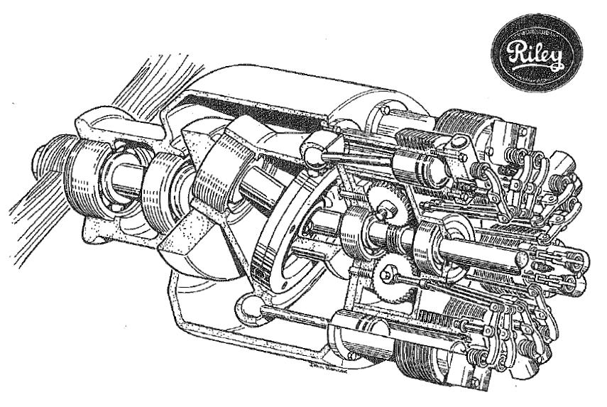
THE RILEY ENGINES: 1914
Percy Riley was one of the men behind the British Riley Motor Manufacturing Company. Riley also began manufacturing aeroplane engines, becoming a key supplier in Britain's buildup for World War I. Early aero engines were of the rotary type, such as the Gnome Monosoupape, in which the whole engine rotated about a stationary crankshaft. Riley thought he could reduce the heavy whirling mass that was just one disadvantage of the rotary aero-engine, and became interested in axial engines.
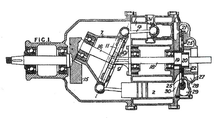 | Left: Riley Axial Engine patent, 1914
|
Cutaway drawing and information from “Riley- Beyond the Blue Diamond” by David G Styles. This book is currently out of print but may be reprinted if sufficient demand exists. Email davidstyles208@yahoo.com to express your interest.
The version shown above is apparently the liquid-cooled two-stroke version; this was later intended for powering early tanks. Only four of the cylinders produced power, the other four were pumping cylinders for the 2-stroke cycle. This would more than outweight any advantage in specific power that could be gained by 2-stroke operation. The output shaft is on the left. At right is a rotary disc valve that controlled the transfer of the fuel/air mixture.
 | |
Above: Cutaway drawing of the Riley 4-stroke axial engine, 1914
|
In a later design (Patent 11933 of August 1915) Riley reduced the number of cylinders to seven, which gave a much better firing order, and introduced compressed-air starting.
 | Left: Percy Riley: date unknown
|
![]()
THE MICHELL AXIAL SWASHPLATE ENGINE: 1920
 | Left: The Australian Michell swashplate engine: 1927. Eight-cylinder static barrel swashplate-plate type
|
 | Left: Michell slipper pad
|
Michell used his bearing and his knowledge of lubrication to design several swashplate engines. Between the piston and the swashplate is a hemispherical thrust block with a raised and rounded leading edge which helps the oil film get between the thrust block and the swashplate. Michell took out US patent No 1,409,057 for his engine in 1922. This has been mis-referenced as 1,404,057 in other patents referring to it, and as a result it took some tracking down.
 | Left: A 5-cylinder 5-piston Michell engine meant for road vehicles: 1921
|
 | Left: A 5-cylinder 5-piston Michell engine meant for road vehicles: 1921
|
 | Left: Longitudinal section of an 8-cylinder 4-piston Michell engine meant for road vehicles: 1927
|
 | Left: Section through piston and valves of 8-cylinder 4-piston Michell engine for road vehicles: 1927
|
 |
| Left: Longitudinal section in front of swashplate, and end view, of 8-cylinder 4-piston Michell engine for road vehicles: 1927
|
 | Left: Longitudinal section of a 300HP 8-cylinder 4-piston Michell engine for driving gas compressors: 1927
|
 | Left: Michell engine in the Powerhouse Museum, Sydney, Australia: 1927
|
 | Left: Michell engine in the Powerhouse Museum, Sydney, Australia engine: 1927
|
 | Left: Michell engine in the Powerhouse Museum, Sydney, Australia engine: 1927
|
 | Left: A single-ended Michell engine: 192?
|
The stalk-type piston P is cast integral with the cylindrical yoke which slides in segmental guides concentric with the cylinder bore, the swashplate rim running through the annular gap between the inner and outer guides, as shown in the small drawing below. The swashplate S and the clutch member C (the presence of which seems to indicate that this engine was intended for road use) are attached to a flange on the main shaft. This shaft turns in two self-aligning ball-bearings; there is also a thrust bearing T to take the force of the power strokes on the swashplate. The valves are of the conventional overhead poppet type, actuated by rockers and ball-ended push-rods driven by the face cam F, which is driven at one quarter engine speed through idler pinion and an internal gear ring. The cylinder head at left contains concentric induction and exhaust manifolds at I and E. The auxiliaries were driven by means of spiral bevel gear, with a shaft passing radially between two of the cylinders.
 | Left: Single-ended Michell engine piston guides: 192?
|
As with several other engines in this gallery, an odd number of cylinders are used because this gives a uniform firing interval; five cylinders gives an interval of 144 degrees. (720/5)
![]()
THE ALMEN A-4 WOBBLE-PLATE ENGINE: 1921
 | Left: The Almen aero engine: 1921
|
 | Left: The Almen aero engine
|
 | Left: The internals of the Almen engine
|
| The vital statistics of the Almen engine |
 | Left: The Almen engine patent: US1255973 of Feb 12, 1918
The patent was assigned to the Almen-Crosby Motors Company. |
 | Left: The wobbling of the Almen engine animated by Bill Todd
|
![]()
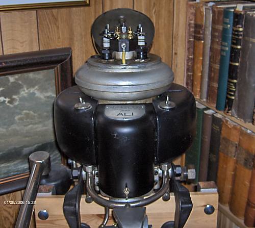
THE ALI OUTBOARD ENGINE: 1922
The ALI axial outboard engine was designed by Arvid Lind in Sweden, and reached the market in 1922. It was a popular choice for racing competition, but its general use was limited as it was expensive to produce, costing twice as much as an ordinary engine. The factory in Stockholm was closed when the inventor died in 1932.
Lars Eimar owns an Ali engine bearing the number 308, so presumably at least this number were built, making it one of the more sucessful axial engines.
  | Left: The Ali Engine: 1922
Original source: Zeitschrift Des Vereines Deutscher Ingenieure (The magazine of the Association of German Engineers) p1405, 1925 |
 | Left: The Ali Engine in plan view : 1922
Original source: Zeitschrift Des Vereines Deutscher Ingenieure (The magazine of the Association of German Engineers) p1405, 1925 |
 | Left: The Ali Engine: 1922
|

|
| ||
|
![]()
THE ROLLS-ROYCE AXIAL ENGINE: 1923
 | Left: The Rolls-Royce engine: 1923
|
![]()
THE WISHON ROTARY-VALVE AXIAL ENGINE: 1923
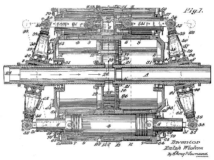 | Left: The Wishon engine patent: 1923
|
 | Left: The Wishon engine rotary-valve gear train
|
![]()
THE LAAGE AXIAL CAM ENGINE: 1923
 | Left: The Laage axial cam aero engine: 1923
Original source: Zeitschrift Des Vereines Deutscher Ingenieure (The magazine of the Association of German Engineers) p1405, 1925 |
![]()
THE NEDOMA-NAJDER ENGINE: 1924
Above: The American Nedoma-Najder engine: 1924. Five-cylinder rotating barrel wobble-plate type
From NACA technical memorandum No 462, translation of Motorwagen Nov 20, 1927:
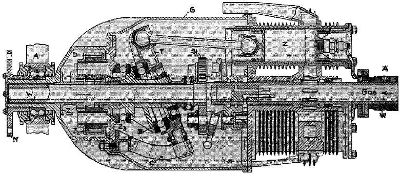
The stationary hollow shaft W rests on bearings A at each end. Around it revolve five cylinders Z, and the housing G carrying flange N for the propellor hub. The housing revolves on hollow shaft W on long bushings and in ball-bearing A at the propeller end. Gear Z1 is screwed to the front end of the revolving housing, and meshes with front planetary gear Z2, which transfers its motion to geared bushing Z3, which revolves at the same speed as housing G but in the opposite direction. The bushing B is keyed to Z3, on which the wobble plate T revolves on two ball bearings, being carried along by arm C which is fixed to housing G.
Due to the opposite motions of the bushing B and wobble plate T, a complete working cycle occurs in each cylinder for each revolution of the housing. The five aluminium cylinders were of 70mm diameter and 68mm stroke, with a single cast iron sleeve valve. The pistons were also of aluminium.
The sleeve valves were actuated by five shafts each carrying a helical groove and a gear meshing with a gear ring on the stationary hollow shaft. Two of these gears also operated two separate oil pumps. The inventor claimed an engine giving 40HP at 1400rpm would weigh 74kg, giving 1.83kg/HP.
The engine was intended for use in light aircraft, where its low frontal area would have reduced drag. It was the subject of United States Patent US1492215 (29 Apr 1924)
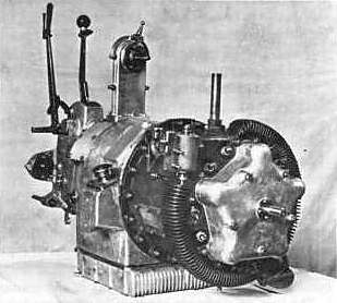
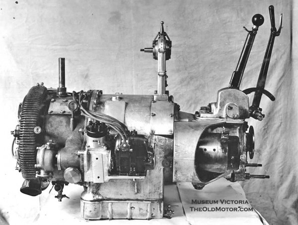
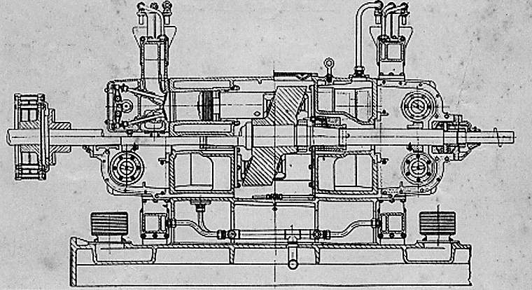
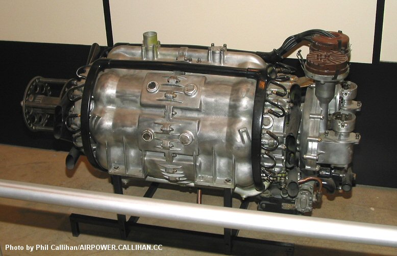
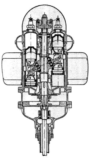
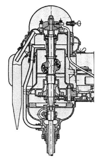
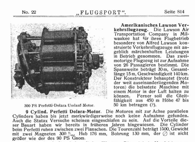
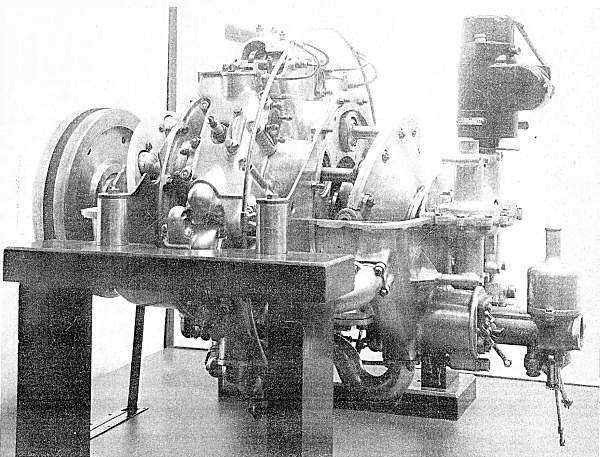
THE PERFETTI ENGINE
This engine was originally designed as an aero-engine, appearing in 1919. An article in Autocar for 1 June 1927 describes a plan to use the engine to power a car based on an unusual backbone chassis. It was a rotary engine, which at this period meant the whole engine rotated about a stationary central shaft; nothing to do with Wankels etc.
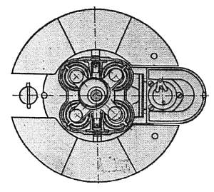
According to the French article, the wobble/swash plate A is geared to the plate B to which the air-cooled cylinders are attached, but that is not visible here. According to the caption, the teeth on plate B are engaged by the starter motor.
Source: Article from unidentified French journal
Many thanks to Reg Winstone for drawing this engine to my attention
This brief note tells us that the engine had nine cylinders and twin magnetos, and was claimed to give 300 HP, though weighing no more than a 90 HP Gnome engine.
The caption describes it as a 'circulation motor' which presumably means 'rotary engine'.
Source: Flugsport No 22, 29 October 1919, page 814
Source: INDEX OF AERONAUTICS of the INSTITUTE OF THE AERONAUTICAL SCIENCES, 30 Rockefeller Plaza, New York City: December 1939
This is a machine translation of the unidentified French journal referred to above, kindly provided by Reg Winstone:
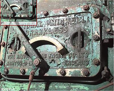
This engine, designed to be mounted on aircraft, can also be used in cars and boats. It is characterised by: a reduced size, a reduction in the number of parts and a very personal system for transforming the alternating rectilinear movement of the pistons into a continuous circular movement of the motor shaft. Its cylinders are arranged in a "revolver barrel" at equal distances from each other and around the motor shaft. This innovative assembly method on the Canton-Unné aviation engine was used in several other experiments, notably in the Mitchell engine and in the Van Caeyseele engine that we have recently described.
The transformation of the reciprocating motion of pistons into a continuous circular motion of a motor shaft or vice versa was used in the progressive speed changes of Jamey and De Lavaud as well as in several compressors or pumps for liquids or gases. In the Perfetti engine the cylinder group is itself made rotatable. Two plates, each mounted on a different shaft, are tangential and form a certain angle with each other. They each carry a bevel gear, so that the rotational movements of one of the plates are transmitted entirely to the second. One of the plates carries the cylinders, the other, connected by double ball-jointed connecting rods to the pistons, is the receiver and its shaft thus becomes the motor.
In the legend of figure IV, we give the decomposition of the forces generated by the explosion in one of the cylinders and the resulting application to determine the rotational movement of the transforming plate.
The advantages of grouping multiple cylinders in a "revolver barrel" are most attractive, as a large number of cylinders can be provided for without falling into the pitfalls of the "revolver barrel". The advantages of the multiple cylinder "revolver barrel" arrangement are most attractive, as a large number of cylinders can be provided without the pitfalls of expensive, complicated crankshafts and bulky crankcases being built. This saves weight and space, is beneficial to the design and prevents vibrations.
A very important feature of the Perfetti engine is the kinematic coupling of the motor and transformer plates, which rotate in the same direction and at equal angular speeds. The cylinders accompany the connecting rods, the ends of which have only very slight oscillations in their bearing surfaces, due to the slight inclinations they undergo during movement. It follows that the friction of the pistons in the cylinders must be greatly improved.
The length of the connecting rod is irrelevant, since the reactions that can arise from obliquity are practically negligible. This is another reason why the overall dimensions of the engine are favourably influenced. On the other hand, the use of long piston strokes is no longer hindered, which should lead to a better use of the expansion and an increase in efficiency.
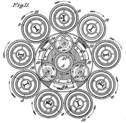
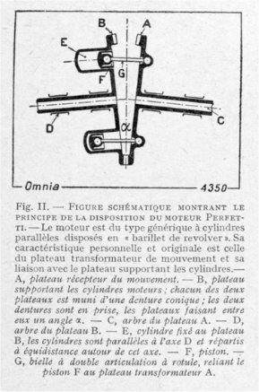
Fig. II.
The engine is of the generic type with parallel cylinders arranged in a "revolver barrel". Its personal and original characteristic is that of the motion transforming plate and its connection with the plate supporting the cylinders. - B, motor cylinder support plate; each of the two plates is provided with a conical toothing; the two toothings are in engagement, the plates making a fine angle a between them. - C, shaft of plate A. - D, shaft of plate B. - E, cylinder attached to plate B, the cylinders are parallel to the axis D and distributed equidistantly around this axis. - F, piston. - G, double ball joint connecting rod, connecting piston F to transformer plate A.
As it is possible to mount the cylinders in concentric rows around the motor shaft and to place two groups opposite each other in relation to the transformer plate, it is possible to achieve complete drive regularity and vibration-free operation. The rotating masses themselves form the flywheel, which also eliminates unnecessary dead weight.
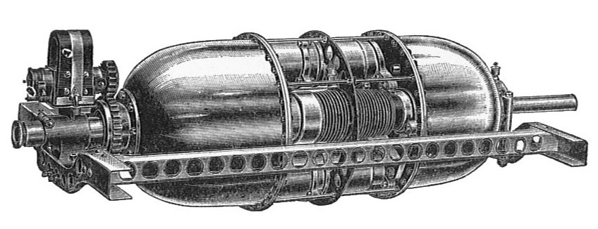
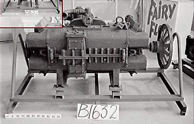
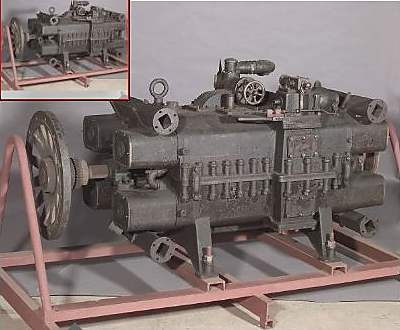
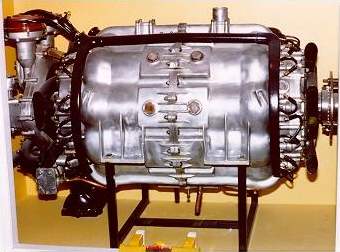
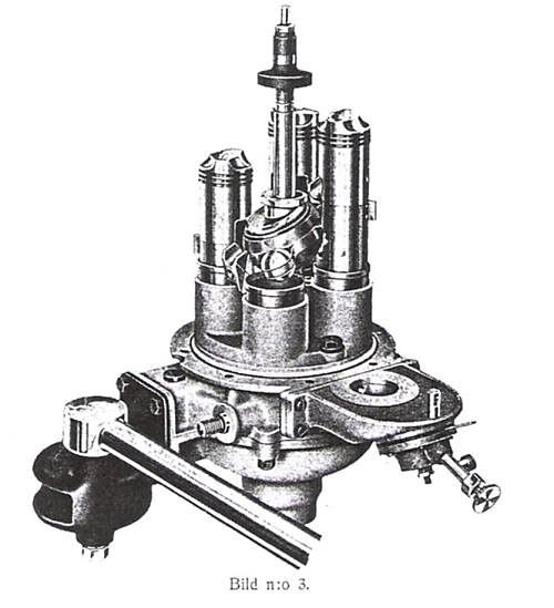
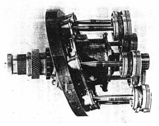
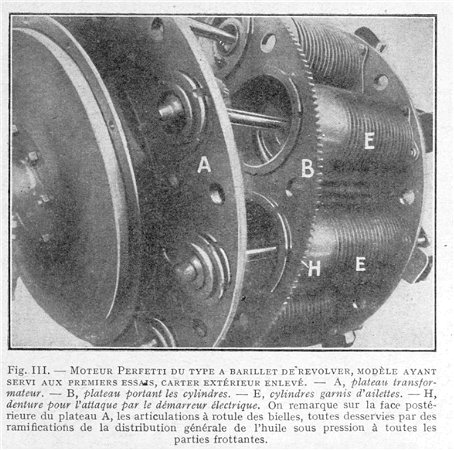
Fig. III. PERFETTI ENGINE OF THE REVOLVER BARREL TYPE, MODEL USED FOR THE FIRST TESTS, OUTER CASING REMOVED. - A, tralts/or-mator plate. - B, plate carrying the cylinders. - E, cylinders fitted with fins. - H, teeth for the electric starter. Note the ball joints of the connecting rods on the rear face of the A plate, all served by branches of the general distribution of oil under pressure to all the rubbing parts.
All the lubrication of the Perfetti engine is carried out under pressure even for cylinders and pistons. A special study has been made in order to reduce the action of centrifugal force on the pistons, to reduce the friction which results from it and the wear which would appear from it.
The cooling is by forced air circulation, which will be appreciated, both from the point of view of weight reduction and simplicity of construction.
It seems that this model has qualities that make it possible to envisage the use of the "revolver barrel" engine, for which the connection between pistons and plate has been the stumbling block until now. The experiments will be followed with attention."
Unfortunately this doesn't give much more information.
Note the tantalising reference to the Van Caeyseele engine in the first paragraph. Regrettably it appears to be unknown to Google.
CHARLES REDRUP & THE BRISTOL AXIAL ENGINE: 1934
Charles Benjamin Redrup (born in Wales in 1878) had a long association with axial IC engines. Before that he designed unconventional motor cycle egines, such as the rotary Barry engine, which was exhibited in 1904. Later he designed "Reactionless" rotary aircraft engines, in which the engine and crankshaft-propellor assemblies rotated in opposite directions to cancel out the troublesome gyroscopic effect. This did not live long or prosper because rotary engines had other inherent problems.
In the 1920s he produced wobble-plate axial engines, used to power a motor launch and a Crossley motorcar.
At some point Redrup also designed a cam-based axial engine. This demonstration model is in the Manchester Museum of Science and Industry. Regrettably it is in a glass case so you can't turn the handle.
Author's photograph
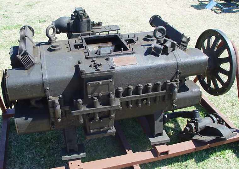
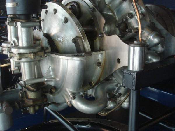
Charles Redrup was hired by the Bristol Tramways and Carriage Company in 1931 to design the engine below, and several variants were used in Bristol buses during the late 1930s. The engine went through several versions from RR1 to RR4. RR4/2 (ie engine number 2) gave 145 HP at 2900 rpm on the test bench.
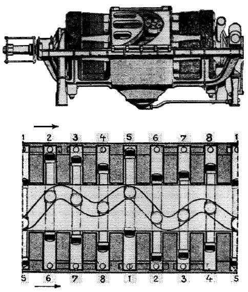
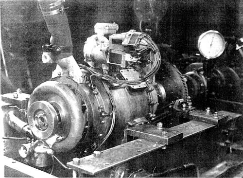
Above: The 7-litre Bristol axial engine of the mid-1930s, designed by Charles Redrup. Nine-cylinder static barrel wobble-plate type.
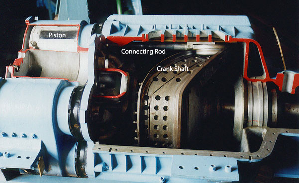
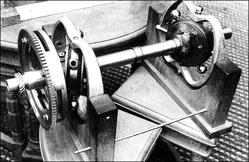
This engine was originally conceived as a power unit for buses and coaches, presumably because its compact format would allow it to be installed below the floor. Note the wobble-plate on the Z-shaped crankshaft, and one of the axial pistons and cylinders at the top. The engine had a single rotary valve to control induction and exhaust, which can be seen between the piston/cylinder and the cooling fan at the right. Some complication were required to make the wobble-plate move correctly, and the resulting vertical stabiliser arm can be seen just below the Z-crank.
A change of management at the Bristol Tramways company caused development to be stopped in October 1936.
I have not been able to determine which version of the engine this is.
Showing the crank-driven vertical stabiliser arm designed to give the correct kinematics.
During World War Two Redrup worked on top-secret armaments projects for the Avro Lancaster and other aircraft, including the hydraulic drive for the Vickers Type 464 bouncing bomb used in the Dam-Busters operation. He died in 1961.
THE SPAROST CAM ENGINE: 193?
This axial engine was developed in the 1930's. It had six enormous cylinders, driving a cam roller that fitted in between two sinusoidal ridges. In the photograph the cam roller can be seen at top centre,with its piston rod to the left of it. The Soviet Sparost was rated at 600 HP (how honestly is anyone's guess) and it was expected to reach 1200 HP by the late 1930's. As usual, the goal was a powerful engine with low frontal area.
The cutaway example shown here is in
Another view.
The cutaway example shown here is in
Because it is a five-cylinder engine, only one cylinder at the top is visible in section. I indicates the injector and S the spark-plug.
The wobble plate was stabilised with an attached bevel gear that meshed with another fixed to the main body of the engine, preventing the plate from rotating around the crankshaft. The bevel gear teeth are coloured blue in the drawing.
The valves were of the usual poppet type with horizontal stems, operated by rockers and pushrods, from a cam ring running at Ľ crankshaft speed. A valve can be seen just below the injector.
There is a Wikipedia page for the engine, but little information is given.
Pic from The Modern Diesel Engine, 5th edition, Iliffe & Sons Ltd
The capacity was 4 litres. Bore was 95 mm and stroke of 114 mm. The compression ratio was 6 to 1, and the claimed output was 70 BHP at 2400 rpm.
These engines were manufactured by Hulsemo NV at Arnhem in the Netherlands. They were exhibited in the Berlin and Amsterdam Shows in 1938. It has been claimed that these engines were in widespread use in commercial vehicles in Holland in the late 1930's, but confirmation of this is so far lacking.
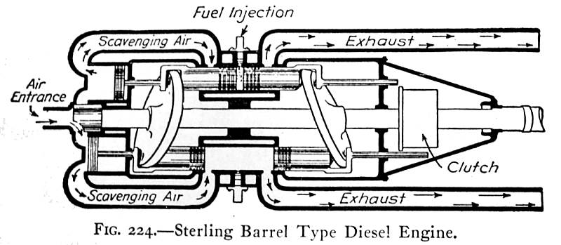
It appears that the air entrance is on the left, and the output shaft on the right, as in the diagram below.
This engine is unknown to Google, though you do get lots of hits for Stirling hot-air engines.
Source: Diesel Engines by von Bongart. Pub Van Nostrand, 1938
This swashplate engine was intended to run as a two-stroke Diesel. The scavenge air to blow the exhaust gases from the opposed power cylinders in the centre was compressed by the pistons on the left.
Notice the use of a rotary valve at the air intake.
The von Bongart book is clear that these engines were actually in production, in three sizes. One can only guess at how well they suceeded. I would have thought that Diesel operation would put a lot more stress on the swashplate mechanism, due to the high compression ratio and high cylinder pressures on ignition.
The Sterling Engine Company was based in Buffalo, NY. Most of its output appears to have been conventional engines, some being for marine use. Charles Fayette Taylor, in one edition (1985) of his famous textbook The Internal Combustion Engine in Theory & Practice mentions "Opposed-piston double-swashplate engines briefly put on the market by Sterling Engine Company, Buffalo, NY". That does not sound as if they did well.
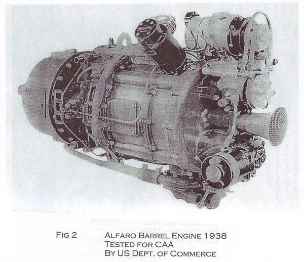
THE ALFARO AXIAL SWASHPLATE ENGINE: 1938
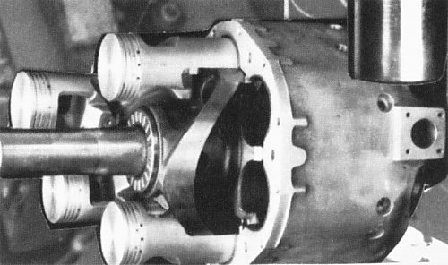
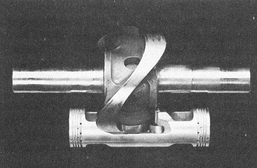
This is the only engine so far uncovered that has horizontally-opposed cylinders and a swash-plate at each end. This configuration doubles the number of rollers or bearing pads required compared with engines that have a single central swash-plate. Note that rollers rather than slipper-pads are used to contact the swashplates.
It was designed by the Spanish pilot Heraclio Alfaro. (who was knighted at the age of 18 by King Alfonso III for designing, building, and flying the first aeroplane in Spain) The engine was on test at MIT in 1934, where Alfaro was teaching. It had been built in Springfield, Mass, by the Indian Motorcycle Company.
According to Aerofiles, the engine had 4 cylinders and developed 155 HP from 167 cu in. (2737 cc)
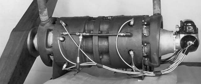
The engine had no valve system when operated as a two-stroke. (4-stroke operation was also envisaged) The exhaust ports were uncovered by the piston moving down, while the inlet ports, fed with compressed air from a geared blower, were likewise piston-controlled.
However, according to Wikipedia, the engine had a sleeve valve system based on a rotating cylinder head, an arrangement that never entered production on any engine. The engine was later developed further for use in the Doman helicopter by Stephen duPont, of whom more below. I have however been unable to find any evidence that it was actually flown in a Doman.
Alfaro took out US patent no 2,080,846. A photograph of the engine has now been discovered:
The trumpet air-intake at the right suggests that induction took place down the central shaft. The black thing pointing up at an angle is the distributor, while the other auxiliaries are not identified. Note the belt drive at top right.
The photo is from the book "A 1911 Spanish Pilot and MIT AeroEngineer and his 1938 AeroEngine – Upgraded for today by Stephen DuPont" ISBN 0-9777134-0-7. Stephen Dupont was the son of the president of the Indian Motorcycle Company, and worked as a student with Alfaro at MIT on this engine. Stephen is now 93 but still able to recount stories and discuss engines – he only recently quit flying his Pitts Specials at the age of 88 due to failing eyesight.
References:
Cullom, "The Alfaro Engine," Civil Aeronautical Authority Technical Development Report No. 4, Jan 1939. See also Auto. Ind., Dec. 1, 1939.
This engine has six double-ended pistons working in six cylinders, making it equivalent to a twelve-piston engine. All 12 combustion chambers are fired in a single revolution of the drive shaft. The sinusoidal cam can be seen, together with four of the six pistons and two empty cylinders.
The history of this engine is proving hard to track down, not least because access to the old dynacam.com website in internet archives is blocked; clearly this is part of The General Conspiracy.
However, the story so far: the engine appears to originate from a design by the Blazer brothers, who worked for Studebaker in 1916. They sold the rights to Karl Herrmann, Studebaker's head of engineering. He developed it over many years, taking out a patent in 1941; see US patent 2237989.
Note that the thickness of the cam (and it is everywhere very substantial) varies, appearing thinner where it is at a more oblique angle; this is because it runs between two rollers, in each piston, that are at a fixed spacing.
The engne received FAA Type Certificate E-293 on Dec 31, 1981.
By 1961 Herrmann was eighty years old, and sold everything to Dennis Palmer, one of his employees. At this point the Dyna-Cam name was attached to it. Eventually the engine was flown for seven hours in a Piper Arrow in 1987, but Dyna-Cam fell out with Piper in 1988, and things appear to have rested there until recently.
The assets of the Dyna-Cam Engine Corp were acquired by the Axial Vector Engine Corporation in 2006. The engine now has a 92-year history, which I should think must be unique.
Or is it? The mounting brackets look a bit flimsy, and it doesn't appear to be in a test cell.
Note the exhaust connections running upwards from each end of the engine.
You can see a promotional video for the Dynacam engine here. It claims that the engine was certified for both fixed-wing and helicopter use.
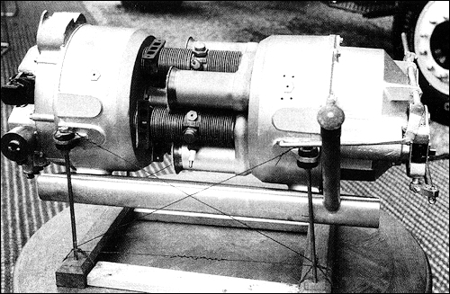
THE WOOLER AXIAL ENGINE: 1947
This six-cylinder static-barrel wobble-plate engine was designed by John Wooler (?-1955) who was better known as a motorcycle engine designer, for aircraft use. See here for more on John Wooler. (Wikipedia link)
This engine is similar to the Bristol axial engine, but has two wobble-plates, the angled discs that can be seen at each end. They were driven by 12 opposed pistons working in six cylinders. Some confusion about this engine has arisen because LJK Setright, in his book Some Unusual Engines, in a moment of uncharacteristic imprecision describes it as a swashplate engine; however it is a wobble-plate engine, not a swashplate engine.
Note SU carburettor at the extreme right. The tall dark thing top right is probably the distributor.
A view of the wobble-plate at the the carburettor end.
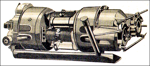
In 1948 Jules Brandt exhibited a white and black car at the Paris Salon; it was named "Reine 1950" (Queen of 1950) because its inventor planned to be selling it from 1950 onwards. Its main unusual features were a four-cylinder axial engine mounted between the front wheels and the absence of side doors; you entered the car by a front door, stepping over the engine. There was also a back door.
Here the engine is on a display stand. The 4-cylinder, 8-piston, two-stroke engine had a displacement of 935 cc, had fuel injection, and was claimed to produce 75HP at 4,500 rpm. If I have interpreted things correctly, this is a wobble-plate rather than a swash-plate engine.
The project was a failure.
Showing the two wobble-plates joined by a hollow central shaft. The helical gear at left is an auxiliary drive for the magneto and oil-pump. The large gear is presumably for the electric starter; there is no way to get a starting-handle to this thing. That was always a problem with transverse engines.
This is another display at the 1948 Paris salon.
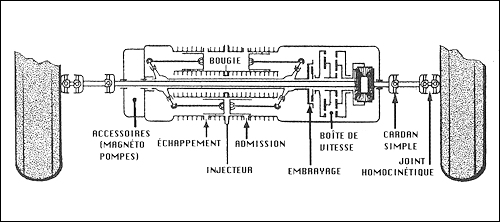
This diagram shows how the axial design allowed for an engine in the form of a narrow cylinder. There is what may have been a conventional clutch, followed by an epicyclic gearbox, which looks as if it might only give three speeds; there is no clue as to how reverse gear was implemented- if it was. To the right of that is the differential. Note that the drive to the left wheel has to pass back through the centre of the engine.
Bougie= spark plug
Can you mix up a simple Cardan joint with a homokinetic joint as shown? I have my doubts.
A drawing of the engine. (see first photo above)
Bill Todd suggests that this is a pumped 2-stroke engine. The pumping is done in the plain cylinders interleaved with the finned cylinders.
THE SEARLE ROTOCOM ENGINE: 1981
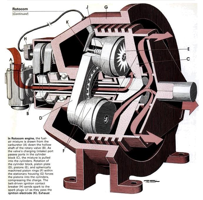
The Rotocom engine, invented by Russell Searle of Sunbury, England, was a three-cylinder four-stroke design. The pistons are rigidly fixed to a plate angled at 12 degrees to the central axis. The cylinder block is fixed to the central shaft, while the angled plate turns on a bearing, and causes the barrel-shaped pistons to move in and out of the cylinders. The barrel shape is necessary because the pistons do not slide straight in and out, but their axis moves in a small circle. Each piston has a sealing ring of Du Pont Vespel polymer, machined to a spherical surface. This was claimed to be gas-tight.
The central rotary valve is rotated at one and one-half engine speed by two belts (left of drawing) that also drive the ignition contact-breaker H.
Note the ignition electrode K that contacts each spark plug at the appropriate time. Remarkably, the spark plugs are mounted in the top of the piston rather than in the cylinder head; they don't look too accessible.
Lubrication was by adding oil to the petrol, which doesn't sound like a very reliable method to me. How was the oil supposed to reach some of those internal bearings?
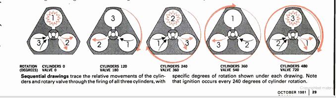
The cycle of operations.
The Searle Rotocom Engine is unknown to Google apart from the Popular Science article. Apparently it was never heard of again...
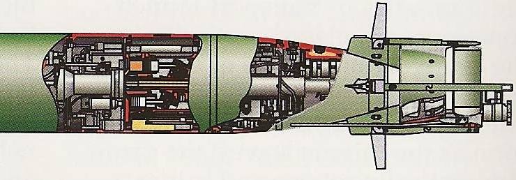
TORPEDO ENGINES
The cylindrical format of the axial engine is ideally suited to fitting in torpedos, and any lack of durability in the swashing/wobbling mechanism is not a problem if the operational life is measured in minutes.
THE US NAVY MARK 37 TORPEDO was designed as as an electrically powered homing torpedo; it was introduced into the US Navy in the 1950s. See Wikipedia. It went out of use from 1972 onwards, the remaining stock being converted to Otto fuel (see below) with the same engine as the Mark 46 torpedo described below, and sold to friendly nations. The conversion not only increased speed by over 40%, but increased endurance by more than 60%, more than doubling the MK 37 run range.
The engine is described as "a cam-piston" design which presumably means it uses a swashplate rather than a wobble-plate. The diagram is a bit short on detail but it looks as though the engine may use rotary valves.
The Otto fuel burns in a combustion chamber cooled by sea-water. It is not clear if water is sprayed into the hot gases to moderate their temperature and produce an added volume of steam, as is the practice in conventional "heater" torpedos.
The output power is delivered to the propellers by counter-rotating shafts; one driven by the cam and pistons and the other from the reacting housing of the engine which is free to rotate. These two shafts drive counter-rotating propellers. The engine exhaust gases, and perhaps the engine cooling water, exit via the hollow inner shaft. The rotating engine housing also drives the fuel pump and seawater pump by gearing, and apparently also powers the control-surface actuators.
The MK 46 cam-piston engine is essentially a constant torque output device, with the torque dependent on combustion pressure and back pressure. Fuel pump output pressure (combustion pressure) is controlled by an internal regulator that is referenced to sea pressure to maintain nearly constant shaft output torque as the sea pressure increases with depth. Constant vehicle speed is then maintained at all running depths.
THE US NAVY MARK 46 TORPEDO, designed to attack high-performance submarines, is powered by an axial IC engine. Variations of this torpedo are expected to remain in service until the year 2015, so axial engines are very much with us.
There are some details of the Mark 46 torpedo, though not much about the engine, here: Wikipedia (external link)
Details of the Mark 46 engine have, until now, proved impossible to find, and it is not unlikely that even looking for them will land the Museum staff in Guantamo Bay. However, this video claims to show the Mark 46 Torpedo axial engine mechanism in action:
Youtube video (external link) It is described as "Mk.46 ASW weapon's swashplate engine mechanism mock-up at US Naval Undersea Museum. Keyport, WA". Hard to see how many cylinders there are, but it looks like there might be nine.
The video is of poor quality but it looks as though the engine uses a wobbleplate rather than a swashplate format.
The wobbleplate engine can be seen to the left; to the left of that is a thing like a cotton-reel, presumably the heater/combustion chamber.
This is an unlabelled cut-away drawing of a torpedo produced by the "Sea Thermal Engineering Research and Design Institute" of St. Petersburg (Russia) that features a wobbleplate engine in the 300-1350 kW (heavy multi-purpose torpedo) or 60-200 kW (small torpedo) power output range. The original drawing is titled "Multipurpose depth homing torpedo", but unfortunately it is not currently clear which model it is or what fuel it uses, though it is probably of the kerosene-oxygen wet-heater type.
It's nothing to do with axial engines, but here is a torpedo engine with rotary valves.
THE AXIAL VECTOR ENGINE CORPORATION
There is an animation of their engine on Youtube (external link)
Axial have apparently acquired the assets of the Dyna-Cam Engine Corp; this news item appeared in the Portland Business Journal on Thursday, July 6, 2006:
"Dyna-Cam lawsuit settled.
Update Dec 2019: the domain is up for sale and the YouTube video is gone, so I guess that's it.
GYROSCOPE.COM
Update Dec 2019: The company still seems to be alive.
THE COAXE ENGINE COMPANY
Update Dec 2019: the website is now just one page with an email address, and the animation is gone. (404)
THE DUKE ENGINE
The Duke Engine is said to be already in an advanced state of development; it is claimed that multicylinder engines are operational and have been tested in Australasia and Europe, and are soon to be tested at Mahle Powertrain in the USA.
Update Dec 2019: The Duke website does not appear to have been updated since 2013...
BIBLIOGRAPHY
![]()
Left: The Perfetti engine: 1919
Left: The Perfetti engine: 1919
Left: The Perfetti engine: 1919
Left: The Perfetti engine: 1919
"The Perfetti engine without crankshaft.
![]()
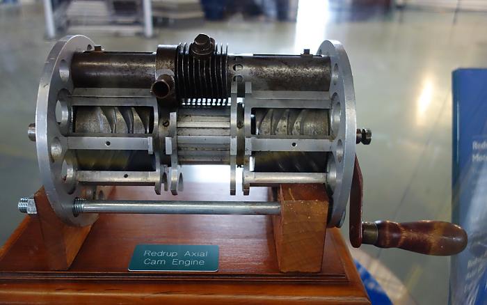
Left: The Redrup cam engine
From Some Unusual Engines by LJK Setright, pub Mechanical Engineering Publications Ltd, 1975.
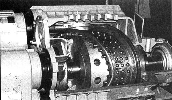
Left: The Bristol Axial Engine on a testbed.
From Some Unusual Engines by LJK Setright, pub Mechanical Engineering Publications Ltd, 1975.
Left: The Bristol Axial Engine animated
Animation by Bill Todd
![]()
Left: The Russian Sparost Cam Engine: 193?
The Soviet Air Force Museum at Monino.
Image from The Development of Aero Piston engines by Bill Gunston
Left: The Russian Sparost Cam Engine
The Soviet Air Force Museum at Monino.
Image from The Soviet Air Force Museum
Left: The Hulsebos-Hesselman axial oil engine
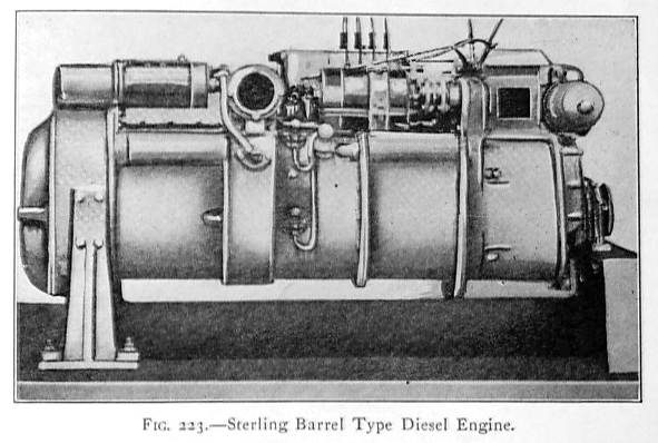
Left: The Sterling Axial Diesel Engine
Left: The Sterling Axial Diesel Engine
![]()
Left: The Alfaro swashplate engine: 1938
Image from Charles Fayette Taylor
Left: The Alfaro swashplate engine: 1938
Image kindly provided by Darren Powell.
Left: The Dyna-Cam Engine
Image from The Knife and Fork Man (Biography of Charles Redrup) by Bill Fairney
Left: The Dyna-Cam Engine internals
Image from Piston Aero Engines
Left: The Dyna-Cam Engine on test
Image from
![]()
Left: The Wooler Axial Engine: 1947.
Engine in The Science Museum, London
Left: The Wooler Axial Engine: 1947
The engine is on display in the Aeroplane Gallery of The Science Museum, London. Author's photograph.
Left: The Brandt Axial Engine: 1948
Left: The Brandt Axial Engine: 1948
Left: The Brandt Axial Engine: 1948
Echappement= exhaust
Embrayage= clutch
Left: The Brandt Axial Engine: 1948
![]()
Left: The Searle Rotocom Engine: 1981
Popular Science October 1981
Left: The Searle Rotocom Engine
Popular Science October 1981
![]()
The information on the Mk 37 here comes from the conversion manual, the full text of which can be found here. Time to update those old Mk 37s you have hanging around in the garage...
Engine start is initiated by an igniter operated by the torpedo's auxiliary power battery. As a safety measure, a water detector, located in the tailcone water inlet, prevents engine ignition prior to submerging the torpedo in water. The igniter sets off a small propellant "starting grain" which pressurizes the combustion chamber system, starts the engine, and opens the fuel interlock valve. The seawater pump supplies cooling water to the combustion chamber and the engine. The fuel pump supplies fuel to the engine from the fuel tank, a rubberized nylon fuel cell with a capacity of 26 gallons. Engine crossover time, the transition from starter grain energy to fuel burn energy, was typically 0.8 second. Fuel consumption rates were about 1.4 gallons-per-minute in tests. The Otto fuel genertates gases at up to 3600 psi. No figures for the horsepower developed have so far been found.
Left: The propulsion sytem of a converted Mark 37 torpedo
From Mark 37C Torpedo System Technical Description, NVR 73-50, 1973, a Northrop document describing updating the Mk 37 torpedo to the C version.
The engine runs on a monopropellant called Otto fuel II. (nothing to do with the Otto cycle) This fearful stuff is a mixture of three synthetic substances: propylene glycol dinitrate (the main component), 2-nitrodiphenylamine, and dibutyl sebacate. It is a red-orange oily liquid and a stable substance until vapourised and heated, when its three components react. The fuel itself is toxic and the products of combustion are also toxic, containing highly poisonous hydrogen cyanide gas. This monopropellant system is unlike earlier "heater" torpedos which carried a tank of highly compressed air for the combustion of paraffin.
Left: The back end of a Russian torpedo
Image from a special issue of "National Defense" (a Russian arms & military technologies magazine) for EURONAVAL 2008, the leading international trade fair for naval defense that took place in Paris-Le-Bourget exhibition center from 27 to 31 October 2008. This was kindly brought to my attention by Pr. Théodose Lamartre.
![]()
CURRENT AXIAL ENGINE DEVELOPMENTS: 2011-2016
Work continues on axial IC engines. Here is one company: The Axial Vector Engine Corporation (external link)
Axial Vector Engine Corp. said Thursday that is has signed a settlement agreement and mutual release with Dennis Palmer and Patricia Wilks resolving the lawsuit filed by Axial over the purchase of the Dyna-Cam assets.
The agreement was signed May 16, effective June 30. The settlement involved confirmation by Palmer and Wilks of the agreements wherein Axial acquired all rights, titles, assets and interest to Dyna-Cam Engine Corp., including related Web sites and domain names."
Gyroscope.com makes model gas engines. This video shows their 4-cylinder wobbleplate engine. Their website is not explicit but it appears that the fuel is propane. The price is Ł1,233.75.
The CoAxe Engine Company are developing a diesel cam-engine with contra-rotating output shafts.
Their website is here. There is a nice CAD animation to be seen.
Duke Engines are developing a valve-less 5 cylinder, 3 injector Axial internal combustion engine that claims to have zero first-order vibration, significantly reduced size and weight, very high power density and the ability to run on multiple fuels and bio-fuels.
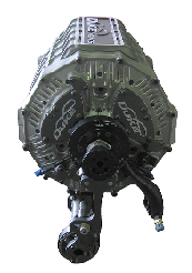
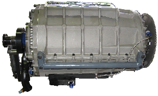
Left: Duke axial engine: 2011
![]()
![]()
