Compound Internal-Combustion Engines
|
| |
Gallery opened Mar 2007
Updated: 16 Sept 2022
More on the Work of Sperry
  
| |
The use of compounding to increase the efficiency of steam engines was common practice from many years, dating back to Hornblower in 1781. (No, not the fictional admiral, but I'll bet that's where C S Forester got the name from) But what about internal Combustion Engines? The exhaust gases are red-hot, and appear to be at considerable pressure. How about adding a low-pressure cylinder to get useful work out of these gases? That may sound like a radical notion, but it's not exactly a new one; the first attempt was made in 1879.
However, nobody managed to make the idea work. It is one of those deceptive notions that seem simple to apply, like the rotary steam engine. The reality was very different, with disabling technical difficulties.

CONTENTS OF THIS PAGE
THE DEUTZ COMPOUND ENGINE: 1879
 |
| Left: The Deutz compound engine: 1879
This water-cooled compound gas engine was built by the German Deutz company in 1879. (Deutz is a suburb of Cologne) It had two high-pressure cylinders, one on each side of the single low-pressure cylinder. The HP pistons moved in and out together; the LP crank was set at 180ş to them.
From Geschichte des Deutschen Verbrennungsmotorenbaues von 1860 bis 1918, by Friedrich Sass, pub Springer-Verlag 1962 p71
|
It is believed that the design was proposed by Gottlieb Daimler because the English patent 3245/1879 is in his name. The Germany patent number 10116 (15th August 1879) is simply in the name of the Deutz company. Gottlieb Daimler famously went on to develop early petrol engines and make early automobiles, as described in Wikipedia.
a1,a2High-pressure cylinders | d1,d2High-pressure cylinder exhaust valves
bLow-pressure cylinder | eLow-pressure cylinder exhaust valves
cValvegear cam-shaft with bevel gears for speed reduction.
| | | | | | | | | |
Gas inlet was controlled by slide valves, which can be seen at the extreme left of the engine; there was a single slide for both HP cylinders, controlled by the same camshaft c. The speed level reduction of the camshaft is achieved by the bevel gear visible near the crankshaft. The incompletely expanded gases from the two HP cylinders flow through the intermediate exhaust valves d1, d2 into the upper part of the chamber above the piston of the LP cylinder, which is supplied in turn by each of the two HP cylinders. Therefore the LP cylinder is working on a sort of two stroke cycle, in that it produces power twice as often as each HP cylinder. Through the exhaust valve e the fully expanded exhaust gases flow on each inward stroke out of the middle cylinder to the exhaust. On both sides of valve e another valve was installed. In the patent they are called "counter-valves", and they were used to block the passage to the other HP cylinder during the transfer of the hot gases. These valves were actuated by levers, presumably driven from the camshaft in some way. To ease starting the compression of all 3 cylinders could be canceled by a "Decompression" device. The means of ignition is not currently known.
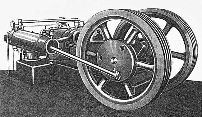 |
| Left: The Deutz compound engine: 1879
This not very satisfactory illustration appears to be a drawing traced from a photograph.
As with the Butler engine below, there are two heavy flywheels- possibly to make hit-and-miss governing practical?
From Geschichte des Deutschen Verbrennungsmotorenbaues von 1860 bis 1918, by Friedrich Sass, pub Springer-Verlag 1962 p71
|
A single engine was built, and as a precaution installed in the factory of a friendly company- the Sugar mill of Pfeifer & Langen in Elsdorf in the Rhineland, whose owners were the principal shareholders in Deutz Ltd. News of any breakdowns could therefore be kept in the family.
The engine worked there for several years; its output was about 60 HP with a gas consumption of 3/4 m3 per HP-hour. Unfortunately it appears to have given a lot of trouble. The temperature of the exhaust gases flowing from the HP to the LP cylinders was above 1000°C, and the intermediate exhaust valves had to be cooled to cope. (How is currently unknown, but probably by some sort of water-cooling) This valve cooling apparently caused most of the remaining usable energy (exergy) to be lost, and that remaining was barely able to keep the LP cylinder at idle, ie with no worthwhile power output.
The compound engine was returned from the sugar mill to Deutz Ltd in 1884, where it found a special place in the Deutz factory museum. Unfortunately it was scrapped in 1925 because of lack of space in the museum.
After all this time, The Deutz Company is still very much in existence, and still developing new IC technologies.
My heartfelt thanks to Felix Brun for translating much of the information from the German.
THE FOREST-GALLICE COMPOUND PETROL ENGINE: 1888
This remarkable compound engine has five cylinders; four HP cylinders and one central LP cylinder. It is water-cooled and uses spark ignition. It can be seen in CNAM, the Conservatoire National des Arts et Metiers, in Paris.
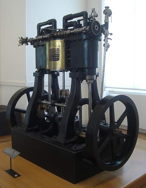 |
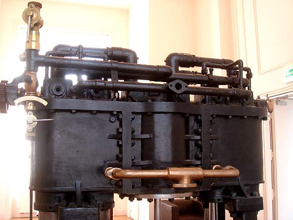
| Left: The Forest-Gallice Compound Petrol Engine: 1888
The LP cylinder is behind the brass plate in the middle of the cylinder assembly. The rather complex camshaft can be seen running horizontally just above the plate. Two connecting rods (to the right of the cylinder block) from the crankshaft drive a gear that drives the flyball governor on top, and engages with a larger gear on the end of the camshaft, giving what appears to be a 2:1 speed reduction. Note the complex pipework at the top of the cylinders. A high-tension distributor with ceramic insulators is mounted on the far end of the camshaft.
There are two HP cylinders on each side of the central LP cylinder. The museum placard states the engine was constructed for Forest on the Fernand Forest-Georges Gallice system, that the engine was reversible, and that each group of two HP cylinders could operate independently. Quite what the last statement means is currently obscure. Does it mean that you could cut out two HP cylinders when running at low power?
The engine was used on Forest's yacht the "Jolie Brise".
Engine is in CNAM, Conservatoire National des Arts et Metiers, Paris. Author's photograph.
|
 |
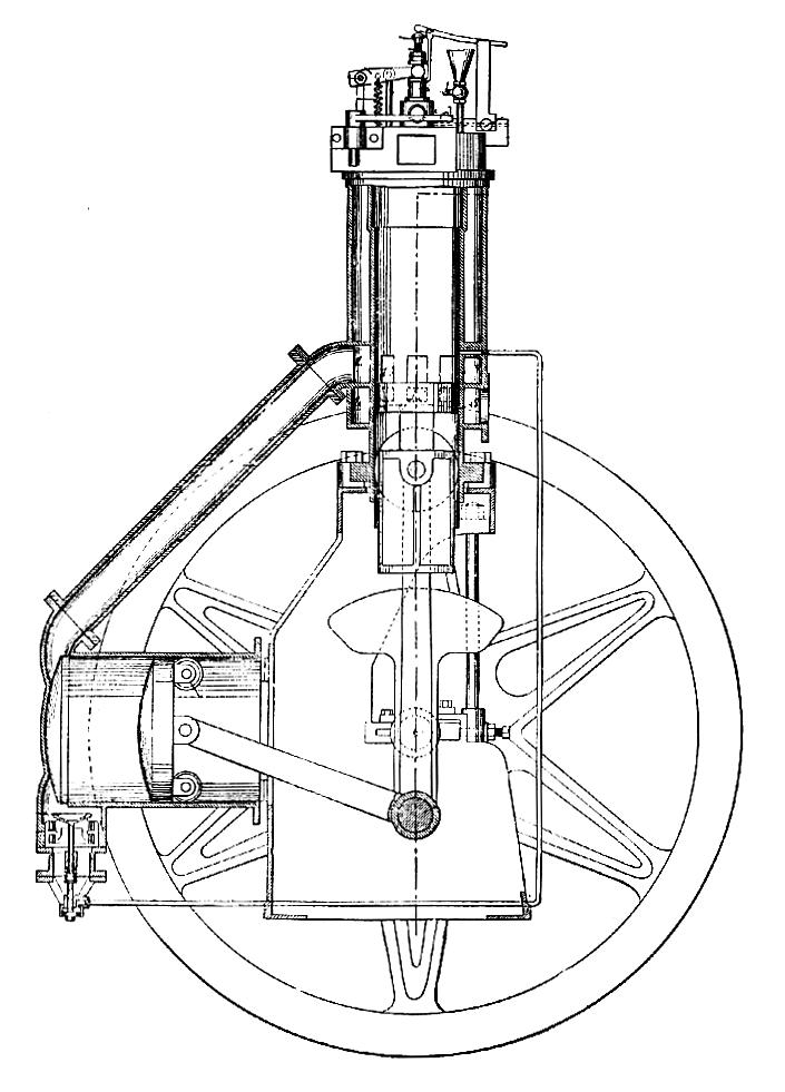
| Left: The Forest-Gallice Engine Patent, dated 1890
The drawings correspond very closely to the real engine above. Unfortunately the detail is not very clear, but it looks as though the LP cylinder is double-acting, whereas all the HP cylinders are clearly single-acting. The crank angles do not correspond with those of the Deutz engine above, where the HP pistons go in and out together. Here the two sets of HP pistons are at 180 degrees to each other.
The pipes visible above the cylinders are believed to be the HP to LP gas transfer pipes. They are somewhat indirect and completely unlagged, so they probably caused serious thermal and pressure losses, as Rudolf Diesel discovered in his compound engine.
|
 |
| Left: The Forest-Gallice Engine: 1888
The other side of the engine, the opposite side from the brass plate, showing the complicated pipework on top of the cylinders. The pipe with the two valves attached at left is probably the induction tract, but the path of the exhaust from the LP cylinder remains mysterious. There is a small flange just above the central LP cylinder but it looks too small for the exhaust pipe. The branched copper pipe below is almost certainly one the connections for water cooling.
Sorry about the contre-jour effects; flash is not allowed in CNAM.
Engine is in CNAM, Conservatoire National des Arts et Metiers, Paris. Author's photograph.
|
THE CONNELLY COMPOUND ENGINE: 1888
This compound engine, with its integral infinitely-variable-ratio drive, was invented by John S Connelly of Plainfield, New Jersey, to drive street-cars. An article describing it in the Scientific American Supplement (6 Oct 1888) devoted almost all its attention to the variable-ratio drive, and only a few words to the compound engine. While it was described as a 'gas' engine, it actually ran on naptha, an early version of petrol. The engine and drive are described in US patent 457,459. (Aug 1891)
 |
| Left: The Connelly Compound Gas Engine: 1888
A mixture of naptha vapour and air was compressed and then combusted by electric spark in the upper high-pressure (HP) cylinder. The exhaust from this cylinder did further work in the low-pressure (LP) cylinder mounted horizontally. I am still disentangling the complications of the patent text, but it appears that the LP cylinder was also used to compress the fuel-air mixture into the upper HP cylinder. If this is correct, we seem to have here a unique example of two-stage compression.
Considerable extra complication was caused by the intention to use hit-and-miss control of the engine power; in other words, on some cycles there would be no combustion and hence no gases to drive the LP piston.
An interesting feature of the patent is that it refers to compound IC engines as if they were well-known, and describes them as being noisy and prone to vibration caused by the sudden release of the exhaust from the HP to the LP cylinder.
Comment from Scientific American Supplement 6 Oct 1888
"So far as the author is aware, no compound engine has yet been made in this country, but Professor Aimé Witz, in his latest volume on the gas engine, describes one invented in America, bearing the name of Connelly, in which it is attempted to embody this principle. In this engine two cylinders of different dimensions are employed, and, whilst the explosion takes place in the smaller cylinder, the expansion of the products is completed in the larger cylinder."
From The Modern Gas Engine (1895)
|
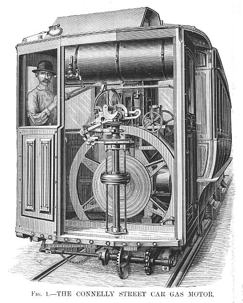 |
| Left: The Connelly Compound Gas Engine: 1888
This is the intended application of Connelly's compound engine to a street-car. The engine is partly hidden behind the large fly-wheel and the variable-ratio friction disc, but the horizontal LP cylinder can be seen to the lower right.
The variable-ratio drive was intended to give full control of speed and forward/reverse by one lever. While it was relatively sophisticated, in that the friction wheel contact pressure was varied with the amount of power transmitted, it seems highly unlikely that it could have been made to work for very long.
Scientific American Supplement: 6 Oct 1888
|
THE RUDOLF DIESEL COMPOUND ENGINE: 1897
Rudolf Diesel presented a compound engine in his 1892 patent (No. 67,207) but several years passed before he was doing practical work with his engines and could see if it actually functioned.
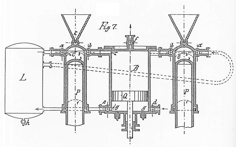 |
| Left: Diesel's proposal for a compound engine: 1892
This proposal for a compound engine fueled by coal-dust was made at a time when Diesel had only made theoretical studies of new engines. The two small cylinders on either side burn coal-dust which is injected by a blast of air from reservoir L, though how this works is obscure as no passage is shown from the conical coal hopper to the cylinder. The exhaust gases from these two cylinders operate on the top of the large central piston Q, then escape via exhaust valve f. Its underneath side compressed air to replenish reservoir L.
There is in the Museum an entire gallery devoted to solid-fuel engines. Despite immense efforts, they were not a success.
From US patent 67,207 of 1892
|
All the valves in the proposed engine shown above are of the rotary type, and would no doubt have given trouble, as rotary valves so often do. When Diesel designed an actual compound engine, he used poppet valves, as seen below.
Diesel began work on the compound engine in 1894-1895 in Berlin. Assembly of the crankshaft and main bearings began in May 1897, but the engine was not completed until June. The first indicator diagram was taken on 31st July, but serious tests did not begin until late October.
 |
| Left: Diesel's Series XIV compound engine
The Diesel compound was a three-cylinder engine that generally followed the lines of the 1892 patent. It was intended to give 120 to 150 HP. There were two 4-stroke HP cylinders of 220 mm bore and 400 mm stroke, one either side of a 2-stroke LP cylinder of 510 mm bore and the same 400 mm stroke, in the same arrangement as the Deutz engine above. The gas transfer from HP to LP cylinders was controlled by four water-cooled exhaust valves.
There were many initial problems in testing, concerned with starting and the two-plunger fuel pump, but the most unpleasant surprise was that the efficiency of the engine was not superior- it was much worse than a standard Diesel engine.
Tests revealed that the loss to the cooling water from the four intermediate exhaust valves was a shocking 11.8%, almost half of the heat that one of the cylinders could potentially convert to work. There were also unknown (but suspected to be large) heat losses from the connecting passages for gas transfer, and pumping losses in moving the hot gases from the HP to LP cylinder.
From The Diesel Engine, Cummings, p185
|
The result was that the best fuel economy achieved by the Series XIV compound engine was 499 gm/BHP-hr, more than twice the consumption of the conventional Series XV engine. It never gave more than 99 HP, well below the 150 HP aimed at.
 |
| Left: Diesel's Series XIV compound engine.
This drawing shows the large LP cylinder (left) and one of the HP combustion cylinders (right). It appears that like the Forest-Gallice engine above, the HP cylinders were single-acting but the LP cylinder was double-acting.
Note the small pipe running up the centre of the LP piston rod, to spray cooling fluid into the hollow LP piston. Whether this was water or oil is not currently known.
The arrow A shows one of the intermediate exhaust valves; this was water-cooled internally. It looks like a small valve to absorb so much heat.
From The Diesel Engine, Cummings, p185
|
The engine last ran on 31st December 1897, leaving Rudolf Diesel deeply disappointed. It was quickly dismantled and scrapped- no one wanted it hanging around as a reminder of an expensive and unsuccessful experiment.
THE BALES COMPOUND GAS ENGINE PATENT: 1897
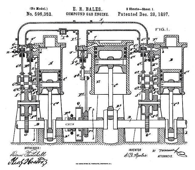 |
| Left: The Bales compound gas engine patent
This design by Edward Bales of Illinois follows the same format as the earlier engines above- two combustion cylinders with a larger LP cylinder in the middle. The former have poppet valves actuated by two gear-driven camshafts just above the crankshaft, while the valve controlling the transfer of gas from combustion to LP cylinders is driven by an eccentric on the crankshaft.
The relatively large pipe at the top of the drawing is intended to act as a receiver for the gases going to the LP cylinder, to average out the pressure changes and give a more constant impulse; the pipe seems to be fitted with a safety-valve.
All cylnders are single-acting. No cooling system is shown.
It is not so far known if this engine was ever built.
The Bales engine is unknown to Google.
From US patent 596,352 of 1897
|
If we assume that the patent drawing is to scale, then the combustion and LP cylinders have the same crank throw. Scaling from the cylinder bore, which is in the ratio 69:105, we find that the ratio between the swept volume of the combustion and LP cylinders is 1:1.52.
THE CROSSLEY-ATKINSON COMPOUND ENGINE PATENT: 1903
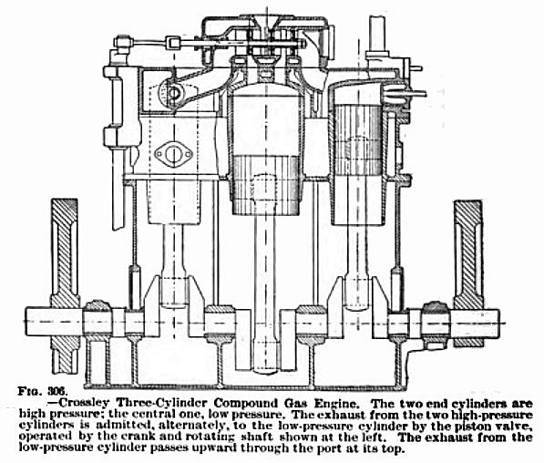 |
| Left: The Crossley Atkinson Compound Engine: 1903
This engine was constructed in England by Crossley (the well-known gas-engine company) and Atkinson. (He of the Atkinson cycle) The date of construction is unknown but was clearly some time before 1903.
From Self-Propelled Vehicles: A Practical Treatise, by James E Homans, pub Audel, New York, 1903
|
THE BABLED COMPOUND GAS ENGINE PATENT: 1903
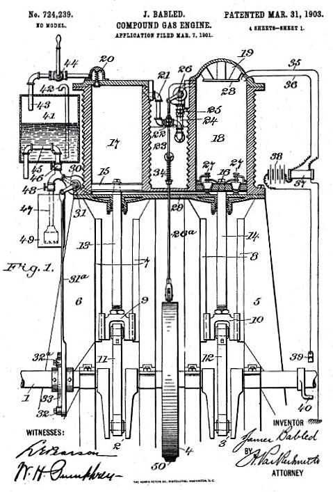 |
| Left: The Babled compound gas engine patent
This design by Jame Babled of Dallas, Texas shows little resemblance to the other compound engines on this page. Its intended mode of operation is complex, but basically cylinder 17 on the left is used to compress the inflammable mixture, but it is actually combusted in cylinder 18 on the right. After expansion here, the exhaust gases pass back to cylinder 17 via duct 29, and expand further under its piston 15.
Both cylinders are double-acting. No cooling system is shown, unless you count the suggestion of vestigial finning on the cylinders. The tank 41 at upper left is a surface carburettor.
It is not so far known if this design was ever built, but the Babled engine is certainly unknown to Google.
From US patent 724,239 of 1903
|
THE BUTLER COMPOUND ENGINES: 1904
These engines were described in an article by Edward Butler in The Electrical Magazine, 21st July 1904 issue. He was as much concerned with uniformity of torque and lack of vibrations as he was efficiency. As with the Deutz engine, there were two explosion cylinders, one on each side of a low-pressure expansion cylinder. The two explosion cylinders had their cranks at the same angle, with the expansion cylinder crank 180 degrees out of phase. The weight of the low pressure piston and rod was balanced by the sum of the two smaller pistons and rods. There were four equally-spaced explosions per cycle of two revolutions; Butler claimed that this gave smoother operation than any other arrangement.
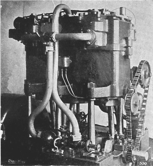 |
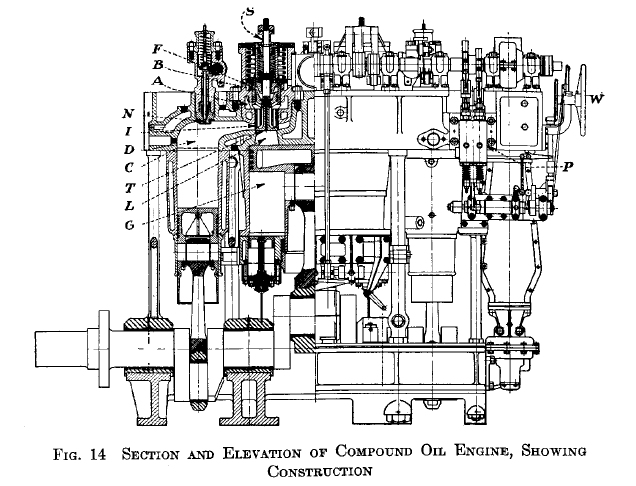
| Left: A compound high-speed oil engine.
This engine had three cylinders of 7-inch, 10-inch and 7-inch diameter, with an 8-inch stroke. This represents two high-pressure cylinders, where the combustion occurred, and one low pressure cylinder for further expansion. It had a balanced crankshaft and weighed 16 cwt. (about three-quarters of a ton)
It is not clear whether this engine was single or double-acting.
It drove a dynamo at 400 rpm.
From The Electrical Magazine, 21st July 1904, p21
|
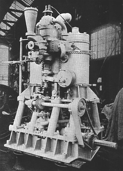 |
| Left: A 100 HP balanced compound gas engine.
This engine was built to run on either town gas or producer gas. It had variable compression and rotary valves. Unfortunately there is nothing to give much idea of the scale, but if that's a workbench visible through the flywheel on the left, the engine must have been about 10 feet high. That's a lot of engine for 100 HP.
The horizontal shaft at the front of the engine is chain-driven from the crankshaft, and drives a vertical shaft through helical gears. This presumably drove the rotary valves, though it's not clear how.
Three of this engines were built, though it is not clear by whom- probably some sort of consortium led by Butler.
From The Electrical Magazine, 21st July 1904, p23
|
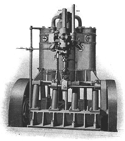 |
| Left: A 100 HP compound gas and oil engine.
This is very similar to the 100 HP engine above, though whether it was one of the three built is not clear. When running on oil a maximum of 20 HP was obtained from the low-pressure cylinder, out of the 80 HP total. This maybe points to an inherent problem in compound IC engines- an extra big cylinder and piston with associated valvegear that gave only 20% of the power.
From The Electrical Magazine, 21st July 1904, p25
|
Nothing more seems to have been heard of the idea. Why not? A likely explanation is that the amount of extra power produced from the added low-pressure cylinder was not enough to justify the cost and weight of the extra cylinder (which would of course be substantially larger than the high-pressure cylinder) and the complications of the extra valvegear. The more even torque is less of an issue with small high-speed engines such as we use now.
 |
| Left: Design for 5000 HP compound gas engine.
This was described as a "design" so it was probably never built. It was supposed to run off producer gas at what were then called "central stations" ie what we would call electric power stations. To put it into perspective, the first steam turbine power station in Britain began operation with two 75 kW turbo-alternators at Newcastle in January 1890, and the writing was already on the wall for reciprocating engines generating electricity. In 1905 Sir Charles Parsons supplied a pair of 1500 kW turbo-alternators generating at 11 kV to the Frindsbury Power Station in Kent; Butler's engines were obsolete.
Like most compound IC engines, this one had two normal cylinders in which combustion took place, flanking a central low-pressure cylinder in which the gases were further expanded.
5000 HP seems like a large power output for three cylinders, with only two of them actually combusting; from the dimensions on this drawing it appears that the engine was intended to be 31 feet high with no less than two 17 foot diameter flywheels. That is a lot of flywheel for an engine that was supposed to have a uniform torque as one of its major features.
The pistons were water-cooled internally, and were lubricated by means of oil and water dripped down the hollow tail-rods, from the pipes at the top of the drawing.
You will notice that the valves labelled C are of the rotary type. If you have visited the Museum gallery of rotary valve IC engines, you will know that despite a great deal of development, these have never proved very successful. One can only speculate how well they might have worked here.
From The Electrical Magazine, 21st July 1904, p26
|
 |
| Left: Design for 5000 HP compound gas engine.
Section of the low-pressure cylinder, showing water-cooled exhaust valves, with the water being dribbled down the tail-rod into the interior of the valves. All the other valves were of the rotary type; these were also water-cooled.
Butler says that the size of the cylinders was proportioned to give a mean pressure of 65 psi on the HP pistons and 10 psi on the LP piston. Twin sparking plugs in "firing pockets" were specified; these were to be fitted with a stop valve so that a plug could be changed while the engine was running.
From The Electrical Magazine, 21st July 1904, p26
|
 |
| Left: Design for 5000 HP compound gas engine.
Section through two of the rotary valves, at top and bottom of the cylinder. These were pressed into their seats by small pistons in cylinders that connected to the main cylinder. These can just be seen to the right of each valve. "...by this simple means any adjustment for wear or unequal expansion is automatically compensated for." asserts Mr Butler.
Note the provision of compressed-air starting.
From The Electrical Magazine, 21st July 1904, p26
|
At the end of his article, Butler notes intriguingly that the compound IC principle had also been tried out by Crossley, Livesy, Daimler, Holt, and others, though "in quite small sizes". The Museum staff are already on the trail of these engines. The Crossley engine has now been found.
EDWARD BUTLER
Edward Butler was an Englishman who built the Butler Petrol Cycle, which is accepted by many as the very first British motor car although it never went into production. Karl Benz is generally recognised as the inventor of the modern motor car, but Butler was said to have exhibited plans for a 3-wheeled vehicle some two years earlier than Benz in 1884 at the Stanley Cycle Show.
You can learn more about Mr Butler here. (Wikipedia link)
THE EISENHUTH COMPOUND ENGINE: 1900-1907
The Eisenhuth Horseless Vehicle Company, based in New York City, made an usual car called the Compound. Its engine, patented by John H Eisenhuth, had three cylinders, the outer two being high-pressure combustion cylinders, while the larger middle cylinder further expanded the exhaust gases. The three-cylinder cars were built throughout 1907, but the final Compound being a two-cylinder model. Only one of the cars survives, presrved in the USA.
 |
| Left: The Compound car: 1905
The outside of the car photographed in 1905, gives no hint of its unique engine. As far as is known the Compound make was unique; no other manufacturer used a compound IC engine. It appears to be a four-seater.
Eisenhuth met D F Graham, the maker of the Graham-Fox compound engine, and bought the Graham-Fox company. The Compound car was built in Middletown, Connecticut. Eisenhuth claimed that fuel economy was 47% better than that of an equivalant standard engine. In 1905, the Compound did rather well in the New York Motor Club's National Economy Test. To further showcase the cars technology and advantages, professors at both M.I.T. and Stevens Institute were tasked with performing independent studies of the Compound engine's fuel efficiency and horsepower. The results of their studies were published, but the Museum staff have not so far been able to track them down.
The cars were priced at $6,000, which made them one of the most expensive cars of the period, and sales were not in high volume.
In 1904, the company was sued by Colonel Frank A Fox of the Graham-Fox Motor Car Company, who claimed that he had "invented certain essential features of the motors now being made by the Eisenhuth company." which can't have been helpful.
The company went bankrupt in 1907. In 1909, the Eisenhuth factory was sold to the Noiseless Typewriter Company.
|
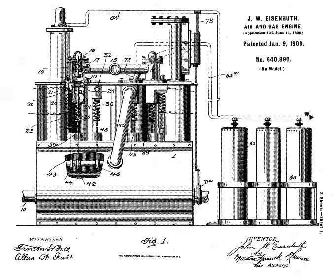 |
| Left: The Eisenhuth engine patent: 1900
The engine shown here is probably rather more complex that that fitted to the Compound cars. The two HP combustion cylinders can be seen at each end, with the large LP cylinder in the middle.
An air compressor is mounted on top of the left HP cylinder; this compressed air into the storage vessels 66 to the right. A piston air-motor, with separate eccentric-driven valve-gear, is mounted on top of the right HP cylinder. This was optionally powered by stored compressed air to give a short-term power increase. It was also intended that compressed air could be admitted directly to the LP cylinder. The exhaust from the LP cylinder exits through duct 49 and is led to a reservoir 50 mounted on the side of the crankcase, where its residual heat was to be used to increase the energy in the compressed air.
The outer cylinders had a bore of 7.5 inches, while the central low-pressure cylinder had a bore of no less than 12 inches.
It does not seem likely that all these compressed-air complications were incorporated in the car engine; if they were it would partially qualify as a compressed-air car.
From US Patent 640,890 of 1900
|
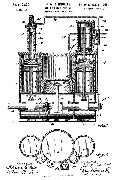 |
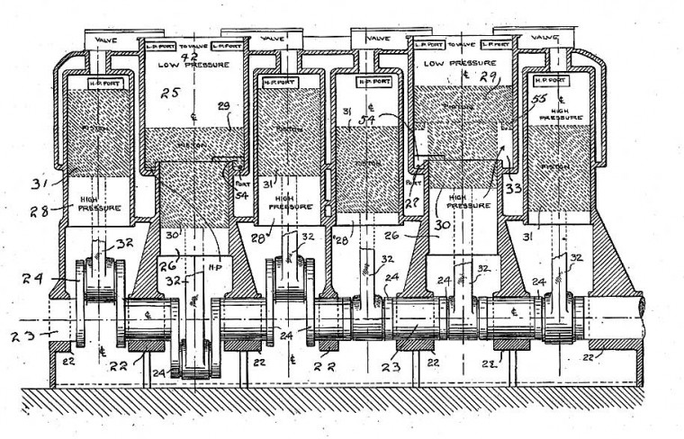
| Left: The Eisenhuth engine patent: 1900
A vertical section and plan section of the Eisenhuth engine. The air compressor 59 is mounted on top of the left HP cylinder, and the air-motor 67 on top of the right HP cylinder, with a slide valve 71 driven by the eccentric 71 on the crankshaft end. The pipes 64 and 73 carry compressed-air.
The plan in Fig 3 shows the valves 24 that transferred the exhaust gases from the HP cylinders to the LP cylinder.
From US Patent 640,460 of 1900
|
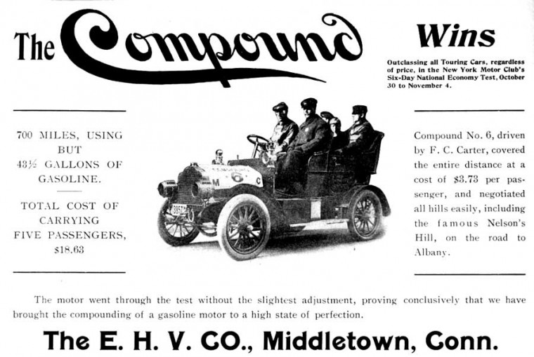 |
| Left: Compound advertisement: 1905
Not surprisingly, much was made of the good performance in the New York Motor Club's National Economy Test.
The fuel economy works out as 16.1 mpg, which would not impress anyone nowadays. Presumably many of the other competitors achieved even worse figures.
|
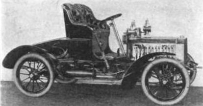 |
| Left: Two-seater Compound car: 190?
Another Compound with a three-cylinder engine; this is a two-seater.
|
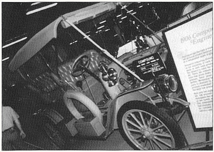 |
| Left: EHV Compound car: 1906
This vehicle used to be in the great automobile collection of William Harrah at Reno, Nevada. The collection was very expensive to maintain, and various auctions of cars were held to raise money. This vehicle apparently went to one of those auctions and its current whereabouts are unknown.
A smaller version of the Harrah collection now exists in Reno.
|
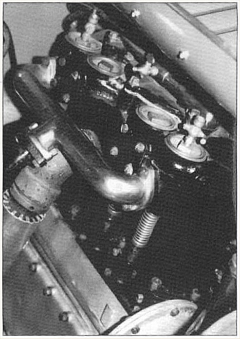 |
| Left: Engine of EHV Compound car: 1906
This is the compound engine of the EHV car shown just above. The four circular covers look as if they are at the top of the four valves for the high-pressure cylinders.
The high and low pressure cylinder heads appear to be hidden under the bonnet at top right.
The single large pipe on the left is probably the exhaust outlet from the low pressure cylinder; since there was only one no manifold was required.
|
 |
| Left: Six-cylinder compound engine: 1905
Eisenhuth clearly decided at some point that he needed a bigger engine. This is 17 years on from his US Patent 640,460 of 1900.
At first it looks as though two three-cylinder compound engines have simply been bolted together, but there is more to it. This time Eisenhuth decided to use rotary valves; see the drawing below.
Source: US patent 1,233,563 of July 1917
|
 |
| Left: Six-cylinder compound engine: 1905
For some reason Eisenhuth decided to use rotary valves in this engine. Rotary valve IC engines, like rotary steam engines, seem like an obvious improvement but for both the technical difficulties are prohibitive. This was piling doubtful complication upon doubtful complication.
The four rotary valves at left centre controlled the passage of hot gas between two HP cylinders and the LP cylinder betwen them. The two valves at right centre were the exhaust valves for the LP cylinders. The valves were rotated by bevel gears from the shaft at the right.
Source: US patent 1,233,563 of July 1917
|
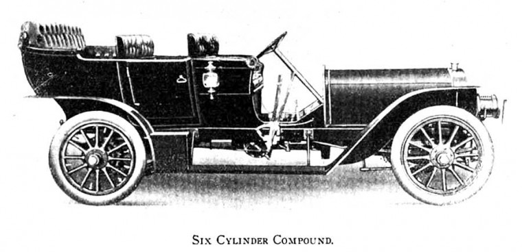 |
| Left: The six-cylinder Compound: 1905
Note the long bonnet to accommodate the six-cylinder compound engine.
|
THOUGHTS ON COMPOUNDING BY W H BOOTH: 1905
 |
| Left: Some thoughts on compounding by W H Booth
Who seems to agree that the game is not worth the candle.
Attempts to find out who Mr Booth was have so far been unsuccessful.
From an article on the Diesel engine in The Electrical Magazine, 25th April 1905 issue, p343
|
THE ABBOTT COMPOUND GAS ENGINE PATENT: 1910
 |
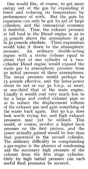
| Left: The Abbott compound engine patent: 1910
This design by William Abbott of Philadelphia, Pennsylvania, has an unusual arrangement of valves set on top of each single-acting combustion cylinder; a single poppet valve 15 opens into the top of the combustion chamber while a separately driven piston valve 13 above it routes the gases. The exhaust from the two combustion cylinders goes to the LP cylinder 17 via two pipes 34, inlet and exhaust being controlled by piston valve 25. The timing is arranged so that the two combustion cylinders exhaust alternately. The lower sides of the combustion cylinder pistons are used to compress air that is delivered to storage tank 27, which is heated by a heat exchanger through which the final exhaust from the LP cylinder passes. This compressed air is used for starting the engine, being supplied by the pipes 30.
Unlike most of the other compound engines, the LP cylinder is only single-acting. Note that water-cooling jackets are shown for both combustion and LP cylinders.
While described as a "gas-engine" it was actually supposed to run on a vapourising fuel such as paraffin, sprayed in through the cam-controlled injectors 39.
From US patent 961,059
|
THE SPERRY COMPOUND DIESEL ENGINES: 1921
Elmer Ambrose Sperry (1860-1930) is today famous for inventing gyroscopic flying instruments and the gyrocompass. Actually his work covered a wide range of subjects, including electric lighting and the design of compound diesel engines.
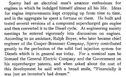
During the 1920s Elmer Sperry turned over the routine operation of the Gyroscope Company to a cadre of professional managers and turned his attention to the compound diesel engine. Correspondence with Charles Kettering of General Motors shows that by 1919 Sperry sought to develop a more efficient diesel engine. He was also convinced that flammable aviation petrol had to be replaced by a safer fuel. During the 1920s Sperry collaborated closely with H C Snow, an engineer with the Velie Motors Corporation of Moline, Illinois; a complete file of their letters shows that in spite of strenuous efforts the compound diesel project was a technological failure.
 |
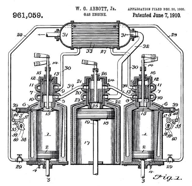
| Left: A Sperry compound diesel engine design: 1921
This diagram is from Compounding The Combustion Engine, a paper produced by Sperry. It consists of two high-pressure cylinders C with a central low-pressure cylinder G. The fuel pumps are at P and W is the "manipulating wheel" which may have controlled some sort of governor. The HP cylinder visible is at the bottom of its stroke, and the LP piston is at the top; the HP cylinders drove the LP cylinder alternately. T is the transfer valve which controlled the transfer of gases from HP to LP cylinders.
The space underneath the LP piston was used as "the first-stage annular compression pump" which exhuasted into a receiver.
There is a Wikipedia page for Elmer A Sperry, but it makes no mention of his work with IC engines.
Source: Compounding The Combustion Engine, presented to the American Society of Mechanical Engineers in December 1921. Sperry says that "...a group headed by the author has been engaged on this problem for upwards of 30 years" and claimed the work had been successful. This was not true.
|
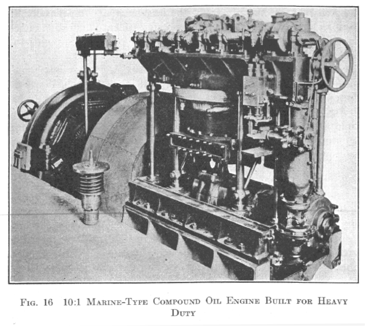 |
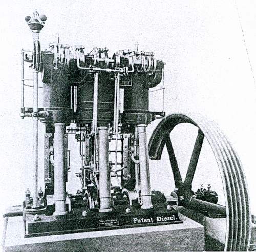
| Left: A Sperry compound diesel engine: 1921
This appears to be a photograph of the engine depicted in the diagram above, as it corresponds in every visible detail. The text says it is "the fifth compound engine of the series", and it is "a small marine type, with high-pressure cylinders 7" by 11", running at 400 rpm". 10:1 is the compression ratio.
There is a rectangular slot with bolts attached to the LP cylinder; this may have been the LP exhaust port, but is more likely to have been the air intake for "the first-stage annular compression pump" as mentioned above. In the background is the electrical generator that forms the load. Standing by the engine is one of the transfer valves. (with helical spring and bonnet)
Sperry claimed that adding the LP cylinder increased the power of the engine by a factor of seven, which seems (to put it mildly) highly unlikely.
Source: Compounding The Combustion Engine, presented to the American Society of Mechanical Engineers in December 1921.
|
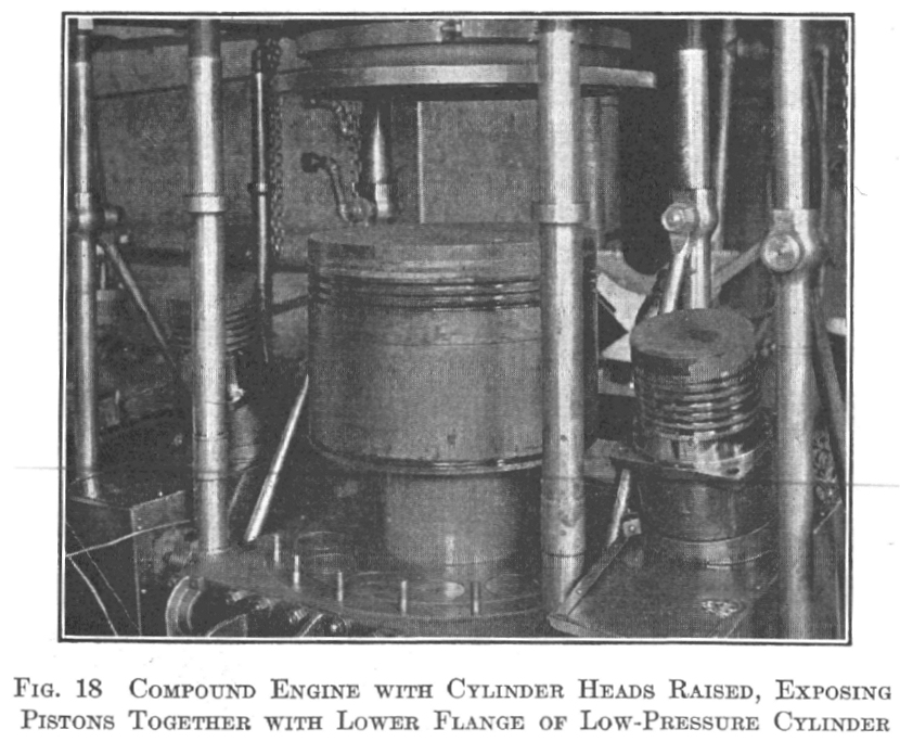 |
| Left: A Sperry compound engine: 1921
This is a different engine from that pictured just above, and the text says it is "an 8:1 compound of the same general construction" (as that above) with the cylinder head raised, showing the LP piston with the HP pistons on either side.
Beneath the step in the LP piston, the tops of the inlet valves for the "the first-stage annular compression pump" can be seen.
|
 |
| Left: Comment on Sperry compound engines: 1921
Source: taken from a biography of Sperry by J C Hunsaker, pub by National Academy Of Sciences, 1954
|
The idea of the compound IC engine seems to have disappeared for the rest of the 20th century, but, like a surprisingly large number of the concepts on display in the Museum of RetroTech, has recently resurfaced. A report from Oak Ridge Laboratory in the USA called "Advanced Combustion and Emission Control Research for High-Efficiency Engines" issued in 2004, included this rather intriguing table of IC engine power losses and possible ways of reducing them:
You will see that in the second category, that of Exhaust Losses, the "breakthrough path" includes compound compression and expansion cycles. The concept of the compound IC engine clearly lives on, a century later.
You can read the full Oak Ridge Laboratory report here. I am not quite clear whar compound compression is- possibly two stages of compression with intercooling, as used in industrial air compressors to improve the efficiency of compression.
As of 2018, interest in compound IC continues. YouTube has this video on unconventional engines. A compound engine very similiar to that Eisenhuth and his predecessors appears around the 3:20 min mark.
There are other ways of getting more power out of an engine by greater expansion of the exhaust gases, such as The Atkinson cycle. (Wikipedia link)
The original Atkinson cycle engine performed the intake, compression, power, and exhaust phases of the four-stroke cycle in a single crankshaft rotation, and was invented by James Atkinson in 1882 to bypass the contemporary patents covering Otto cycle engines. It had an unconventional connecting-rod/crankshaft linkage that allowed the exhaust stroke to be longer than the compression stroke. Modern versions, such as the engine used in the Toyota Prius hybrid petrol/electric car, do not have four cycles in one rotation; operation is conventional except that exhaust stroke is effectively longer than the compression stroke, because the inlet valve closes late.
Four-stroke engines of this type with this same type of intake valve motion but with forced induction (supercharging) are known as Miller cycle engines. Here is an article on The Miller cycle. (Wikipedia link)
