High-speed reciprocating steam engines were the last flowering of the reciprocating steam engine technology that powered the world for 150 years. In many respects they were the most advanced steam engines ever built, but they could not compete with steam turbines.
The high-speed engines were developed to generate electricity. Generators need to turn at considerable speed to work effectively. One of the first electric power stations in Britain was at Brighton, which was offering electricity to the public in 1882, and this had a Brush dynamo turning at 900 rpm to generate 8.4 kilowatts. By 1887 an American station had an alternator running at 1650 rpm. No steam engine could possibly run at such speeds, so a slow-running machine was matched to the generator by ropes and pulleys, which could absorb as much as 10% of the power produced, and took up a lot of space. As the electricity industry expanded, there was a clear need for a high-speed steam engine that could be directly coupled to a generator. Therefore there were several well-known makers of high-speed steam engines by 1912; the best-known are Willans and Belliss & Morcom, but there were many others, some of which are described below.
It is notable that the two most successful engines, the Willans, and the Belliss & Morcom, were both unconventional compared with standard steam practice; the Scott-Reavell engine was also unconventional but apparently less successful. All the other manufacturers, like Brotherhood, Scott & Mountain, Browett & Lindley, and Allen produced engines that were strikingly similiar to each other, with double-acting vertical compound cylinders, forced lubrication, and a centrifugal governor at the end of the crankshaft.

THE TECHNICAL PROBLEM
In a single acting engine, steam is applied to only one side of the piston, so the piston and connecting rod can be kept in a state of compression throughout a revolution of the crankshaft. This avoids the knocking and wear of the bearings which the push-pull operation of a double-acting engine causes, and which becomes more destructive as rotational speeds increase. Attempts to reduce the knocking by tightening the bearings increased friction and could cause destructive seizure. The history of the high-speed steam engine is to a great extent the history of how the problem of alternating forces was dealt with. Pressure lubrication of the bearings was the ultimate solution, but it took some time to appear. The work of Beauchamp Tower on hydrodynamic lubrication, which prevents the bearing metals ever touching, was a vital step forward.
THE WILLANS ENGINES: SINGLE-ACTING
P W Willans built several designs of innovative single-acting engines. However, from about the middle of the out stroke to its end, the mass of the piston is being deccelerated, and this tends to cause reversal of the piston-rod forces and cause knocking. Therefore, in a patent of 1882, Willans added air cushioning to prevent this. A supplementary piston compressed air during the upward stroke, keeping the rods in compression, and returning the stored energy in the succeeding down stroke. This process cannot have been perfect, as heat losses from the air cushion chamber would have detracted from the energy restored, but it significantly improved the smoothness of running. The big air piston also acted as a crosshead guide.
 |
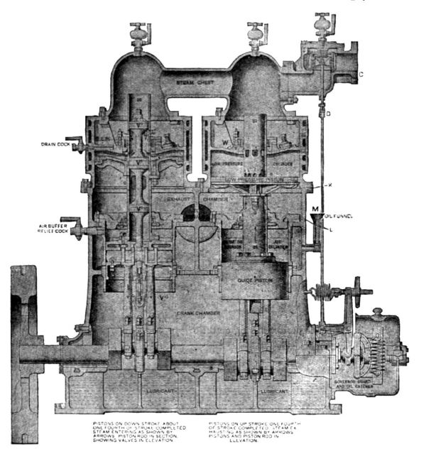
| Left: Cross-section of a double-expansion (compound) central-valve Willans engine.
The definitive high-speed Willans engine type was the "central-valve engine" as shown above. A central spindle with multiple piston valves covered and uncovered ports in the hollow piston rod; it was driven from an eccentric fixed between the two connecting rods so it moved in the correct phase. There appears to be no way to vary the cutoff; governing is here done by controlling the steam supply.
Lubrication was by the "splash" system, with the cranks dipping into the oil at the bottom the crankcase, which was therefore enclosed to prevent oil splashing everywhere. Note also the two lubricators at the top, positioned above the valve trunks.
These engines ran smoothly at 350 to 500 rpm, and were highly successful in the emerging electricity supply industry. In 1895, the installed capacity of British power stations was about 100,000 horsepower, 53,000 of which was produced by Willans engines.
|
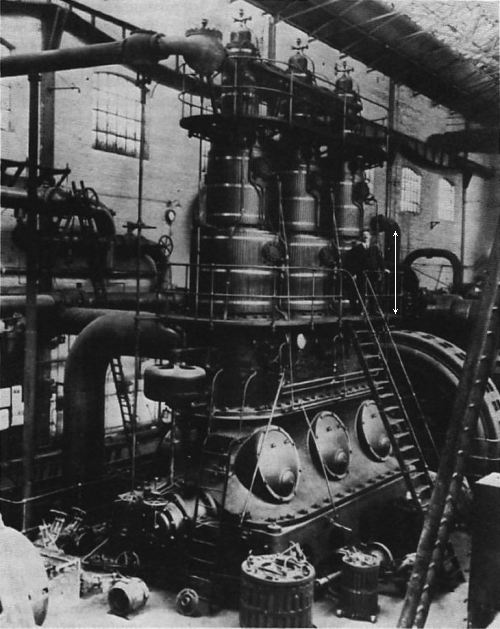 |
| Left: An impressive triple-expansion Willans engine
This machine produced 2500hp to drive the generator seen at the right. The size of the engine can be judged from the height of the man on the platform, indicated by the white arrow.
The engine is shown at Upper Boat Power Station, Treforest, Mid Glamorgan, Wales. Upper Boat Power Station was built in 1902 and demolished in 1976; the name refers to a local river ferry.
From "The Hydraulic Age" by B Pugh, 1980, who says he got it from a Mr H T Williams who worked there for 42 year
|
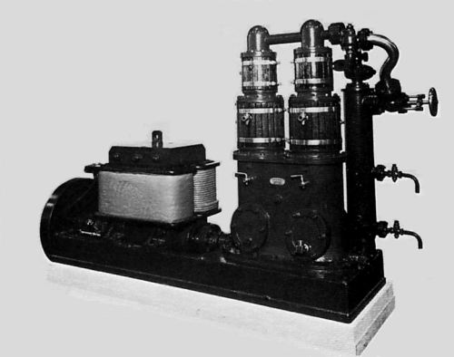 |
| Left: A small double-expansion Willans engine directly coupled to a dynamo
Unfortunately there is nothing in this picture to give the scale exactly, but judging from the size of the handwheel it is about two feet high. This engine is believed to be the specimen preserved in the Science Museum, London. If so it is rated at 10 kW at 450 rpm.
The vertical cylinder on the right is probably a steam dryer; the two cocks would indicate the level of the water acccumulating, and it would be run off through the lower cock.
|
 |
| Left: A two-cylinder single-expansion Willans engine. Note the great similarity to the compound version above
Not the most legible of diagrams but it does show details not visible on the larger drawing above.
|
Messrs. Willans & Robinson's Victoria Works opened in Rugby in 1899. For a good while they practically dominated the field. The Electrical Review in January 1892 stated that the aggregate installed power (counting units over 300HP) was 33,000HP, of which 68% was generated by direct-coupled Willans engines. At this time the Parsons turbine alternators at Newcastle only contributed 1.5% to the total. However the Belliss & Morcom engine, which had forced lubrication and so could be run double-acting, gave more power for the same space and weight, and made inroads into the market.
The development of the steam turbine eventually made reciprocating engines obsolete, and few were installed in power stations in Britain after 1914. Willans was described as making "steam turbines & oil engines" when taken over by Dick, Kerr of Kilmarnock in 1916, and they became part of the English Electric Company in 1919.
Albright & Wilson, manufacturers of phosphorus, generated their own power to run their electric furnaces. I found this aside in a history of the firm:
"The Willans steam engines, though generally speaking efficient, were subject to breakdowns, when the remains of the central valve trunks had to be carried away in buckets." And that's all he wrote. I've never seen that problem described before; I can only assume that it was due to lubrication failure, leading the central valve to seize in the valve trunking. That would probably break it. The extract comes from 100 Years of Phosphorus Making 1851 - 1951 by R E Threllfall. It does not tally with many other accounts which state that one of the main reasons for the popularity of the Willans engine for electricity generation was its reliability. Albright & Wilson have a Wikipedia page.
Reciprocating steam engines are now pretty much history, but Willans' name lives on. The "Willans Line" on a graph is still used to show steam rates at different loads on a steam turbine.
The Willans engine now has its own Wikipedia page.
Here is a typical example of the use of Willans engines at Brighton, which as we saw above started operations in 1882:
In 1891 the Brighton Corporation opened its municipal North Road Power Station on 14 September. It supplied DC at 115V, generated by four Willans-Goolden generating sets. (two at 45kW and two at 120kW) fed with steam by three Lancashire boilers. Two more Willans engines driving 240kW dynamos were added later.
By 1904 the North Road station's capacity had increased to 5,935 kW, with nineteen Willans engines coupled directly to DC generators fed by six Lancashire boilers and ten Babcock & Wilcox boilers. When a new power station was opened in 1906 the old station became less necessary, and in 1908 North Road station was closed down.
THE BELLISS & MORCOM ENGINES: DOUBLE-ACTING
 |
| Left: A Belliss & Morcom engine: circa 1900
This is a two-cylinder compound with piston valves between the cylinders. The centrifugal governor on the end of the crankshaft at the right throttles the steam supply to control engine speed.
The forced lubrication oil pump is at the bottom, in the centre of the sump. Note the dashed diagonal holes (or "oilways") shown drilled through the body of the crankshaft to distribute the oil.
|
While the single-acting engines of Willans et al ran smoothly and effectively, it was impossible to evade the fact that a double-acting engine produces more power in the same weight and volume. This was not crucial in fixed installations, but in naval use, in high-speed cruisers and torpedo-boat destroyers, it really was critical. Destroyers in particular needed to fit a lot of power into a very cramped space. These propulsion engines usually employed triple expansion with four cranks and four cylinders, the third stage of the expansion being divided between two LP cylinders.
The problem was solved by Belliss & Morcom, who built double-acting engines which used forced lubrication at the connecting rod and crankshaft bearings. In a double-acting engine the thrust acts alternately on each side of the crank-pins and cross-head pins, and without forced lubrication this produced knocking and wear unless the bearing brasses were set very tight, in which case bearing seizure was a constant possibility. Belliss & Morcom were very successful with their lightweight destroyer engines.
Belliss & Morcom also made triple-expansion engines for land use; one is preserved at the Poldark Mine. It was installed at Newton Abbot Power station in 1901 and supplied 500V DC for Torquay's Tramway; it remained in standby use until 1972.
The Belliss and Morcom engines fed their bearings with a continuous supply of oil at a pressure between 10 and 30 psi; the idea was patented in 1890 and 1892 by Mr Albert Charles Pain, a draughtsman at the Belliss works. A continuous film of oil in the bearings was therefore established, and knocking was prevented without the bearing brasses being set very close. Pain designed crankshafts and connecting-rods with holes drilled through them, so oil could be forced through these "oilways" straight into the centre of the bearings. The principle was described in a paper to the Institution of Mechanical Engineers by Alfred Morcom in 1897; it has been used in every IC engine for many years.
It seems surprising forced lubrication was not invented before this. This seems like such an obvious development that it is hard to understand how it came to be patented so late.
According to R H Parsons in The Early Days Of The Power Station Industry (1940) the Belliss engine "...was not well-suited to outputs much in excess of 1500kW" but no reason is given; perhaps alternators needed to run faster to get greater outputs economically, and any sort of reciprocating engine had limits on its rotational speed that did not exist for steam turbines.
 |
| Left: A Belliss & Morcom engine: 1927
This is a late-model two-cylinder compound running relatively fast at 525rpm. The 175HP engine gives 150kW at 2300V. As before there are piston valves between the cylinders. As in the illustration above, the HP cylinder is on the right and the LP cylinder on the left. The centrifugal governor on the end of the crankshaft throttles the steam supply to control engine speed.
The engine is driving an alternator; its DC exciter is at extreme left.
This engine is preserved at: Edmonton Power Historical Foundation in Canada
|
This website gives a lot of personal history of Belliss & Morcom but is rather light on technical detail.
It is is pleasant to record that Belliss & Morcom still exist; like Reavells they adapted by concentrating on their compressor business.
Willans, and Bellis & Morcom, are the best-known makers of high-speed steam engines of that era, but there were many others. A book published in 1912 gives details of others; see below:
SCOTT-REAVELL ENGINES: DOUBLE-ACTING ??
These were originally described here as 'Reavell engines', but further research has shown that they should more properly be called 'Scott-Reavell engines'. William Harding Scott was the brother-in-law of William Reavell, the founder of the Reavell company of Ipswich. Reavells was set up in 1898 to build both Scott's high-speed engines and William Reavell's air compressors. Scott patented his design in 1894. He had his own company, Laurence Scott & Co at Norwich, but this did not have the facilities for making his patent engine.
My father briefly worked for Reavells in the 1970's before switching to marine insurance.
Scott dealt with the force-reversal problem by cushioning the upward stroke with the compression of steam, rather than the compression of air as in the Willans engine.
Much of the information here is drawn from Fifty Years, an excellent booklet produced by Reavells which gives their history up to 1948. It is easily found as a PDF on t'net.
 |
| Left: The first Scott-Reavell engine: 1899
The first engine was a single-cylinder model giving 60 HP. It was used to provide heat and power for the newly built Reavell works at Ipswich.
The round thing to the left is a centrifugal governor, which altered the steam cutoff by rotating the vertical rod, which through cranks and levers rotated the valve sleeve inside the cylinder. See the drawings below for more details.
The engine appears to be coupled to some form of generator, though it could be a dynamometer. Between them is a massive-looking flywheel; since the engine is only single-acting more mass would have been required to smooth out speed variations over a cycle. The dial looks as if it is driven by belt from the output shaft, and it is almost certainly a rev-counter.
The lagged vertical pipe to the right is the steam supply, and the pipe to the left is the exhaust.
|
 |
| Left: Three-cylinder Scott-Reavell engine
Once again a rather hefty flywheel, depite the smoother power delivery of three rather than two cylinders. The centrifugal governor can be seen at the extreme right. Once again a rev-counter is perched above the generator, coupled to the output shaft by a belt.
|
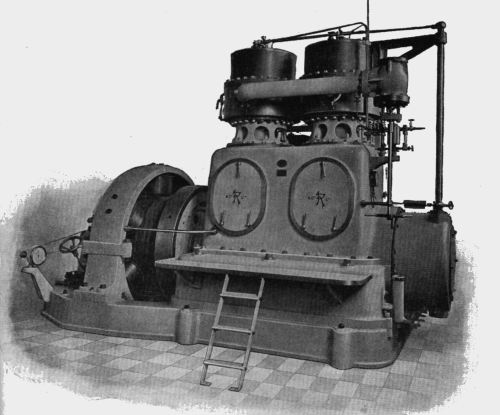 |
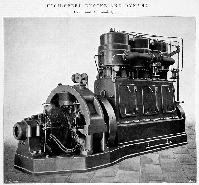
| Left: Two-cylinder Scott-Reavell engine directly coupled to a generator
The Reavell engines utilised an unusual semi-compound system, described below. The size of the engine can be judged from the stepladder in the foreground.
Note the Reavell monogram on the access doors.
|
 |
| Left: The Scott-Reavell engine in longitudinal section
The valvegear was inside a cylindrical valve sleeve, with the annular piston on the outside of this.
The Reavell engine utilised an unusual semi-compound system:
1) Piston at the top of its stroke. Steam enters inside of valve liner via ports A.
2) Steam passes through ports C into the top of the cylinder. The ports are slanted so that rotating the valve sleeve alters the steam adnission cutoff.
3) Steam is cutoff by valve D closing ports C (see lower diagram)
4) Steam expands in upper cylinder until piston finishes downstroke.
5) Ports E and G are opened by valve F and steam is transferred from top to bottom of cylinder as piston moves up. (see below)
6) After half the upstroke the transfer ports are closed. The steam in the lower part of the cylinder continues to expand. That left above the piston is compressed, cushioning the coming piston reversal and heating the cylinder ready for the next admission of steam. This is the explanation for the relatively high efficiency of these engines. At this point doubt enters as to whether the engine should be classed as single-or double-acting; it would seem to depend how much force went into compressing the steam compared with driving the crank. Fifty Years describes the operation as "... though double-acting, exerted a constant downward thrust on the crank." Splash lubrication was effective, as "the parts being in constant thrust... a large area of the bearings could be left uncovered by the retaining caps." So it seems that Scott's achievement was to get some of the advantages of compunding and a non-reversing thrust whicj allowed a very simple splash lubrication system to work.
7) At the end of the upstroke the exhaust valve opens and releases the lower steam.
|
 |
| Left: The Scott-Reavell engine in transverse section.
A form of piston valvegear was driven from a pin in the centre of the connecting-rod, via a bell-crank, visible here in the right-hand side of the crankcase. Engine speed was controlled by altering the cutoff point of valve D, rotating it via B and the governor control arm.
Lubrication was on the splash system; note crank balance weights dipping into the oil in the sump. This crude approach was no match for proper forced lubrication. Presumablt special arrngements wre made for lubricating the internal valve.
The demand for Scott-Reavell engines fell off rapidly when pressure-lubrication made possible double-acting high-speed engines without thrust reversal problems. Double-acting engines could produce twice the power from an engine of roughly the same size and weight, and Scott-Reavell engines could not compete with this. Engine production had almost totally ceased by 1908.
In 2012 Reavells was taken over by an American company and the Ipswich factory was closed.
|
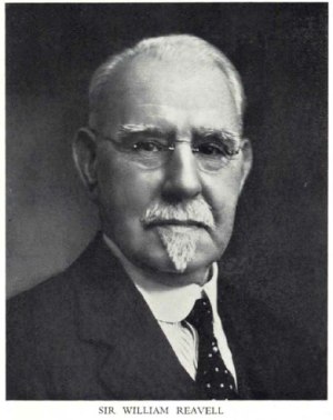 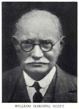 |
| Left: The founders
William Reavell was knighted in 1938. He died early in 1948.
William Harding Scott died in 1938.
|
THE BROTHERHOOD ENGINES: DOUBLE-ACTING
The firm of Brotherhood made a name for themselves with small three-cylinder radial engines, as described on the radial steam engine page. These could be used to run dynamos directly, but they also made big vertical high-speed engines to drive generators directly. The firm was founded by Peter_Brotherhood in 1907.
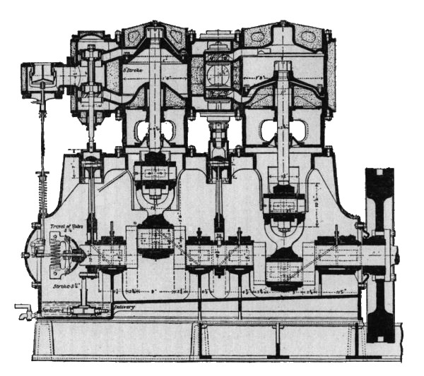 |
| Left: A Brotherhood engine: 1912
This double-acting engine used a similar form of forced lubrication to the Belliss and Morcom. Once more there are diagonal holes drilled through the crankshaft to distribute oil. The pump is a plunger type at lower left, driven from the bottom of the HP valve eccentric. There is no steam or air cushioning, so presumably the lubrication was at a high enough pressure to stop the bearings knocking on thrust reversal.
Engines of this type were supplied to the Royal Navy to drive electric generators. They ran off either 60 or 120 psi steam, and produced 150 horsepower at 450 rpm.
|
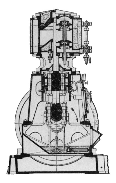 |
| Left: The Brotherhood engine in transverse section: 1912
The pistons were of forged steel, with phosphor-bronze piston rings. The piston rods and crankshaft were also of forged steel. The main bearings were of gun-metal, lined with white metal.
|
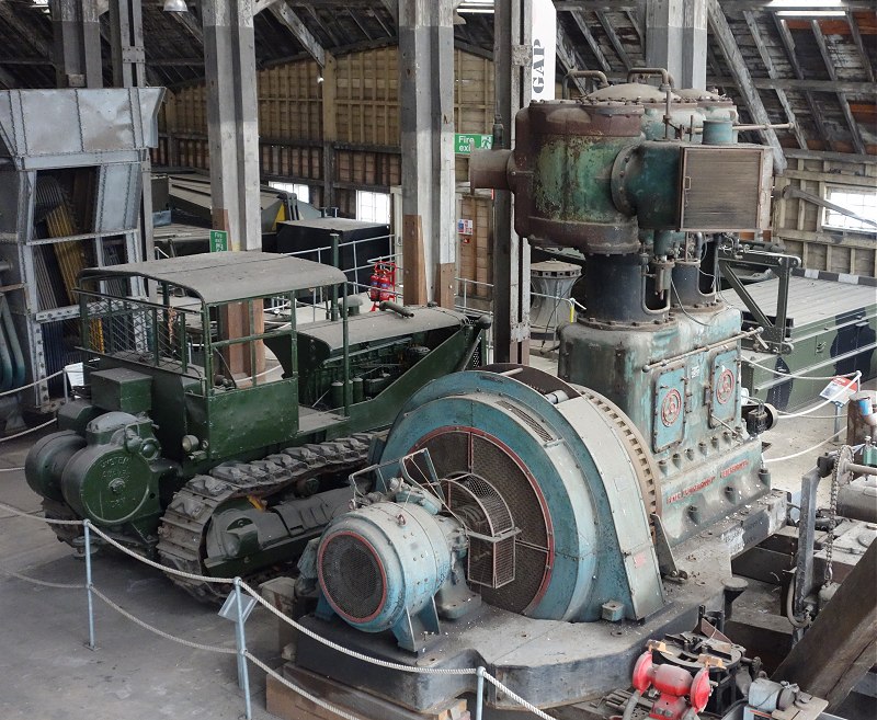 |
| Left: Brotherhood compressor at Chatham Dockyard
This machine by Brotherhood is stored in a warehouse at Chatham Dockyard. For a long time it was believed to be a compound high-speed engine coupled to an alternator, with its DC exciter to be seen at the extreme left of the engine. Scale is given by the bulldozer parked just behind it.
It is now clear that the machine is actually an air compressor, driven by a big electric motor on the left. It is unknown what the 'exciter' is.
The machine is stored rather than displayed and no information about it is given. The red lettering along the base reads 'Peter Brotherhood Ltd: Peterborough', which I think fairly positively identifies the manufacturer.
Author's photograph
|
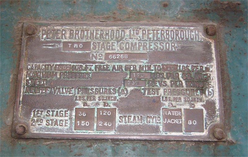 |
| Left: Nameplate on the Brotherhood compressor at Chatham Dockyard
All is revealed. It is a two-stage compressor delivering air at a maximum pressure of 120psi when turning at 250rpm. The categories a and b are obscure, but seem to indicate that the compressor could deliver air at 240psi.
There is no steam cylinder, but the plate seems to say that the cooling water jackets on the cylinders were tested to 80psi, implying the water jackets operated under pressure. This may have been to stop the cooling water from boiling. Car IC engines have pressurised cooling systems typically running at 90�C and a pressure of 3 bar. (44 psi)
|
 |
| Left: Brotherhood compressor at Chatham Dockyard
In case you are wondering about the Piranesi air of the warehouse, it s the famous No 3 slip. When it was built in 1838, it was Europe�s largest wide-span timber structure. Believe me, it's worth going there just to see this extraordinary building.
Author's photograph
|
 |
| Left: Brotherhood compressor at Chatham Dockyard
Fear me, earthling!
Another view of the cylinders. It may not be a steam engine, but it's staying here for the time being.
Author's photograph
|
Rich Colopoulos informed me some time ago that most of the questions are answered by the assumption that the machine was an engine that had been converted into an air compressor: "The item on the side of the low pressure cylinder could be an inlet flap valve assembly. That would explain the filters and there [would be] no need for a valve actuating rod."
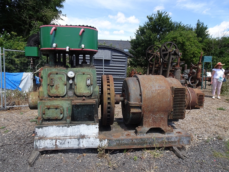 |
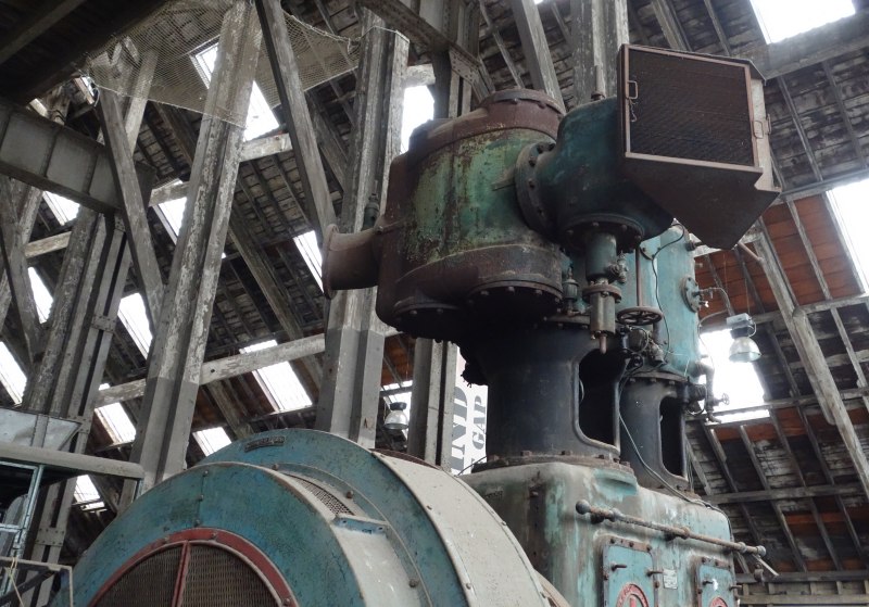
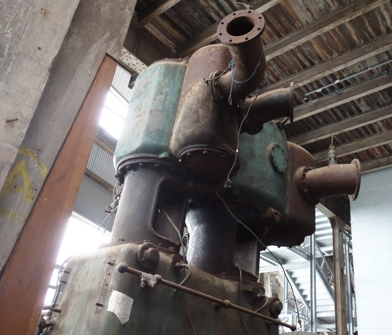
| Left: Brotherhood engine at Cambridge Museum of Technology
Two-cylinder engine coupled to a Crompton-Parkinson alternator. The exciter dynamo is at the extreme right of the machine; this generates DC to energise the field windings of the alternator.
Currently stored (outside) rather than exhibited so few details are known.
Author's photograph. July 2022
|
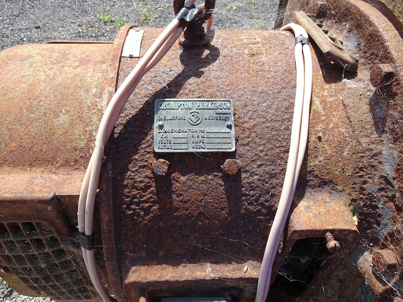 |
| Left: Exciter dynamo on Brotherhood engine at Cambridge Museum of Technology
The ratings plate on the exciter dynamo. It gives 30 Volts at 86 Amps at 500 rpm.
Author's photograph. July 2022
|
SCOTT & MOUNTAIN ENGINES
You might expect that this was the same Mr Scott as in Scott-Reavell. No. This is Ernest Scott, of Ernest Scott & Mountain of Newcastle-upon-Tyne. Mr Mountain was a person.
Messrs. Scott and Mountain Ltd, of Newcastle-on-Tyne, Britain, built a number of high-speed engines for electricity generation. Scott and Mountain also built electric motors and generators; their products were often used in the coal-mining industry for haulage.
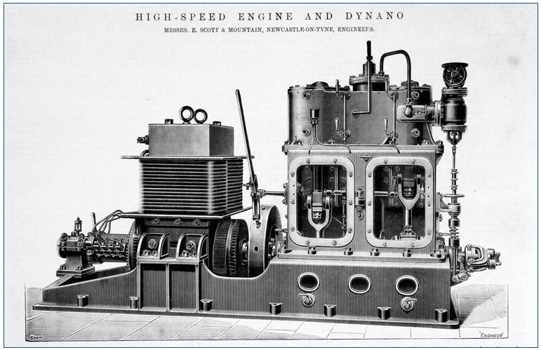 |
| Left: Early Scott and Mountain engine: 1897
This drawing of an early two-cylinder design was published in The Engineer in 1897. The crankcase access doors have been removed.
At the extreme right is a centrifugal governor, which controls the steam supply by means of the valve vertically above. The lever above the flywheel is for 'barring' the engine- ie turning it into various crank positions during maintenance. The holes in the flywheel are for insertion of the lever.
Note that something seems to have gone amiss with the spelling of 'dynamo'. Oops.
|
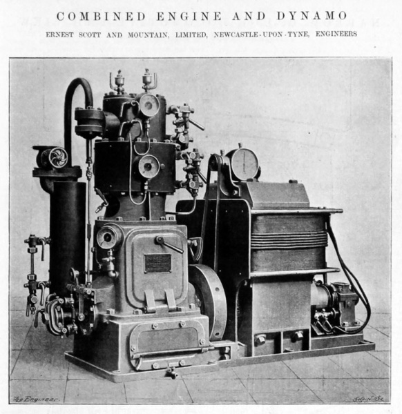 |
| Left: Scott and Mountain engine: 1900
This advert was published in February 1900. At first sight it appears to be a single-cylinder design, but the presence of two small cup lubricators on the top suggests that perhaps there are two small-diameter cylinders in the same casing.
There is a centrifugal governor mounted on the end of the crankshaft. The vertical cylinder to the left is a steam dryer that removed liquid water from the incoming steam. Build-up of water in the casing would be indicated by the tube gauge and water drained via the cock just below it.
Note the belt-driven rev-counter mounted above the dynamo.
|
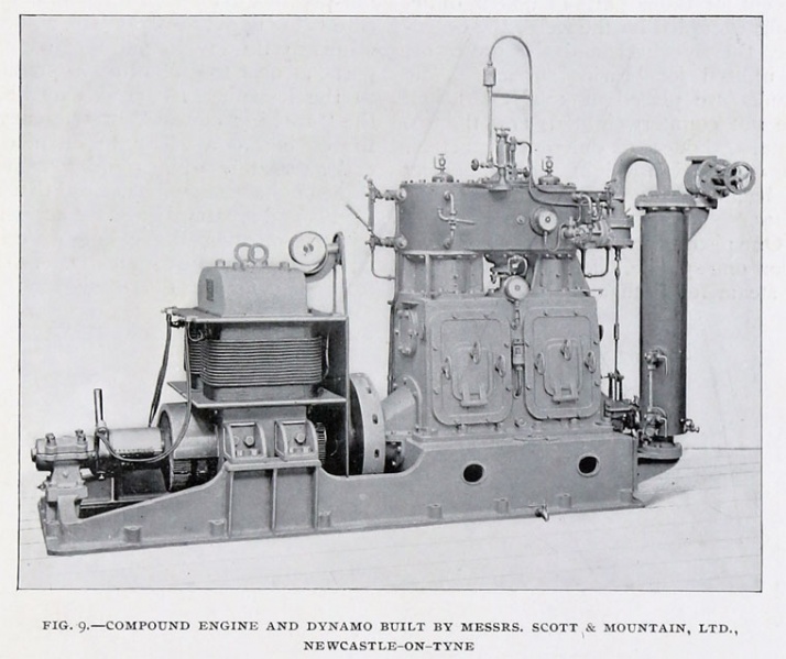 |
| Left: Scott and Mountain engine: 1901
This is a compound engine, with the HP cylinder to the right and the LP to the left, judging by the size of the casings. This advert was published in February 1901.
Once again there is a centrifugal governor mounted on the end of the crankshaft, and a cylindrical steam dryer. with level gauge and drain cock.
|
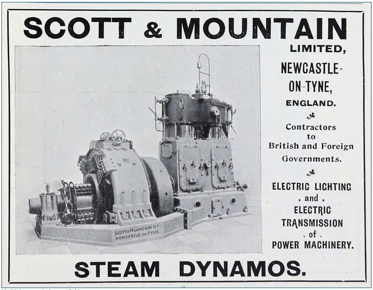 |
| Left: Scott and Mountain engine: 1901
It is not clear if this is a simple or compound engine, but it certainly has a more modern-looking dynamo. The advert was published in February 1901.
|
 |
| Left: Three-cylinder compound engine by Scott and Mountain
Here there was one high-pressure and two low-pressure cylinders, driving cranks set at 120 degrees, for good balance. The date of this design is not currently known.
These engines were mostly used to drive electric generators. Forced lubrication was provided by a valveless oil pump.
|
In 1901 Scott and Mountain supplied high-speed steam dynamos for the Birkenhead Tramway.
In 1913 the company was acquired by C A Parsons and Co.
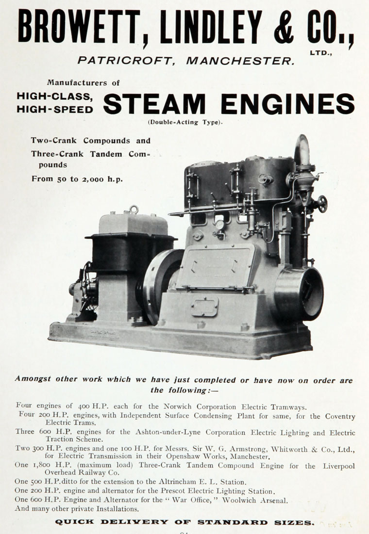
BROWETT, LINDLEY ENGINES: DOUBLE-ACTING
Browett, Lindley were a Manchester firm originally founded in 1880. They were predominantly makers of high speed engines, but they did make three large cotton mill engines.
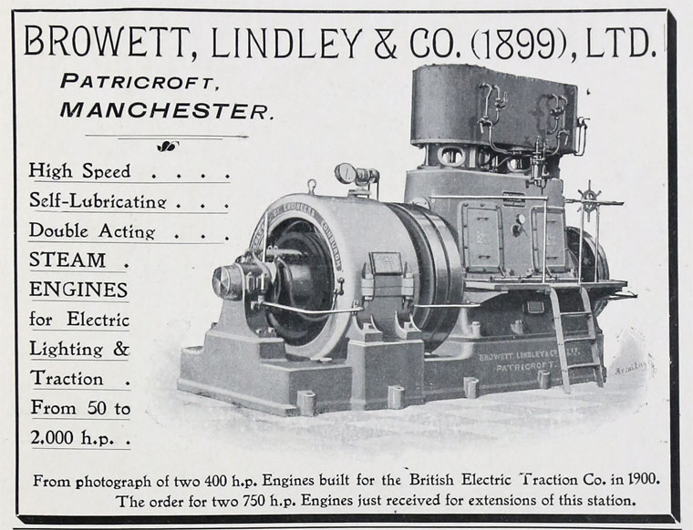 |
| Left: Browett, Lindley engine: 1902
This advert was published in 1902. The 1899 date refers to the year B & L was registered as a limited company; before that it was run as a private company.
|
 |
| Left: Browett, Lindley engine: 1900
These drawings appear to be of an engine very much like the one in the photograph just above.
All pretty standard high-speed engine stuff; double acting compound engine with piston-valves driven by eccentrics on the crankshaft. There is the usual centrifugal governor mounted on the end of the crankshaft, and controlling a steam inlet valve.
There is a cylinder in the bottom of the sump that appears to be a reciprocating oil pump driven by a bell-crank from the LP valve eccentric.
|
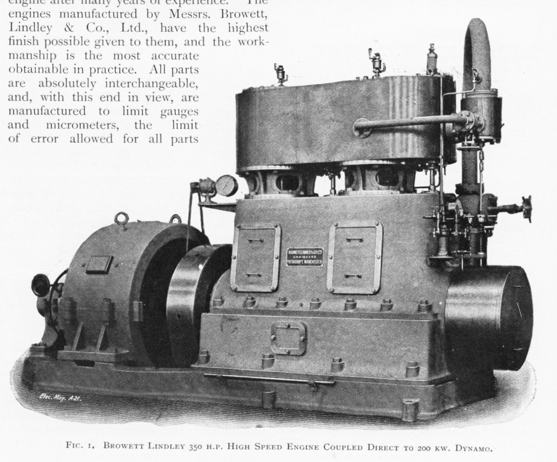 |
| Left: Browett, Lindley engine: 1902
A 350 horsepower engine is equivalent to 261kW, compared with the 200kW rating of the dynamo.
Note the holes in the flywheel for barring (turning it by hand) with a lever.
Published in The Electrical Magazine in June 1905.
|
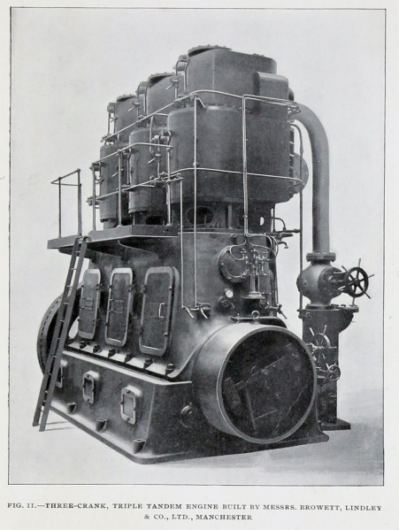 |
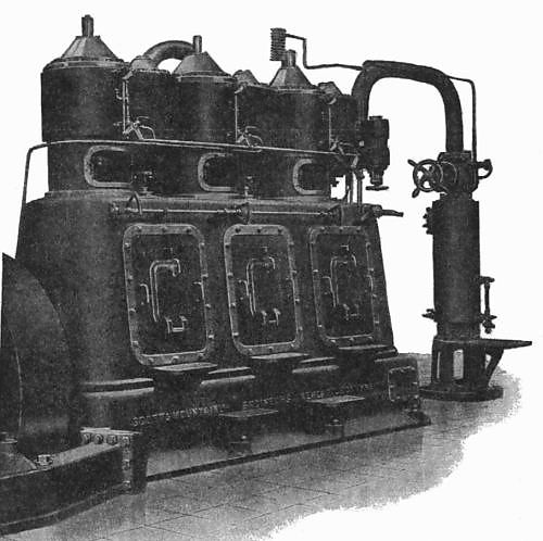
| Left: Browett, Lindley engine: 1901
This is a triple tandem engine; it has HP and LP cylinders on the same piston rod, with the smaller HP cylinders at the top. This gave a very compact assembly of 6 cylinders. The power output is not definitely known, but it seems likely this engine is the 1800 HP example referred to in the advertisment just below.
This picture was published in 1901.
|
 |
| Left: Browett, Lindley advertisment
Note the reference to a three-crank tandem compound engine for the Liverpool Overhead Railway Company; I suspect this refers to the engine pictured just above.
This engine looks very similiar to the engine below in the Bolton Steam Museum, but there are minor differences.
|
In 1929, Receivers were appointed for the company; as a result it was found that the Company Secretary had been taking money from the company for 20 years. (See The Times, Jul 31, 1929)
In 1952 the company was sold to Alley and MacLellan, and in 1954 it closed.
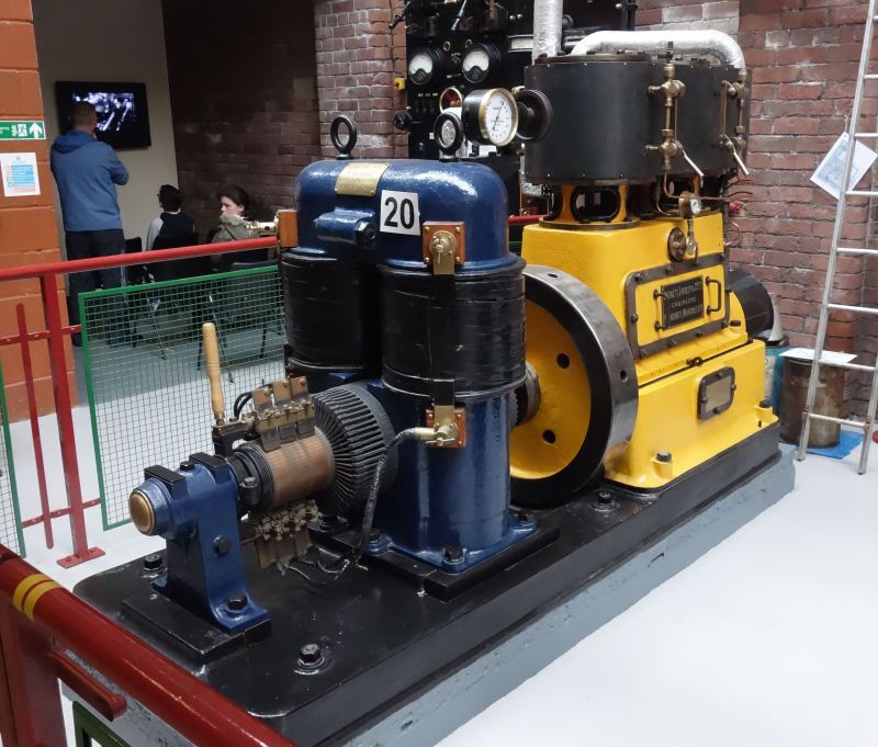 |
| Left: A Browett, Lindley engine today, in the Bolton Steam Museum
This engine was built in 1900 for Thomas Nuttall & Sons, to provide electric lighting for one of their mills. It has a 7-inch diameter HP cylinder and an 11-inch LP cylinder, with a 6-inch stroke. It produced about 45 horsepower at 560 rpm.
It was later used at Bolton Technical College as a laboratory engine.
Author's photograph.
|
The engine above is coupled to the original 110V 240Amp DC dynamo with open commutator and copper-gauze brushes, built by J H Holmes of Newcastle-upon-Tyne. J H Holmes supplied the original equipment to make Lord Armstrong's home the first house in the world to be lit by electricity.
As for several other engines at the Bolton Steam Museum, this engine is regularly run on steam at 80 psi; note the silver lagged pipes above the cylinders. It is a very fine museum with many working engines.
Browett & Lindley has a Wikipedia page.
SENTINEL HIGH-SPEED ENGINES: DOUBLE-ACTING
The Sentinel company is best-known for its steam wagons and steam locomotives, but it also made high-speed steam engines.
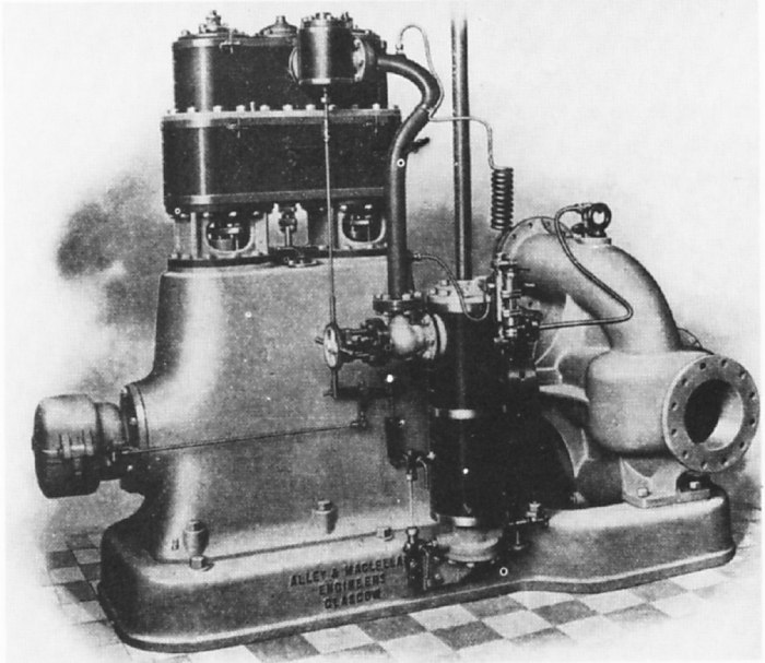 |
| Left: Sentinel engine: circa 1904
This is a twin-tandem compound engine connected to the firm's own 'Sentinel' centrifugal pump. At extreme left a centrifugal givernor is mounted on the crankshaft.
You can see 'Alley & MacLellan' on the baseplate. These were the two men who founded what became the Sentinel Company.
|
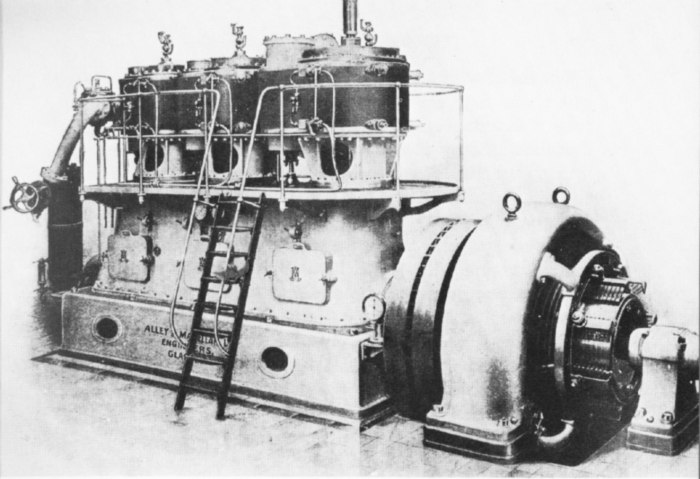 |
| Left: Sentinel engine: 1902
This is a double-acting triple-expansion engine with piston valves, driving a 500kW DC generator. The HP cylinder is at the far end, with the LP cylinder at the generator end.
'Alley & MacLellan' is on the baseplate again.
|
CAREL ENGINES: SINGLE-ACTING
Unlike the other engines here, which were all British, the Carel engine hailed from Belgium. The nameplate on the side read: "Soci�t� Anonyme des Moteurs � Grand Vitesse. Brevet Carels. Sclessin-Li�ge". It was another single-acting design, similar to the much better-known Willans engine, and with the same limitations in output for a given weight and volume. It had the same air-cushion system.
Carels Fr�res have their own (rather brief) Wikipedia page.
The main difference was the use of a rotary valve between the cylinders to control steam admission, transfer, and exhaust, driven from the crankshaft by bevel gears. Doubts were expressed by contemporary commentators about the steam-tightness of rotary valves in general, and bearing in mind what happened to The Paget Locomotive, they were probably right. In the field of engines, the very word "rotary" seems to guarantee intractable problems. In my discussion of Rotary Steam Engines, I give my theory as to why this should be so.
 |
| Left: A Carel four-cylinder compound engine.
This design relied on the less satisfactory splash system for lubrication. The rotary valves were cast-iron, rotating in phosphor-bronze sleeves and with the driving fitted with ball-bearings.
Rotary valves have given trouble in other applications. One wonders how well they worked here.
|
THE ALLEN ENGINES
W H Allen were established in 1880 at Lambeth but moved to Bedford in 1894. In 1968 they merged with Belliss and Morcom, to form the Amalgamated Power Engineering company; in 1992 this became part of Rolls-Royce. They were building high-speed steam engines up to 1914 at least, but after 1920 they seen to have focused more on oil-engines.
 |
| Left: Allen engine: 1904
This compound engine was described in Engineering for 6 May, 1904. It was built for the Bedford Corporation electric generating station, where it was coupled to a 500 kW single-phase alternator. The engine was designed for 735 BHP at 300 rpm, when fed with steam at 120 psi and exhausting into a condenser vacuum of 5in of mercury.
|
The engine had an HP cylinder of 18in diameter and two LP cylinders of 24in diameter; all had a 15in stroke. The three pistons were arrange to be of equal weight and the cranks set at 120 degrees. At the right in the sump can be seen the oil pump which provided forced lubrication at 15psi; it was driven from the HP valve eccentric. The centrifugal governor is at the extreme right end of the crankshaft.
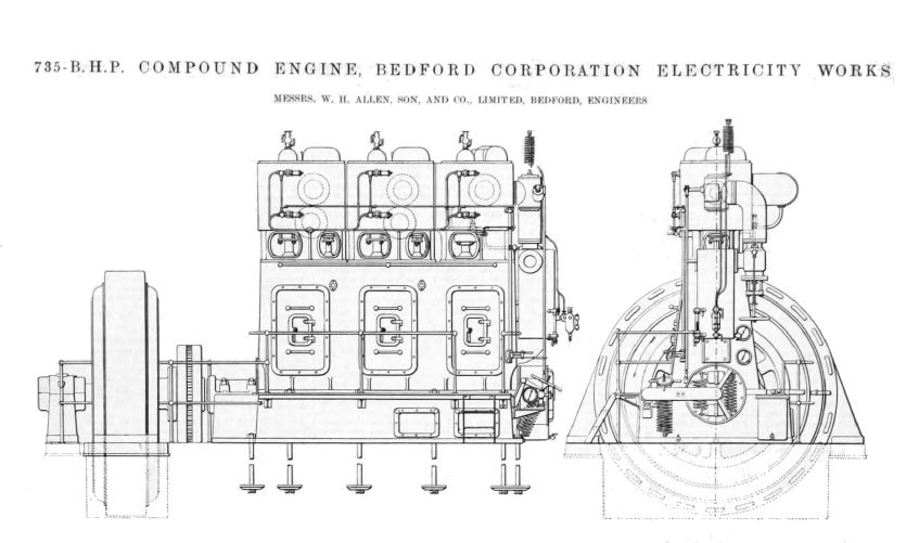 |
| Left: Allen engine and alternator: 1904
From Engineering for 6 May 1904
|
THE BUMSTED-CHANDLER ENGINES
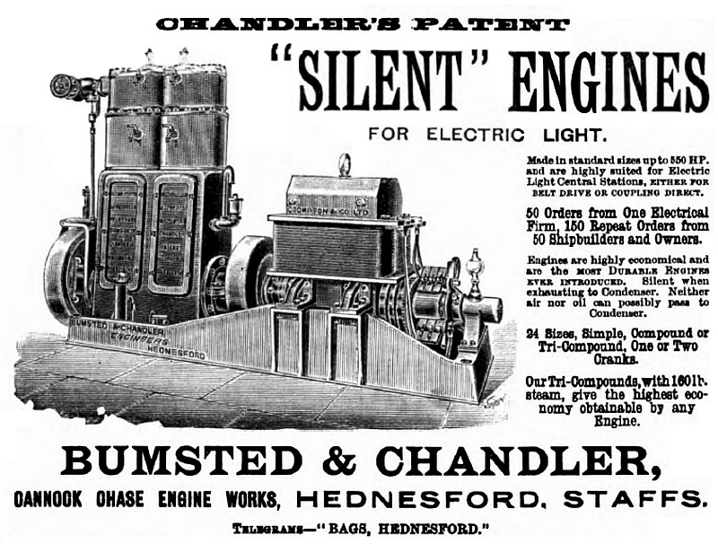 |
| Left: Bumsted-Chandler engine: 1895
An advertisement for Chandler engines that makes some ambitious claims. Note dynamo made by Crompton. That looks like a commutator at the right, so presumably it was a dynamo generating DC. Chandler "Silent" engines were also used to drive forced-draught fans for ship boiler-rooms. There is more info on Bumsted & Chandler in Graces Guide.
"Silent when exhausting to condenser." Hard to see how this could be the case if there was any pressure at all left when the exhaust valves opened.
"Neither air nor oil can reach the condenser." Why not?
" Our tri-compound engines, with 160 lb steam, give the highest economy obtainable by any engine." This seems a very large claim. Presumably tri-compound means triple expansion.
Nothing has so far been found to explain what made these engine 'Silent'.
Source: Engineering Vol 59, 04 Jan 1895, p66
|
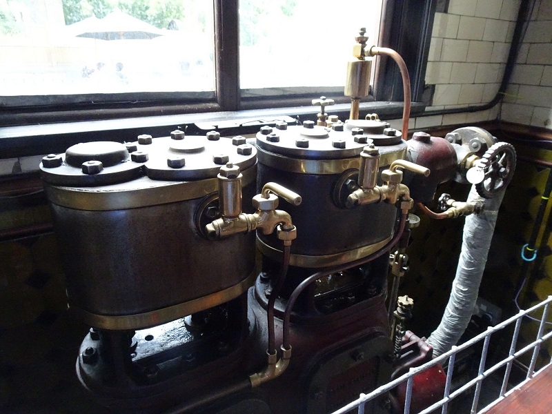 |
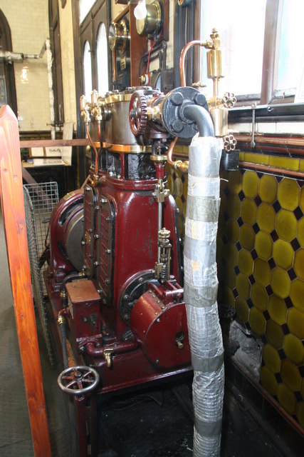
| Left: Chandler engine at Cambridge Museum of Technology
This engine is in the Cambridge Museum of Technology. It originally generated electricity for lighting at the Cambridge Sewage pumping station. The building no longer pumps sewage but houses the museum. A visit is highly recommended.
The engine is a simple (non-compound) two-cylinder single-acting design rated at 4 HP at 700 rpm. (quite fast for a steam engine) According to this site the engine consumes a lot of steam at 700 rpm.
The insulated pipe on the right brings in steam to the stop valve. (with numbered tag) Just to the left is the red housing of the governor valve.
The two brass cocks are the cylinder drains (for the removal of condensed water) which would have been opened when starting from cold. The adjacent brass cylinders are spring loaded relief valves that release the water if the cocks are closed, to avoid the cylinder head being knocked off. The drains join together and run downwards to the left.
Author's photograph July 2022
|
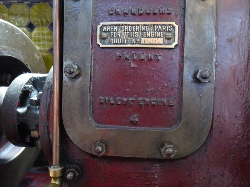 |
| Left: Inspection plate on Chandler engine at Cambridge Museum of Technology
It cannot be assumed from the brass plate that at least 1992 of these engines were made. Manufacturers often have a sneaky habit of starting serial numbers at say No 100, to disguise the fact that No 1 is a new design and maybe not fully proven. I have done it myself.
The engine simply carries the name Chandler rather than Bumsted-Chandler. Being called Bumsted may not have been much help in the business world.
The copper cylinder drain pipe is on the left.
Author's photograph July 2022
|
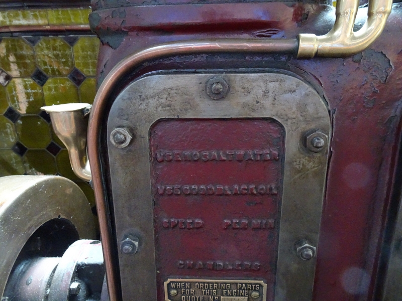 |
| Left: Inspection plate on Chandler engine at Cambridge Museum of Technology: pic 2022
The text is blurred by many coats of paint, but the top line reads "USE NO SALT WATER"; it is not clear what this means as water goes into the boiler, not the engine. The second line says "USE GOOD BLACK OIL" which is not much of a specification for a lubricant.
The speed does not seem to be specified.
Author's photograph July 2022
|
 |
| Left: Chandler engine at Cambridge Museum of Technology: pic 2022
At bottom centre is the round housing of the centrifugal governor, with a control rod going up to the governor valve. Many high speed steam engines used the same arrangement.
|
Not a lot of progress has been made in finding out why Chandler called their engines 'Silent'. The text below is supposedly from Scientific American Supplement #4, but it has not so far been located in that journal. Nor has
"IMPROVED HIGH SPEED STEAM ENGINE.
The use of rapidly rotating machinery in electric lighting has created a demand for engines running from 400 to 1,200 revolutions per minute, and capable of being coupled directly to a dynamo machine. We have already illustrated several forms of these engines, and now publish engravings of another in which the most noticeable feature is the employment of separate expansion valves and very short steam passages. Many high-speed engines labor under the well-grounded suspicion of being heavy steam users, and their want of economy often precludes their employment. Mr. Chandler, the inventor of the engine illustrated above, has therefore adopted a more elaborate arrangement of valves than ordinarily obtains in engines of this class, and claims that he gains thereby an additional economy of 33 per cent. in steam. The valves are cylindrical, and are driven by independent eccentrics, the spindle of the cut-off valve passing through the center of the main valve. The upper valve is exposed to the steam on its top face, and works in a cylinder with a groove cut around its inner surface."
"As soon as the lower edge of the valve passes below the bottom lip of the groove, the steam is cut off from the space between it and the main valve, which is fitted with packing rings and works over a latticed port. This port opens directly into the cylinder. The exhaust takes place chiefly through a port uncovered when the piston is approaching the end of its stroke. The remaining vapor left in the cylinder is exhausted under the lower edge of the main valve, until cushioning commences, and the steam from both upper and lower ports is discharged into the exhaust box shown in Fig. 2. The speed of the engine is controlled by a centrifugal governor and an equilibrium valve. This is a "dead face" valve, and when the engine is running empty it opens and closes many times per minute. The spindle on which the valve is mounted revolves with the governor pulley, and consequently never sticks. To prevent the small gland being jammed by unequal screwing up, the pressure is applied by a loose flange which is rounded at the part which presses against the gland."
"Another economy claimed for this engine is in the use of oil. The cranks and connecting rods work in a closed chamber, the lower part of which is filled with oil and water. The oil floats in a layer on the surface of the water, and at every revolution is splashed all over the working parts, including the interior of the cylinder, which it reaches through holes in the piston. The oil is maintained exactly at one level by a very ingenious arrangement. The bottom of the crank chamber communicates through a hole, C, with an outer box, which receives the water deposited by the exhaust steam. The level of this water is exactly determined by an overflow hole, B, which allows all excess above that level to pass into an elbow of the exhaust pipe, out of which it is licked by the passing steam and carried away. Thus, as the oil is gradually used the pressure of the water in the other leg of the hydrostatic balance raises the level of the remaining portion. When a fresh supply of oil is poured into the box, it forces out some of the water and descends very nearly to the level of the hole, B."
"The engine is made with either one or two cylinders, and is, of course, single-acting. The pistons and connecting rods are of forged steel and phosphor-bronze. The following is a list of their sizes:"
|
Unfortunately the accompanying diagrams have not so far been found, and it doesn't make things much clearer, but sounds as if the secret is in the exhaust valve arrangements. If we assume that the loudest event in the steam cycle is the opening of the exhaust valve when there is a significant steam pressure in the cylinder, (I have no idea if this is true) then some sort of gradual opening of this valve may well be quieter.
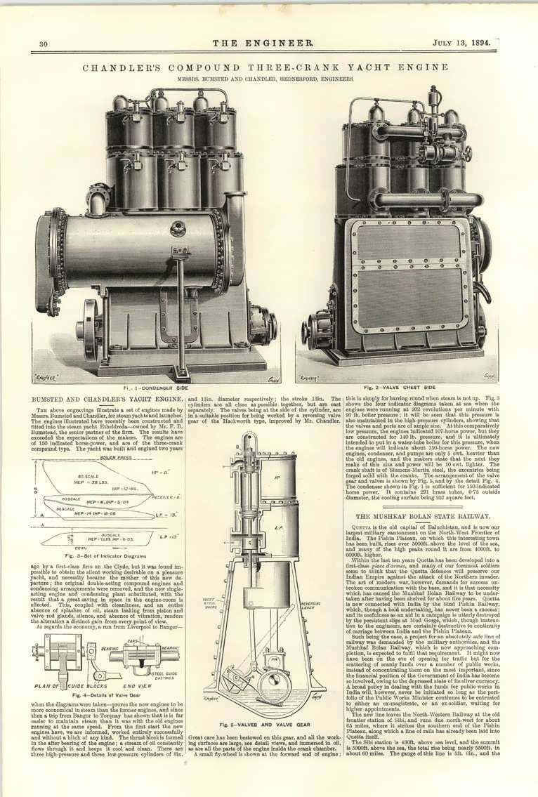 |
| Left: Chandler engine to power a yacht: 1894
The text claims that the Chandler engine was silent compared with the one it replaced, but gives no reason why. This was not intended to be a high-speed engine.
Source The Engineer 13 July 1894
|
THE ASHWORTH & PARKER ENGINES
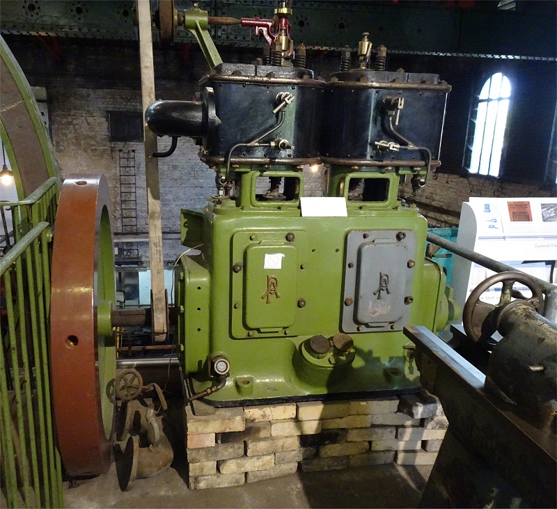 |
| Left: Ashworth & Parker engine at Cambridge Museum of Technology: pic 2022
This engine was identified by the linked A and P on the access covers. Ashworth & Parker's factory was Riverside Works, Bury, Lancashire. They have a page in Graces Guide.
Not much info is available on this engine. It is stored, rather than displayed, at the Cambridge Museum of Technology. It is a two-cylinder engine; it is not currently known if it was single or double-acting. It is simple rather than compound.
Unusually , there is a belt-driven fly-ball governor on top of the engine; regrettably the top of it is missing from my photograph. This always seems to me a risky business as if the belt snapped the throttle would open wide, possibly causing the engine to race to destruction.
The engine is not coupled to anything.
Author's photograph July 2022
|
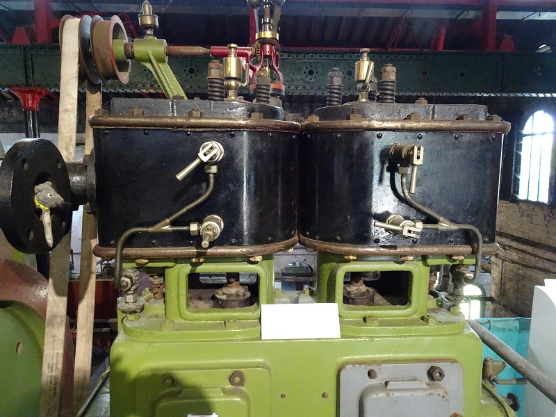 |
| Left: Ashworth & Parker engine at Cambridge Museum of Technology: pic 2022
Close-up of the cylinders, showing the cylinder drain cocks and the spring relief valves. Note stuffed rat emerging from what is presumably the exhaust pipe on the left.
Author's photograph July 2022
|
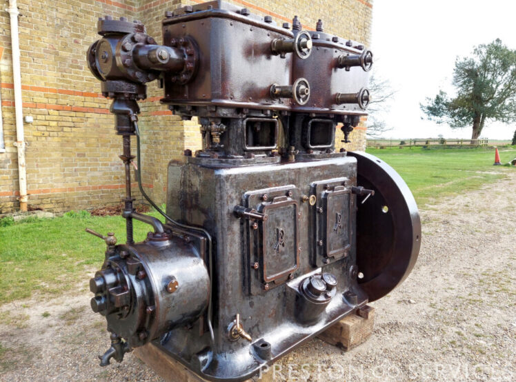 |
| Left: Ashworth & Parker engine offered for sale
This Ashworth & Parker engine was offered for sale at Preston Services. It was sold for an unknown sum.
Note that this engine has the governor on the end of the crankshaft at the left (as for nearly all high-speed engines) rather than on top as on the Cambridge Museum of Technology engine above. Crankshaft mounting eliminates the potential problems of an unreliable belt driving the governor, and I suspect that is why it was almost universal. A high-speed engine would have a relatively small amount of inertia and might accelerate to dangerous speeds much faster than a big slow mill-engine.
|
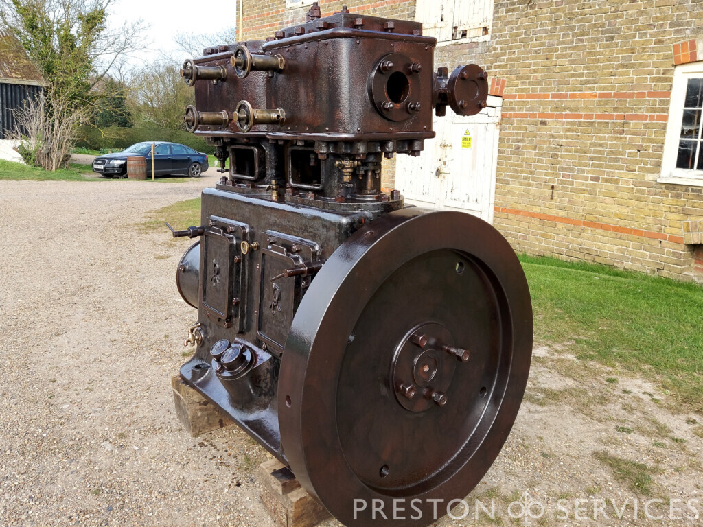 |
| Left: Ashworth & Parker engine offered for sale
Note handwheels for the cylinder drain-cocks.
|
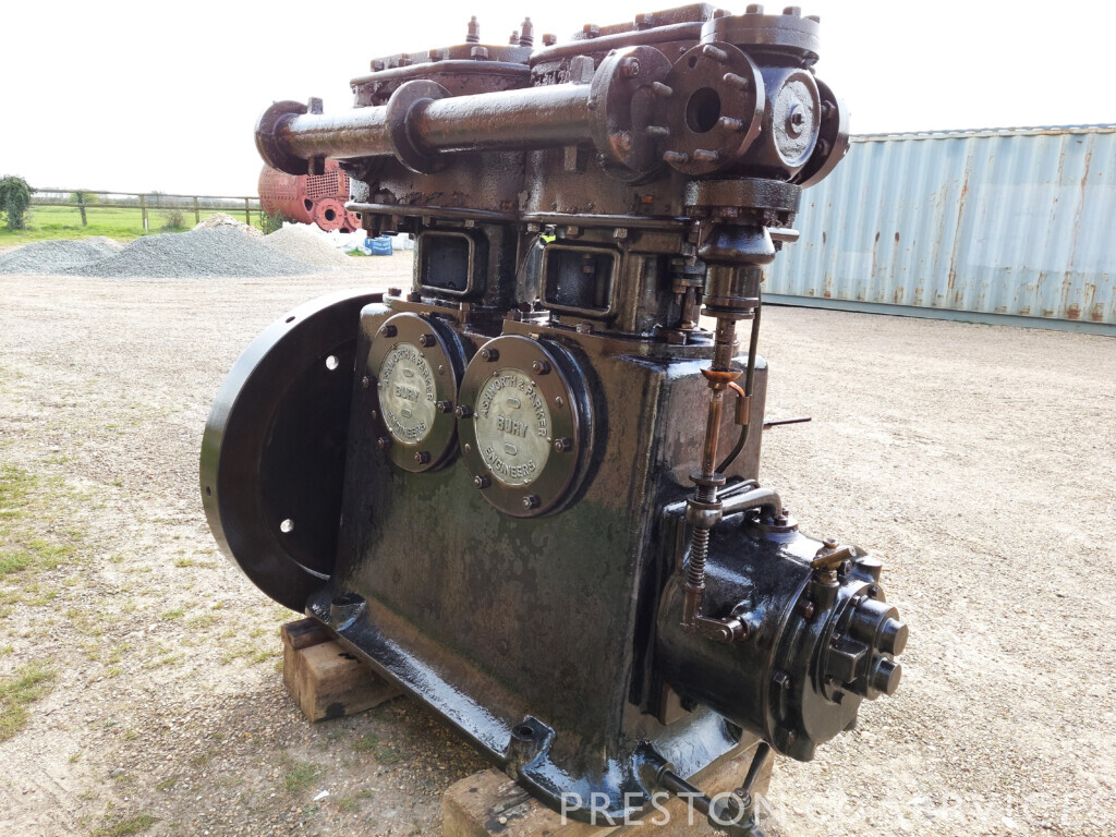 |
| Left: Ashworth & Parker engine offered for sale
|
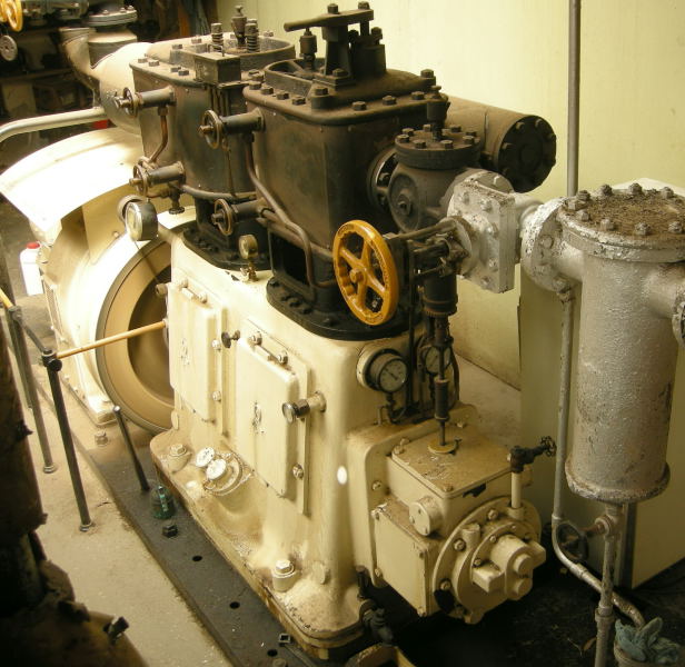 |
| Left: Ashworth & Parker engine: 1956
Ashworth and Parker steam engine driving electrical generator at Collins Bros sawmill in New Zealand.
Note governor on the end of the crankshaft, with vertical rod to the black governor valve. As with most of these engines, the governor valve is as close to the cylinder as possible, to minimise the amount of steam that will expand if the load is suddenly removed, and so minimise the transient rise in engine speed. An improvement on this was the 'automatic' steam engine in which the governor controlled the timing or 'cut-off' of the cylinder inlet valves to get a faster response. See Wikipedia.
The manual shutoff valve has a yellow handwheel. The silver cylinder at extreme right appears to be a steam dryer. Note handwheels for the cylinder drain-cocks.
|
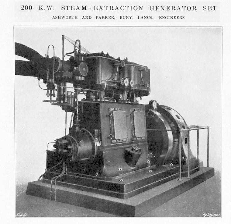 |
| Left: Ashworth & Parker engine at Cambridge Museum of Technology: pic 2022
Steam Extraction usually refers to taking steam from the main flow before it has passed through the final turbine stage. Since high-speed steam engines run from a relatively high pressure it is not currently clear what is meant here.
The governor is at the left.
|
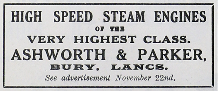 |
| Left: Ashworth & Parker engine advert: date unknown
|


