Rotating-block engines have a cylinder assembly that rotates, the rotation being brought about in an unconventional way. The category does not include relatively conventional rotary aircraft engines like the Gnome, where the radial cylinders rotate around a fixed crankshaft.
Related designs, such as toroidal engines, have now been moved to their own pages in the interest of faster downloads. See the Unusual IC Engines page for a full list.
This web page currently provides only a small selection of the many moving-cylinder-block engines that have been brought forward. The dates given here are not necessarily the date on which the proposal was made public, the patent was filed, or anything else precise. It simply means that the project was being actively developed and promoted at that time.
If you know of any good rotary IC engines that should be here, please let me know...
The list below links you to details of the engine, where such details exist on the page. Please ignore the #-numbers, this is just a filing system that attempts to keep all this organised.

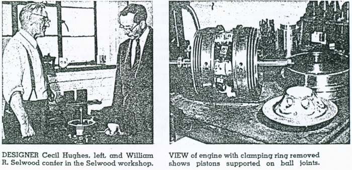
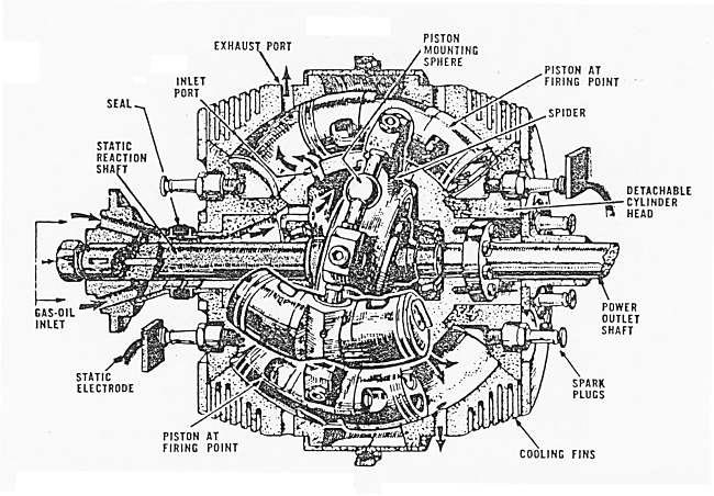
THE SELWOOD-HUGHES ORBITAL ENGINE: 1961
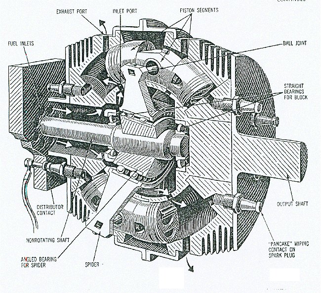 |
| Left: The Selwood-Hughes Orbital engine: 1961.
Inventor: Cecil Hughes, UK
In this design, 6 curved double-ended pistons moved in cylinders in a block that rotated around a stationary shaft. An angled spider in the centre of the engine converted piston thrust to rotation of the engine block, in a similar manner to a swashplate engine. The output shaft was connected to the engine block.
The engine is a piston-ported two-stroke; (thanks, Bill) gas deflectors can be seen on top of the pistons. There were 12 power impulses per revolution. The spider was set at an angle of 15 degrees.
From Popular Science Aug 1961
|
 |
| Left: The Selwood-Hughes Orbital engine animated.
Note that the frame of reference has been changed in this animation so that the cylinder block is stationary, and the normally stationary shaft revolves, in order to make the operation clearer.
Animation by Bill Todd, The World's Leading Animator of Perverse Internal Combustion Engines.
|
The "Selwood" part of the name comes from William R Selwood, who appears to have been the financial backer for the prototype. Selwood was a Welshman from Neath whose major interest was construction machinery. The Selwood organisation still exists; see here.
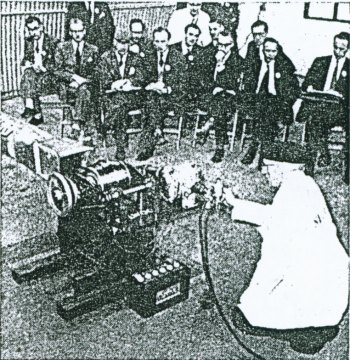 |
| Left: The Selwood-Hughes Orbital engine demo.
The engine was demonstrated near Southampton to an audience from Ford, Rolls-Royce and Bristol-Siddeley in early 1961, but nothing seems to have come of this. The duct at left leads away the exhaust fumes.
By the time of this demo Hughes said that the engine had run for 300 hours over the last year, at speeds of up to 4000 rpm.
From Popular Science Aug 1961
|
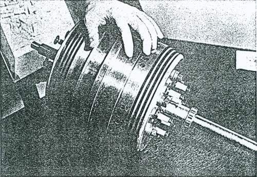 |
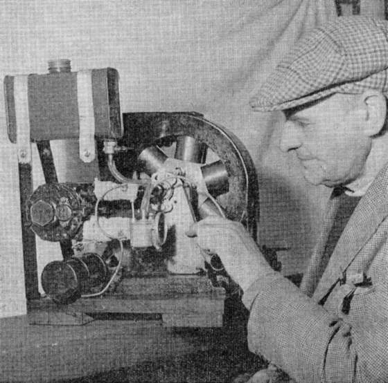
| Left: The Selwood-Hughes Orbital engine prototype.
This shows the vestigial cooling fins of the real prototype, as opposed to the more extensive finning in the drawing above. It is difficult to see how this could have given adequate cooling, even it was spinning. The sparkplugs can be seen sticking out of the right end of the engine.
The prototype weighed 100 pounds and had a displacement of 42 cubic inches. (704 cc) Hughes (who was an experienced builder of motor racing engines, claimed it was capable of 12,000 rpm.
From Mechanix Illustrated Jan 1962
|
 |
|
Above: Self-explanatory pictures of the Selwood-Hughes Orbital engine. From Mechanix Illustrated Jan 1962
Mr Selwood wonders if he should not have stuck to the construction business.
|
 |
| Left: The Selwood-Hughes Orbital engine: 1961.
Another diagram of the engine.
From Mechanix Illustrated Jan 1962
|
The engine was described in Engineering in the issues for 5 May 1961, p637, and 19 May 1961, p682.
THE MERCER CAM ENGINE.
 |
| Left: The Mercer Cam engine: 1964.
Originator: Austin Mercer of Bradford, Yorkshire, UK
In this design, pistons with rollers press against the inside of a cam section, causing the cylinder assembly to rotate by a sort of wedging action.
This is essentially a two-stroke cycle with each cylinder giving two power strokes per revolutiont; a six-cylinder Mercer engine has an impulse frequency equivalent to that of ordinary two-strokes with 12 cylinders, or a four-stroke with 24 cylinders. The petrol/air is supplied via the hollow shaft and the central rotary valve (a blower is necessary between carburettor and engine, as there is no possibility of crancase compression) The exhaust exits through ports in the side of the cylinder when these are uncovered by the piston.
This is the exact IC equivalent of
The Ljungström "Crankless" Steam Engine of 1900.
|
 |
| Left: Artist's Impression of the Mercer engine: 1964.
The rollers here are working at a massive mechanical disadvantage, trying to squeeze their way round the cam, and I need convincing that this can be done without serious frictional losses. Another point is that the surrounding cam structure needs to be mechanically strong and so will be heavy.
In 1962 it was said that plans were in hand for a further experimental version of the Mercer engine, a four-cylinder type for installation in a motorcycle. It is so far not known if this (presumably larger) engine was ever built.
From an article by Edgar T Westbury, April 1962; It is not clear in which journal this appeared.
|
 |
| Left: The prototype, presumably with Mr Mercer
The prototype had six cylinders of 1.125 inch bore and stroke. (111 cc total displacement) It was run at up to 1500 rpm.
The carburettor can be seen to the left of Mr Mercer's hand. The black cylinder mounted on the wooden base appears to be the ignition coil, while the larger cylinder to the side of the engine is presumably the blower. It is not clear how this was driven; probably by a belt on the other side of the engine.
From an article by Edgar T Westbury, April 1962; It is not clear in which journal this appeared.
|
THE MURRAY ROTORCAM.
 |
| Left: The Murray Rotorcam: 1991.
Originator: Jerome Murray, USA
In this design, four cylinders rotate due to the thrust of the roller pressing against the inside of a large elliptical cam track. The variable compression facility offered from 7:1 to 17:1, giving a multi-fuel capability. A 1.3 litre prototype was running on a dynamometer in 1991.
The beak-shaped items may be counterweights to balance the piston forces.
This is another IC equivalent of
The Ljungström "Crankless" Steam Engine of 1900.
|


