Gallery opened: June 2008
Updated: 7 July 2020
Working model Churchward & Messenger engine added


Axial Steam Engines |
Gallery opened: June 2008 |
CONTENTS OF THIS PAGE |
![]()
THE PROPOSED SCHOTT ENGINE: 1870
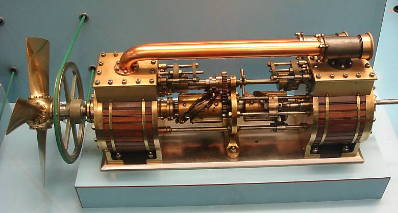 | Left: The Shott Axial Engine: 1870
|
This is a demonstration model of a proposed marine steam engine built by George Shott (of Messrs. John Penn and Sons) with the assistance of his two sons George and William Nesbitt Shott. The full-size version was to have two cylinders of 36 in diameter by 18 in stroke, fitted with piston rods and rollers to engage with grooves in two cylindrical cams mounted on the propellor shaft. Two similar but smaller cams on a separate shaft, driven by gears from the main shaft, operated the steam admission and exhaust valves. The propellor shaft passes through the centre of the aft cylinder and piston, and was to be fitted with a four-blade bronze propellor of 7.5 ft diameter. There is no provision for a thrust bearing on the model.
The engine was expected to develop about 520 indicated HP at 120 rpm, with steam at 25 psi. Its claimed advantage was presumably that the fore-and-aft engine format would fit better into a ship hull. No record of full-scale construction has been found.
There is a YouTube video of the model in operation.
THE CHURCHWARD & MESSENGER ENGINE: 1877
![]()
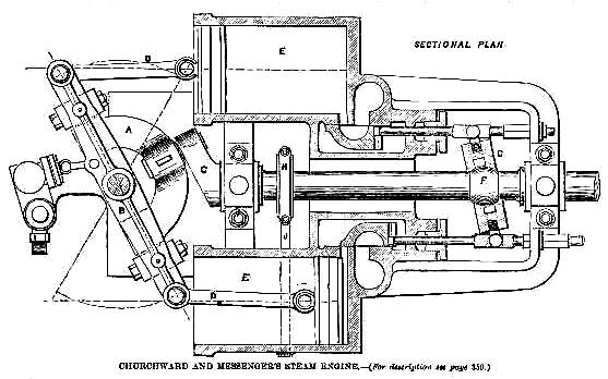 | Left: The Churchward & Messenger Engine: 1877.
|
Here is the original text from The Engineer, 16 November 1877, p359.
"Considering the necessity for reducing the space occupied by marine engines to a minimum, it is perhaps somewhat surprising that the possible advantages attending the application for this purpose of the principle of the Z crank have not been made available, at least for launch or small steamboat propulsion. Except, however, with single-acting engines this has not been done with practical success. We illustrate at page 345 a small launch engine, by Mr.J.Churchward, Dover, in which the principle is applied to single-acting cylinders, but which by the employment of trunk pistons may be made double-acting. The result is a very compact engine of long stroke, the height of the engines being little more than the diameter of the cylinders. In small launches the engine is placed under the smoke-box end of the boiler-locomotive-so that only the space necessary for the latter is required, the engine being in otherwise unused space, and its weight brought to the lowest position possible."As will be seen, the two cylinders E are placed horizontally with their axes parallel to the crank shaft, on either side of which they are fixed, the three axes being in the same horizontal plane. The crankshaft runs in bearings, one between the forward end of the cylinders and the other at the stern end of the frame. At the forward end of the cylinders is attached a bracket carrying a vertical pin upon which a horizontally vibrating arm B is pivoted, the ends of the arm being connected to the piston rods O, also by vertical pins. Upon horizontal pins or bearings a short distance from the end joints of the vibrating arm is pivoted a semicircular arm A capable of vertical vibration , the central portion of this arm being provided with a journal into which the crank pin fits. These two vibrating arms thus form bell-crank levers for each cylinder, the motion of the pistons in the direction of the length of the boat being attended by the thrust of the crank pin in a direction at a right angle thereto, the crank pin journal in the semicircular arm being permitted to follow the circular path of the crank pin by the vertical angular play of the arm A on the bearings at its two ends - the two rocking arms, in fact, forming a Hook�s joint, by which the reciprocation of the pistons produces rotation of the crankshaft. "The slide valves are worked by means of a sheave G mounted upon a pin through the crank shaft, and capable of rocking thereon through an angle sufficient to cause the pins on the sheave strap to travel the distance of the full stroke of the valves. A long feather sliding in a key bed in the crankshaft is connected with this sheave and with the sheave H worked by the reversing lever indicated at J by dotted lines, and by it the sheave G may be placed at any angle necessary for altering the cut-off, and may be placed on either side of an angle of 90 deg. For reversing the engine. By means of this concentric cam and strap for moving the slide valves, any range of expansion may be used, and the lead remains constant, whatever the range, both backward and forward running. When the engine is used for stationary purposes, a governor is attached to the fly-wheel, consisting merely of two weighted levers, the inner ends of which are jointed to a cam on the crank shaft, to which the outer end of the feather above mentioned is attached. An arrangement of automatic expansion gear is thus obtained. Our illustration only shows the design for small single-acting engines, several details of which would necessarily require modification for engines of larger power. One of the 2-horse size has now been at work about eighteen months, and has for a small engine proved very economical in fuel, and shows no particular wear in any of its parts. One new bronze piston ring has been renewed during the time mentioned, but the other ring, being of phosphor bronze, has remained good yet. The engines may be made with any number of cylinders, and the principle of the design has been applied by the inventors to other purposes, as for pumps and water meters." |
 | Left: The Churchward & Messenger Engine animated.
|
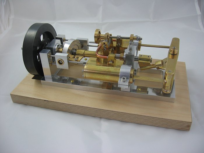 | Left: The Churchward & Messenger Engine modelled by Gerd Niephaus
|
![]()
THE WEST ENGINE: 1878
 | Left: The West Axial Engine patent: 1875
|
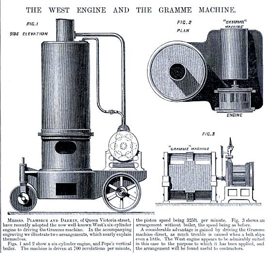 | Left: The West Axial Engine: 1878
|
  | Left: The West Axial Engine: 1878
|
A SIX CYLINDER AXIAL STEAM ENGINE: 1884
![]()
 | Left: Six-Piston Axial Engine: 1884.
|
 | Left: Six-Piston Axial Engine: 1884.
|
THE KNICKERBOCKER AXIAL ENGINE: 1899
![]()
 | Left: Knickerbocker Four-Piston Axial Engine: 1899
|
Extensive searching has so far failed to unearth any US patent covering this engine.
THE BEADLE AXIAL STEAM ENGINE: 1899
![]()
 | Left: The Beadle Axial Engine: 1919. The rotary valves are shown at right, the cylinder positions being shown dotted.
|
This engine had two cylinders, one either side of the "crankshaft" and working in a horizontal plane. At the end of each piston-rod A adjustable rollers B engaging with a groove in the swash-plate C. Hurst describes this as a "helix" which clearly cannot be correct as the piston rods would then make no return stroke. Rotary valves were fitted at each end of the cylinder assembly, and had steam pressure on both sides (ie they were balanced valves) to minimise friction. The valves were driven by a shaft D concentric to the main output shaft, driven by a peg in an angular slot in the swashplate. Moving the valve shaft in and out with the handle shown altered the valve phasing and so controlled the cut-off.
Mr Beadle took out US patent 630767 "Rotary Distributing Valve" on this engine in 1899; the drawings in the Hurst book are clearly taken from this patent. No other reference to this engine has so far been found, which would seem to imply it did not see commercial success.
THE PIONEER AXIAL STEAM ENGINE: 1903
![]()
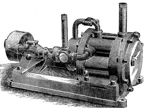
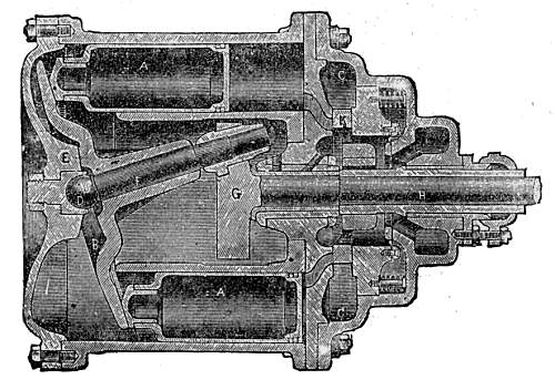
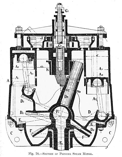 | Left: The Pioneer Axial Engine: 1903
|
These axial steam engines were the forerunners of a number of Axial Internal-Combustion Engines.
![]()

|