
CORNELIUS DREBBEL'S CLOCK: POWERED BY AIR PRESSURE CHANGES
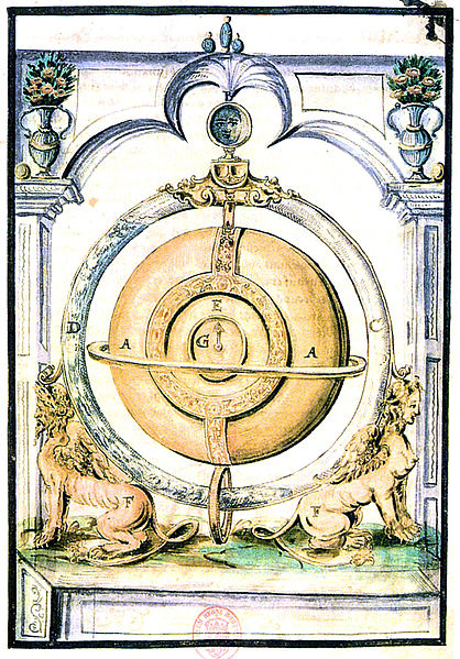 |
| Left: Drebbel's barometric clock: 1610
Cornelius Drebbel- the same remarkable man who is supposed to have rowed a boat underwater up the Thames- built in 1610 a clock telling the time, date, and moon phases. It appears to have been powered by changes in air pressure.
The clock mechanism is contained in the golden casing A in the centre. Around this is a circular tube containing water that is clearly at different levels on each side. The top of the tube appears to have connected to a piston or bellows inside the gold casing which wound a spring.
The mode of operation is somewhat speculative, but some very interesting experiments have been done by H R SantaColoma.
|
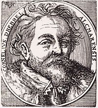 |
| Left: Portrait of Cornelius Drebbel: ca 1631
Looking as though he has just emerged from the pub.
"Alcmarensis" means "coming from or originating in Alcmar". The modern spelling is not Alcmar, but Alkmaar. Thanks to Jonathan Fowler for providing this info.
|
THE DOOR-CLOCK OF THE COMTE D'ONS-EN-BRAY: 1732
"M. d’Ons-en-Bray had created a clock that one winds up without knowing it, by opening the door of the room in which this clock is established."
Clearly a very early example of energy harvesting. Little other information has been found, but Watchmakers and Clockmakers of the World by G. H. Baillie states the clock was made in 1732 at Bercy. In the same spirit, recently electricity has been generated from the physical movement of trees in the wind.
Louis-Léon Pajot, Comte d'Ons-en-Bray (1678-1754) was known for his Scientific Cabinet. He was an honorary member of the French Royal Academy of Sciences.
Source: German Wikipedia
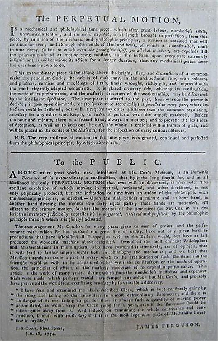
COX'S BAROMETRIC CLOCK: 1760s
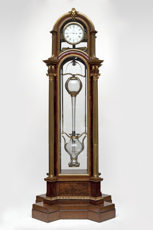 |
| Left: Cox's barometric clock: 1760s
In the 1760s the well-known clockmaker James Cox developed a clock which was were wound up by changes in barometric pressure. The work was done in collaboration John Joseph Merlin, with whom Cox also worked on developing automata. Two large glass vessels containing no less than 68 kilograms (150 pounds) of mercury worked as a massive barometer; they were connected together by an ingenious system of cords and pulleys so that the pulleys would rotate back and forth as the atmospheric pressure and so the glass vessels, rose and fell. A rack-and-pinion mechanism converted this to unidirectional motion so that winding of the mainspring occurred on both rising and falling pressures, and there was a safety-device to prevent overwinding. Cox claimed that his design was a true perpetual motion machine, which of course it was not.
The clock is shown here without mercury in the vessels. This is probably a safety-measure rather than an economy measure; if my calculations are correct filling the clock to get it working again would cost something like Ł600.
Cox was a well-known clockmaker. He showed his self-winding clock in a private museum along with other fine clocks. When he died in 1788, a Mr Thomas Weeks bought the clock for his museum. It stayed in his museum until his death in 1833. It was not included in the sale catalogue of his effects in 1834, and remained lost until 1898 when it was exhibited at the Clerkenwell Institute. After a period on loan to the Laing Gallery in Newcastle, it was auctioned, and finally acquired by the V & A Museum in 1961.
Cox's clock has a Wikipedia page, but it does not give much information.
|
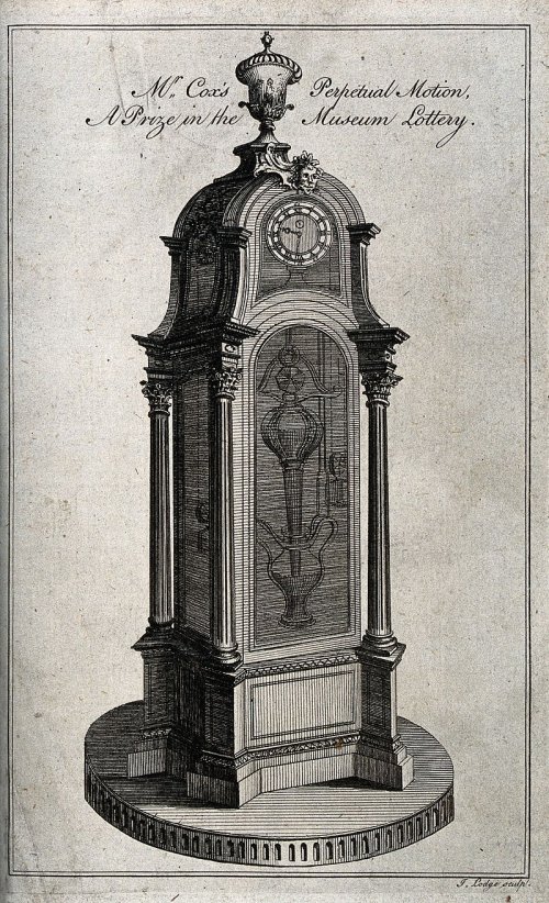 |
| Left: Cox's barometric clock: 1760s
A contemporary engraving of Cox's clock, where it is described as 'A Prize in the Museum Lottery'. Presumably this refers to Cox's private museum rather than that run by Mr Thomas Weeks, as the engraving is dated to 1774. It is not normal for museums to raffle off their exhibits; possibly Cox had despaired of selling it for an adequate sum. Note the confident claim of perpetual motion.
In this view, the driving weights either side of the glass vessels can be seen.
From the engraving, it appears the clock originally had an ornamental urn perched on top, which now seems to be missing; I assert it looks better without it.
Cox's clock is still in the Victoria & Albert Museum in London, but I do not know if it is on display; one of these days I mean to go and find out.
You can see more of Cox's work on the V & A Museum website.
A biographical review of James Cox has been written by Clare Le Corbeiller.
|
 |
| Left: Advert for Cox's barometric clock when it was in Cox's museum: 1760s
After seeing it in Cox's museum, the Scottish astronomer James Ferguson described it as "the most ingenious piece of mechanism I ever saw in my life" (see last line of the text) and contributed to this bit of publicity.
Ferguson was no jobbing hack. He became a Fellow of the Royal Society in November 1763.
You may need to zoom a bit to make it easily readable.
|
LEPAUTE'S AIR-POWERED CLOCK: 1767
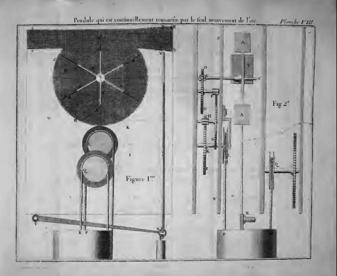 |
| Left: The air-powered clock of M. Jean-Andre Lepaute: 1767
This clock was intended to be rewound by means of air currents in a duct acting on a fan, seen top left in the image. The clock is described in Lepaute's book Traité d'horlogerie (Textbook of Clockmaking) published in 1767.
In the book M Lepaute insists that the difference in temperature between inside and outside a house causes air to rush in through any aperture during the day, and this is sufficient to turn a light fan and keep a clock wound. I have never noticed such air currents. He claims to have installed successful clocks in the Academy of Painting & Sculpture at the Louvre. Perhaps it works if you have a very large enclosed space; did you have to be careful to keep the doors shut?
The fan is at top left in the diagram, with the air duct above it; the air comes in from the right. When the clock is fully wound the rising weight lifts the vertical rod just to the right of the fan, which closes a shutter in the air duct to prevent overwinding.
M.Lepaute has a Wikipedia page. He was clockmaker to the king of France, and so was presumably a competent man.
Many thanks to my correspondent Roland for drawing this machine to my attention.
|
This is a Google translation from the book:
"Description of a Pendulum clock which is continually wound up by the sole movement of the air."
I. The construction of this Pendulum does not differ as to the interior of the movement from that
described above on page 6. but it also contains a crown composed of 3 wheels & a steering wheel, we will give the description.
It is made that the temperature of the outside air is usually different from that of the
apartments that we live in, and which are defended by the thickness of the walls against a
part of the heat or cold which the total mass of the air successively experiences in the
different hours of the day, or in different seasons; so whenever the air
outside is colder & therefore heavier, as it will be, for example,
in the morning before sunrise, the force of its spring and its gravity oblige it to
insinuate itself through the smallest openings that can give it access to places filled with
from a less cold air, consequently less condensed, and which resists less to its action.
In the same way the air which occupies the interior of an apartment being calmer & more peaceful than
outside air, this cannot fail to thread the exits which present themselves outside, and
to penetrate into the interior by the sheer force of its movement.
Ill. From these preliminary notions, it will be easy to understand the effect and usefulness of this
machine; there will be an external opening through which air can enter the
an EESS duct, (Fig. I) by the EE side, & come out SS, in a chimney or outside
from the room; the interior of this conduit will be crossed in all its width by the wings of a
reel BAA, which consequently will be pushed from A to S; every time the
wind from outside or heat from inside will force outside air to enter through
the opening EE; the length of these wings will be approximately 3 inches.
IV. The axle of the reel will carry a pinion C, which will move a wheel DD from D to C, this one
will likewise carry a pinion F which will drive the wheel FG from F to G, finally this one by the
means of the pinion H, will drive the wheel HKI from H to K, & consequently also the pulley L which
is fixed on this wheel, & whose points go up the weight P, by the part LP of the cord,
while this weight by the QR part of the cord acts on the Q pulley of the movement.
V. To prevent the often too rapid & almost continual movement of air, do not
destroyed the machine when the weight, having reached the pulley, could no longer be
go back up; near the external opening EE a valve V has been practiced which is raised
up to T, by means of the XY rocker which is mobile around the point Y, & that the weight
PR obliges to go up when it approaches the pulley Q.
This valve being once reached in T, completely closes the passage of the outside air,
so that it can no longer act on the BA reel, which otherwise would soon be shattered,
as experience has taught me; but as soon as the weight begins to come down, the
rocker YX descending by its own weight, as well as the valve VX, the air passage
becomes free, & the effect of the remontoire begins again.
VI. The air duct that must be practiced for this machine, can be placed behind a
tapestry, or in any other place that will be more convenient, it can be straight or curved,
round or flat according to local circumstances; when it opens into a chimney, it must
be as low and as close as possible to the hearth, lest the sumum enter there.
introduced, it can even then serve as a smoke-repellent, giving the chimney an air that
facilitates the rise of smoke.
VII. We will take care to put an exact separation between the steering wheel & the rest of the machine,
so that the air cannot insinuate itself there; for this effect, we will use a piece of wood or
tinplate ZW which only gives passage to the rod CC of the pinion C, & which separates the flywheel from the
cog.
VIII. This machine is of great convenience in use, experience agrees with
the reasoning; I placed some in various places, among others in the hall of the Academy
of Painting & Sculpture at the Louvre; there is no one who is not charmed to be discharged
forever from the care of rewinding a pendulum, and from the fear of letting it be stopped by
negligence or forgetfulness.
IX. Although mechanical perpetual motion is deemed impossible, one should only be of it.
more attached to asserting the forces of nature in the production of a movement
playful perpetual such as the one we have just seen, or other similar ones that we can
to imagine; I hope to be able to produce the same effect by the gravity of the air alone, which being
variable & as we do, able to balance with a column of Mercury of 29
inches in height, can a fortiori be used to move a machine; I don't know if we've thought about it so far."
|
Lepaute was right about using a column of mercury to derive power from changes in atmospheric pressure; see the Cox clock just above.
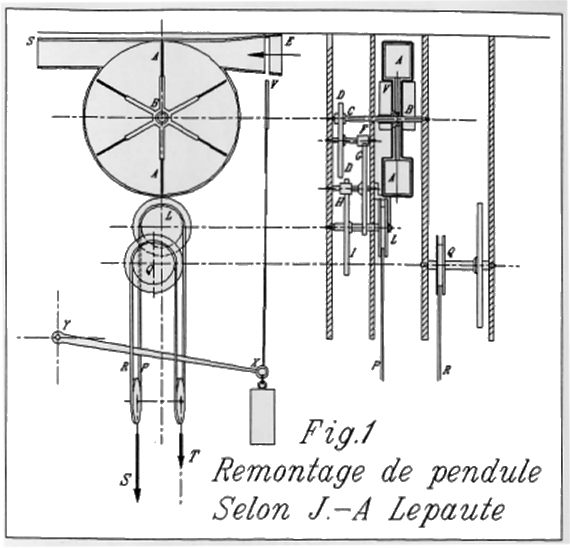 |
| Left: The air-powered clock of M. Jean-Andre Lepaute: 1767
This illustration is rather better than the original one above. Note the differential weight system.
Source: Living On Air: History of the Atmos Clock by Jean Lebet, pub 1997 by Jaeger-LeCoultre
|
ZAMBONI'S ELECTROSTATIC PENDULUM
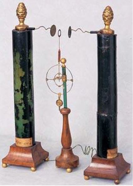 |
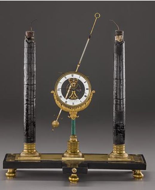
| Left: Zamboni's Electrostatic Pendulum: 1812
This is just a maintained pendulum, not a clock, but it is significant because it the first ever use of electricity to maintain a pendulum. It was devised by Guiseppe Zamboni (1776-1846) who wrote a paper on the dry electric piles that powered it which was published in Verona in 1812.
It is a compound pendulum, the point of suspension being in the centre of the two circles. The Zamboni dry piles are the cylinders at each side. The ring on the upper end makes contact with one of the discs attached to the top of a pile, and so gets a charge of the same polarity as the disc, and the ring is repelled. The swing of the pendulum then takes the ring to contact the other disc (of opposite polarity) and it is repelled again back the other way. The disc is insulated from the rest of the pendulum.
The timekeeping is not very good because the contact with the plates interferes with the free motion of the pendulum. It was constructed by Carlo Streizig, a watchmaker and scientific instrument maker with a shop in Verona, probably in 1814. The use of this principle in actual clocks came slightly later; see below.
Zamboni piles rely only on the moisture of the air to work, and can provide very small currents at high voltage for very long periods without attention. The famous Oxford Electric Bell is a maintained pendulum that has been running since 1840, with occasional short interruptions caused by high humidity.
Zamboni piles have had modern practical use. A three-tube Zamboni pile was used to power British night-vision equipment in World War 2. I bought one many years ago as army surplus, and was disappointed to find it gave out no voltage at all; life can be cruel.
|
ZAMBONI & STREIZIG'S ELECTROSTATIC CLOCK
 |
| Left: Zamboni & Streizig's Electrostatic Clock: 1815
In 1815 Carlo Streizig made an electrostatic clock based on the electrostatic pendulum. As the pendulum swung it turned a 25-tooth crown wheel to which was attached an 8-toothed pinion meshing with a 160-tooth bevel gear that drove the minute hand. From which we deduce that the crown-wheel must have turned 20 times in an hour, the pendulum advancing it 500 times an hour, or roughly 8 times a minute, or once every 7 seconds. A conventional simple pendulum would have to be 12 metres long to beat at that rate, but a compound pendulum as used here can do it compactly; think of a metronome.
In a conventional clockwork clock the pendulum just release the power of the spring or weight; here it drives the clock directly and I suspect that would give poor timekeeping. On the other hand the driving force is pretty much constant over years, and there is no need for fusees or remontoires.
Streizig made these clocks for sale, but how many were sold is unknown. He does not have a Wikipedia page.
|
THE ELECTROSTATIC CLOCK OF FRANCIS RONALDS
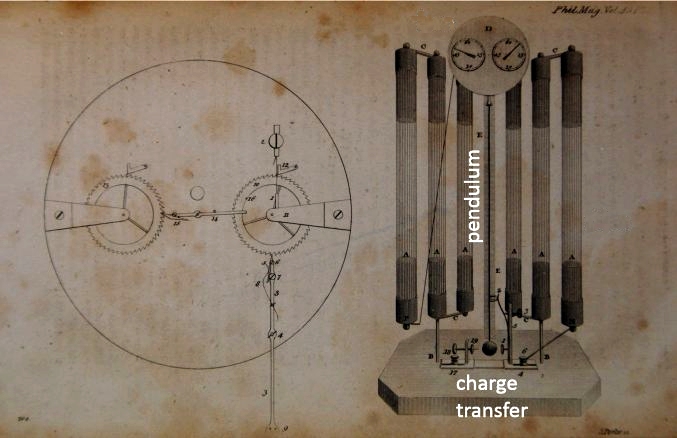 |
| Left: The Clocks Of Francis Ronalds: 1814
Sir Francis Ronalds FRS (1788-1873) began building electrostatic clocks around the same time as Zamboni and Streizig, publishing a design on 9 March 1815 in the Philosophical Magazine.
The clock worked on the same principle, having a pendulum attracted and repelled by electrostatic forces, switched by contacts made by the pendulum bob. The pendulum advanced the clock hands by use of a ratchet wheel.
It was powered by six of Singer's piles with three connected in series for each polarity.
Source: The Philosophical Magazine for 9 March 1815.
|
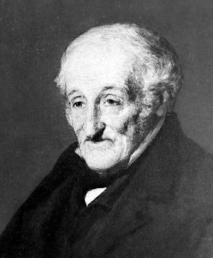 |
| Left: Sir Francis Ronalds
Sir Francis Ronalds FRS had many other interests; at the age of 28, he demonstrated a very early electric telegraph that worked over 8 miles. The proposition was rejected in 1816 by the Admiralty, who famously said it was "wholly unnecessary". This was in the era when optical telegraphs were in use for Admiralty communications. An electric telegraph between London and Portsmouth was not installed until 1845.
Francis Ronalds has a Wikipedia page.
|
THE RAMIS CLOCK
THE ELECTROSTATIC CLOCK OF ALOIS RAMIS
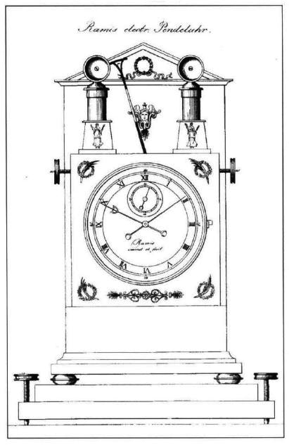 |  |
| Left: The Electrostatic Clock Of Alois Ramis: 1815
Alois Ramis built an electrostatic clock at around the same time as Zamboni and Ronalds; he probably saw the Streizig perpetual Electromotor displayed in Munich, and the suspicion is strong that he copied the idea. Zamboni certainly thought so. Ramis' clock used the same unusual compound pendulum.
The original version is seen in the drawing at far left. The two piles either side of the pendulum look to be much smaller than those used by Zamboni or Ronalds, and the clock seems to have been short on power. The electrodes for attracting and repelling the pendulum also look undersized.
The photograph at left is one of these clocks is in the Munich City Museum, but it has been converted to a spring-wound drive train. The electrostatic drive was clearly not satisfactory.
|
HOURIET'S THERMAL CLOCK: 1820
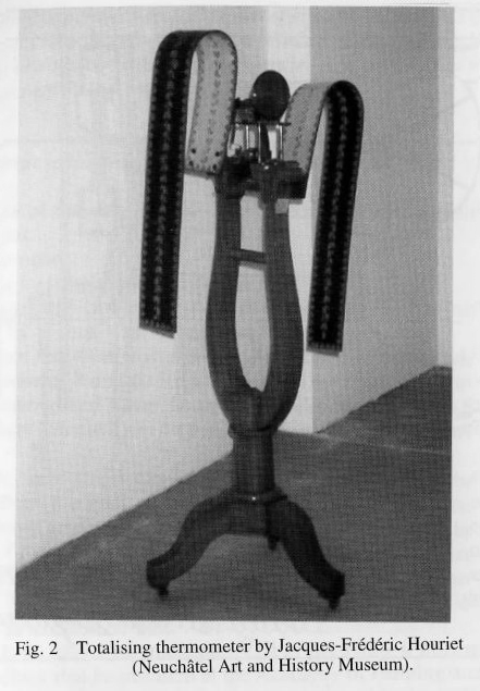 |
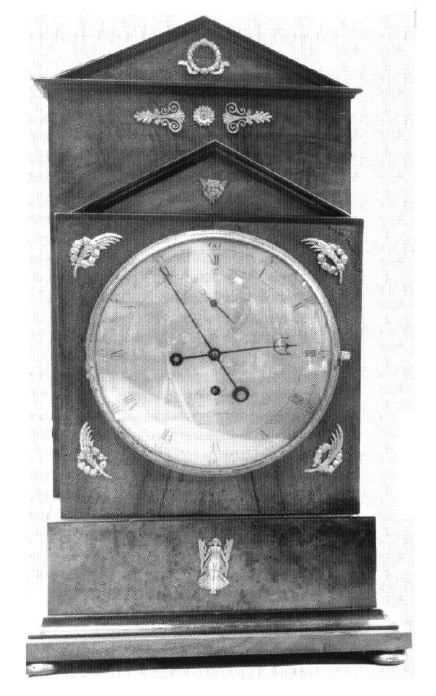
| Left: The thermal clock of M. Houriet: 1820
This is not a complete clock. It was built by Jacques-Frederick Houriet. It was described as a "large scale metallic balancing thermometer to which a clock movement could be adapted and for which it serves as a driving force." The first one was delivered in 1831. The two 'wings' are actually bimetal strips made of iron and zinc; the coefficent of expansion for iron is 12 x 1E-6, while that of zinc is 35 x 1E-6, so the strips bend with temperature changes. One strip has the zinc on the inside and the other on the outside, so as temperature changed the bottom of each strip would move in the same direction and the apparatus would tilt about the central bearing.
Note that this machine is described as a 'totalising thermometer', whatever that is supposed to mean; possibly a summation of temperature changes, though it is not easy to see what use that would be.
Source: Living On Air: History of the Atmos Clock by Jean Lebet, pub 1997 by Jaeger-LeCoultre
|
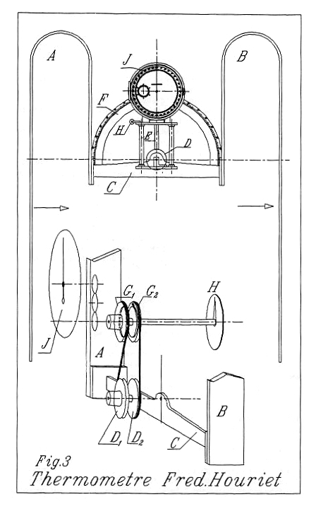 |
| Left: The thermal clock of M. Houriet: 1820
This diagram shows how wheels D1,D2 are turned by the tilting of bar C. Whichever way they turn the wheels G1,G2 turn in the same direction and could be used to wind a spring via a ratchet mechanism.
Once again a very apt name for a clockmaker, and one suspects the hidden hand of nominative determinism.
Source: Living On Air: History of the Atmos Clock by Jean Lebet, pub 1997 by Jaeger-LeCoultre
|
THE CAMERLENGO ELECTROSTATIC CLOCK: 1827
 |  |
| Left: The Camerlengo Electrostatic clock: 1827
At far left is an electrostatic clock built by the Italian Antonio Camerlengo around 1827. It has a temperature-compensating gridiron pendulum beating seconds. The diagram at left shows the pendulum bob moving between two U-shaped electrodes, which looks as though they would apply a good deal more force than the clocks above due the greater area involved. On each side is a Zamboni pile T to provide the power. The voltage on the driving electrodes was switched by an arm on the bottom of the pendulum, though the details are not clear.
The clock train was presumably driven mechanically from the pendulum via a ratchet wheel; the loading on the pendulum would have made for poor timekeeping.
The bottom of the diagram shows a vertical section through the driving electrodes and pendulum bob.
Source of diagram: "Lettera all'Accademia Reale delle Scienze di Parigi", Poligrafo, March 1831
|
THE BIANCHI ELECTROSTATIC CLOCK: 18??
 |
| Left: The Bianchi Electrostatic Clock: 18??
This electrostatic clock is signed Giovanni Bianchi. It is in the Liceo Maffei Museum in Verona, Italy.
There is so far no further information on this clock, but a pendulum can be seen between the two brass plates which drive the pendulum. Presumably there are Zamboni piles hidden inside the wooden base. The plate on the front of the base is not legible.
Google offers several people called 'Giovanni Bianchi' but none are associated with clocks. A Google image search yields nothing.
|
UNKNOWN ELECTROSTATIC CLOCK: 18??
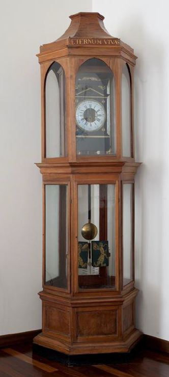 |
| Left: The Unknown Electrostatic Clock: 18??
This electrostatic clock is also in the Liceo Maffei Museum in Verona, Italy. Its maker is unknown.
The lettering at the top of the case says 'ETERNUM VIVAS' which is Latin for 'Live forever'. Clearly the maker was aiming at perpetual motion.
There is so far no further information on this clock, but the two driving plates can be seen below the pendulum bob. Presumably there are Zamboni piles hidden inside the wooden base.
A Google image search yields nothing.
|
THE ANDERVALT HYDROGEN-POWERED CLOCK: 1835
You might think that a hydrogen-powered clock would function by using the gas to run a small internal-combustion engine that would rewind a spring or raise a weight, but a little thought shows that this would be a complicated (and noisy) bit of machinery. Pasquale Andervalt had other ideas...
 |
| Left: The hydrogen clock of Pasquale Andervalt: 1835
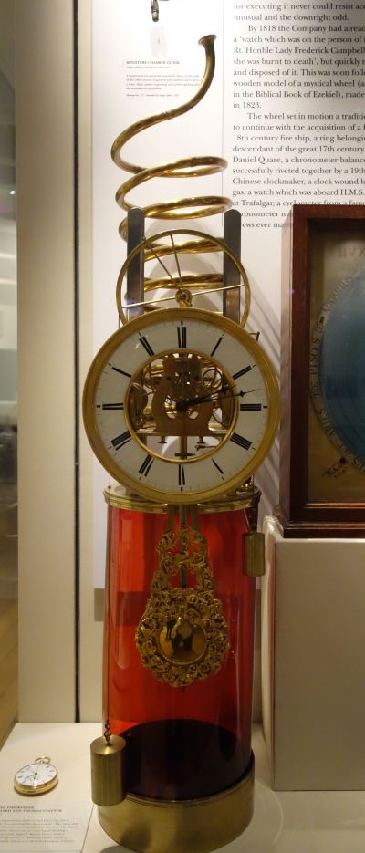
The hydrogen clock was made by Pasquale Andervalt in Italy in about 1835. There seems to be some evidence that several were built, but this is the only known survivor. Very possibly all the others blew up.
The red glass jar contained sulphuric acid. Zinc pellets were stored in the brass spiral above the clock. When a pellet was dropped into the acid, hydrogen was evolved and this pushed up a small piston that raised the driving weight. The clock has a pin-pallet escapement, and the ornate pendulum can be seen in front of the red jar.
The big wheel above the dial has the driving cord running over it, and this wheel was pushed upwards by the piston and cylinder below it, raising the driving weight at bottom left. The smaller weight near the top of the red cylinder at the right simply kept the driving cord taut.
The hydrogen was then presumably released to the atmosphere when a port in the cylinder was uncovered. The clock dropped a pellet automatically when it was running down, and given the large number of pellets that could be stored in the brass spiral, it would presumably run unattended for a very long time. Eventually it would of course be necessary to replenish the pellets and replace the exhausted acid. I imagine the Unique Selling Proposition was something like "almost perpetual motion".
Thus the inflammable nature of hydrogen was not exploited at all. It all seems a bit hazardous- you have a big glass jar of sulphuric acid, and clouds of hydrogen wafting about. If the pellet-dropping mechanism malfunctioned, and dropped all the pellets into the acid at once, there would seem to be a good chance that the clock would explode, sending glass fragments in all directions; followed by a second explosion when the released hydrogen encountered the nearest naked light. One hopes there was some sort of safety-valve.
Carbon dioxide might have been safer as a working fluid- marble pellets could have been dropped into hydrochloric acid. However, in the event of a multi-pellet incident, there might be issues with suffocation. The ideal gas would appear to be nitrogen, but I am not aware of any way to generate it by dropping a solid into a liquid. The standard laboratory method of preparing nitrogen is to heat a mixture of ammonium chloride and sodium nitrite dissolved in water; this evolves ammonium nitrite which is unstable and breaks up into nitrogen and water. Laboratory textbooks warn you to avoid explosions when doing this. (Though they are less clear on how to avoid them) The process does not sound too practical for a clock.
Author's photograph
|
On further thought, what about oxygen as a working fluid? That should be safe enough, unless the concentration in the air becomes high enough to make ordinary materials highly flammable; that seems highly unlikely. So, can we make it by dropping pellets of something into a liquid? One method that suggests itself is dropping pellets of sodium peroxide into ordinary water. This will react "violently or explosively" evolving oxygen and caustic soda, so better make the pellets fairly small. Actually sodium peroxide reacts violently with all sorts of things, and I'm not sure we are heading in the direction of greater safety.
Oxygen can be evolved by dropping manganese dioxide into 6% hydrogen peroxide, but this is a catalytic decomposition and I imagine all of the hydrogen peroxide might decompose at once, bringing back the possibility of an explosion.
Other gases which can be made by dropping solids into liquids are chlorine and sulphur dioxide, but I think the drawbacks there are obvious.
At this point I ran out of innocuous gases, and appealed for anyone with more chemical knowledge than me to suggest a working fluid for this clock that would neither blow you up nor poison you. I received this reply from my correspondent Pigeon:
"In response to your request for comments on possible alternative
working fluids:
As a non-serious suggestion: acetylene, from calcium carbide dropped
into water. The exhaust is not vented, but stored in a reservoir, and
used to feed a little flame so you can still see what time it is at
night. (I am presuming that the working pressure does not exceed 1 bar
gauge, of course.)
Being serious, though, I would definitely plump for carbon dioxide:
unreactive, non-toxic and dead easy to make.
As a suffocation hazard it can be ignored. It is only dangerous in
that regard if there is so much of it that it displaces enough
oxygen-containing air that you can't profitably breathe the result,
which would require a heck of a lot of it. The amount of substance
contained in the clock's curly reservoir tube could not possibly
produce that much CO2 unless both you and the clock were trapped in a
compartment so small that you'd soon breathe all the oxygen in it
anyway.
As far as suffocation hazards are concerned, nitrogen is actually
worse. Both act purely by displacing breathable air, but CO2 will
provide at least some warning that this has happened, because the body
determines how hard it needs to breathe principally by detecting
excess of CO2, not shortage of oxygen. So excess of CO2 in the
atmosphere will cause breathlessness and clue you in that something is
wrong (although in practice the effect is small and it still helps to
be on the alert for it).
Nitrogen, on the other hand, as one might expect since we breathe 78%
of it all the time, produces no warning at all; you just fall over.
There was an incident in the King's Cross area when the Victoria line
of the Underground was being constructed, due to ingress into the
works of air that had percolated down through the clay, losing its
oxygen on the way to reactions with reducing minerals and ending up as
more or less pure nitrogen. As long as construction was actually in
progress there was enough ventilation that this didn't matter, but
when operations were paused for the weekend and ventilation ceased,
the tunnels filled up with nitrogen. Result was that the first blokes
through the door on Monday morning just plain conked out more or less
instantly. Fortunately someone following on was sufficiently with it
to realise what had happened, so they were able to rescue them in time
and without the rescuers suffering the same fate.
And of course CO2 can be produced by the reaction of chemicals so
commonplace and harmless that they can be obtained from standard
kitchen stock. Vinegar and bicarb will do it. Or vinegar and chalk,
for something that conveniently comes as lumps rather than powder.
(Just make sure it's real chalk: blackboard chalk doesn't work,
because it isn't chalk, it's gypsum - calcium sulphate. This was a
source of disappointment to me at school, when I pinched blackboard
chalk out of the classroom and put it into the vinegar pot at dinner,
expecting lots of CO2 and a frothy squirty mess... only to find that
nothing happened at all. Which continued to puzzle me right up until
the internet came along and told me what blackboard chalk really was)"
|
At this stage I questioned. I pointed out that there certainly is such a thing as carbon dioxide poisoning, also known as hypercapnia, though a 10% concentration is likely to be needed to kill. However 7% brings on mental confusion. Pigeon replied:
"...Assuming for the sake of argument that a Total Pellet Release Incident generates 100 litres of CO2,
to achieve a 10% concentration would require that both you and the
clock were shut in a cabinet so small as to leave only 1 cubic metre of
unoccupied volume, which would not be a situation you'd willingly get
yourself into in the first place. To generate 100 litres of CO2 at STP
requires about 400g of calcium carbonate; guesstimating from your
photo I'd reckon the capacity of the coiled tube, in terms of pellets
of chalk, is of that order, so I still think we're safe."
|
I am convinced. Carbon dioxide it is.
The clock is currently on display in the Science Museum, London. The clock was presented to the Museum of the Worshipful Company of Clockmakers by William Wing in 1874. The only William Wing known to Google was an entomologist who died in 1855, so the donor is currently mysterious.
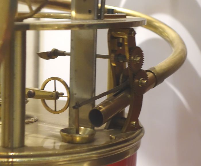 |
| Left: The hydrogen clock of Pasquale Andervalt
This picture is an improvement on the one here before. It shows at bottom centre, just beyond the end of the pipe, the critical valve that drops zinc pellets into the acid. (Unfortunately it is hard to get sharp pictures through glass) There is a round port into the jar, closed with a disc which is presumably pressed up against its seating when there is pressure in the jar.
Further back up the pipe there is some sort of geared mechanism for releasing pellets one at a time, but its details are not clear. This mechanism is triggered by the lever (seen just above the spoked wheel) when the carriage holding the big wheel descends.
The spoked wheel is one of the four guiding wheels for the up and down movement of the carriage.
Author's photograph
|
THE HOARD AIR-WOUND CLOCK: 1860
 |
| Left: The Hoard clock: 1860
This clock is wound by air currents, in the same way as Lepaute's air-draught clock of 1767.
Nothing very original here, except the fan is now an axial type. Presumably the US patent office did not know about Lepaute. Hoard suggested an opening in a wall might be used instead of a flue, or the fan placed on top of the house winding a clock downstairs by pulleys or shafts.
The same Hoard patent appears to have been taken out in England. The text of the patent is given in English Patents of Inventions, Specifications: 1860, 1226 - 1271 and a rather crude drawing that is essentially the same as that in the US patent is attached. Mr Hoard and his clock are otherwise unknown to Google, so it can be assumed his idea failed to thrive.
Source: US patent 27,721 April 1860
|
THE HITCHCOCK AIR-WOUND CLOCK: 1861
 |
| Left: The Hitchcock Air-Wound clock: 1861
This is another clock intended to be wound by a wind turbine. Figure 2 shows the clock-case A with turbine B inside it; the clock is meant to be built into the wall of a chimney or flue. Presumably not one with a fire at the bottom. The turbine directly acts on a 'weak and sensitive mainspring' in case D. Mr Robert Hitchcock does not seem to very optimistic about the amount of power available.
I suppose you might call it a Hitchclock.
Hitchcock took out at least two more patents; US Patent 33250 Clock Self Wind, Robert Hitchcock 10 Sep 1861, and Patent 37397, 'Winding Clocks by Currents of Air'.
Source: US Patent 31,242
|
 |
| Left: The Hitchcock Air-Wound clock: 1863
This is a development of the design above. There are now two four-bladed fans (described as 'flutter wheels') on the shaft, indicating the first version was somewhat short on available power.
It is another Hitchclock.
Source: US Patent 37,397
|
THE HORSTMANN CLOCK: 1866
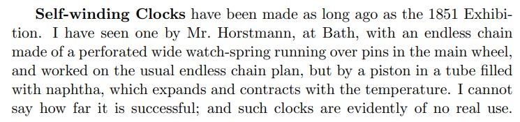 |
| Left: The Horstmann clock: 1866
Hortsmann's clock is powered by the expansion and contraction of naptha. Why it is evidently of no real use is not told to us here, but apparently the clocks were unreliable due to leakage of the working fluid. Not a good thing if it's inflammable. Be aware that Lord Grimthorpe was considered an an awkward and argumentative person.
Horstmann's clock is known to Google, but you have trouble sifting through contemporary time-switches made by Horstmann. Yes, the same company.
Source: A Rudimentary Treatise On Clocks, Watches, & Bells For Public Purposes by Lord Grimthorpe, Van Nostrand 1903
|
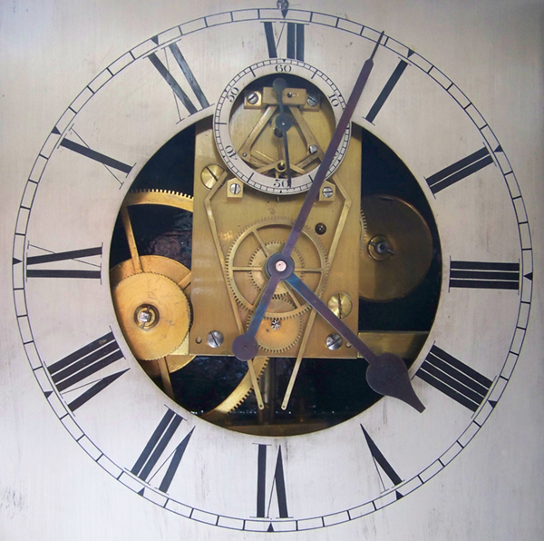 |
| Left: The dial of the Horstmann clock in the Bath Newseum: 1866
Further research has been done. Three wall mounted clocks were made, each to a different design, by Gustav Horstmann in the 1860s to demonstrate his heat driven ‘Thermo-automotor’ invention which could be used to automatically wind a clock. The Bath museum holds one of these clocks (recently restored to working order) and the two others are in private hands. Horstmann never seems to have been concerned about marketing his clock or its mass production; it was more of a tour-de-force.
Read more at the Bath Newseum site.
There is a video of the clock running here. The escapement is clearly the Double Three-legged Gravity Escapement invented by Bloxam and later improved by Lord Grimthorpe. It is used in the Big Ben clock.
|
 |
| Left: The internals of the Horstmann clock: 1866
The tank of expandable and inflammable fluid is at the top, and it looks as though it holds quite a lot; enough to make any householder nervous. The fluid works on a piston A at bottom right of the clock case; glycerine was used as some kind of sealant but appears not to have been very effective. The piston pulls on the cable going over pulley X and this is transferred to the winding mechanism of the differential weight system. This is said to have wound the clock on both rising and falling temperatures, though exactly how this worked is obscure. Fig 3 on the right apparently shows the mechanism but gives little clue how it worked; the function of the horizontal rack is unknown.
Source: Bias Journal No 27, 1994, reproducing British patent No 2353 of 1866
|
 |
| Left: The Horstmann clock patent: 1866
Here we learn that the purpose of the glycerine was to prevent evaporation of the volatile naptha.
Source: Specifications of Inventions, published by the Great Britain Patent Office, Record 1: 1617-1875, Volume 9, Issues 652-760. No drawing is attached.
|
 |
| Left: The Horstmann clock patent: 1866
This gives the patent number as 752, not 2353. Horstmann may have taken out two patents, but note this is just a provisional patent.
|
 |
| Left: The Horstmann clock patent: 1866
The letters here do refer to Figure 2 in the diagram above.
This gives the patent number as 752, not 2353. Horstmann may have taken out two patents, but note this is just a provisional patent.
|
 |
| Left: The Horstmann clock patent: 1866
Figure 3 above is an alternative way of winding a clock and is not part of Figure 2.
This gives the patent number as 752, not 2353. Horstmann may have taken out two patents, but note this is just a provisional patent.
|
THE BEVERLY CLOCK: 1864
 |
| Left: The Beverly Clock: 1864
The Beverly Clock is displayed in the foyer of the Department of Physics at the University of Otago, Dunedin, New Zealand. It is powered by changes in barometric pressure, and more importantly temperature, acting on a 1 cubic-foot box of air which presses on a diaphragm and raises the clock weights, presumably by some sort of ratchet mechanism. A temperature variation of 3.3 degC over a day gives enough power to raise a one-pound weight by one inch.
The clock was built by Arthur Beverly in 1864. The clock has, like the Atmos described below, a torsional pendulum with a very slow period that requires very little power to keep it working; torsional pendulums are used in so-called "400-day" clocks. The Beverly Clock occasionally stops if the ambient temperature has not fluctuated enough.
|
BERNARDI'S ETHER-POWERED CLOCK: 1875
 |
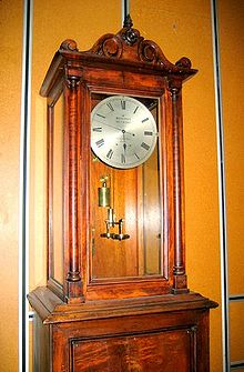
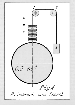
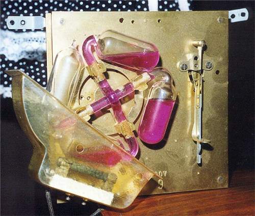
| Left: The ether-powered clock of M. Henri Bernardi: 1875
This clock is powered on the same principle as the drinking bird. The arrangement of bulbs and pipes contains ether, and since the word is not qualified it is presumably diethyl-ether, which boils in the bulbs immersed in water. The bulbs are covered with a fabric net, and are cooled by evaporation when exposed to the air. This condenses the ether in the bulbs, unbalancing the wheel and causing it to rotate.
The obvious snag here is that diethyl-ether (CH3CH2–O–CH2CH3) does not boil at normal room temperatures; it boils at 34 degC at standard atmospheric pressure. Dimethyl-ether (CH3–O–CH3) boils at -23 degC so apparently that won't work either. However, the drinking bird normally uses methylene chloride which boils at 40degC. The answer to this conundrum seems to be that the pressure in the bulbs is below atmospheric, so the boiling point is reduced; it can be adjusted to be very near normal ambient temperature by controlling the amount of pressure reduction. Methylene chloride is safer than diethyl-ether because it is neither flammable nor explosive in air; however it is a neurotoxin and very probably carcinogenic, so I'd stay away from it.
The La Nature article claimed that a clock on this principle had been running for two months in the laboratory of M. Bernardi, without renewal of the water. The machine has about it a distinct air of Perpetual motion but it is of course no such thing. It is driven by the temperature difference between the bulbs in the water trough and the evaporation-cooled bulbs in the air, working as a Carnot Engine. The temperature difference is very small so the efficency is very low, though I'm not sure how the efficiency would be defined. I don't feel that gets to the ultimate source of the power, and I would be glad to hear any opinions on the subject.
There is a similar unsatisfactory situation with the Crooke's Radiometer. I have one of these and it undoubtedly works, but how it works has been much debated.
Bernardi has a Wikipedia page, but it does not mention his ether motor.
From article in La Nature 1875, p80
|
This is translated from the La Nature article:
"A NEW ENGINE
According to the laws of the mechanical theory of heat, mechanical
work can be produced by the use of any difference of heat. The
solution of the problem of the production of work, obtained according
to this principle, was sought in the following way by an Italian
physicist, M. Henri Bernardi:"
"Two similar glass flasks are connected by a thin tube, also made of
glass. The ends of this tube pass through the flasks with a
rectangular bend. One of these flasks contains a small tube which
makes it possible to introduce ether into the apparatus. The ether is
brought to boiling, and when all the air has been expelled, the tube
is closed using a torch. * The quantity of ether contained in the system
must be such that it fills three quarters of a flask. In the middle of
the connecting tube there is a part through which passes a metal axis,
on which the whole system can turn. When the ether is equally shared
between the two flasks, the device is in an unstable equilibrium. The
axle supports sit on top of a rectangular box, which has a slot
through which the rotary system passes."
"The crate is full of water, into which the flasks plunge alternately
in this rotational movement. Each flask is covered with a very fine
trellis. It is easy to understand that this device adopts a circular
motion."
"Due to the unstable equilibrium of the system, one of the flasks,
which we will call A, descends carrying all of the ether, while the
rest of the space is filled with vapour. The flask A is thus in the
water, and the other flask, which we will call B, in the air. The thin
layer of water spread over B begins to evaporate, which cools the
container and consequently condenses the vapour. The ether thus
condenses in B, until finally B contains more ether than A, and
plunges in its turn, A rising again. And so on. This circular movement
only stops when there is no more water in the box to moisten the
surface of the lowered flask."
"It would be difficult to mechanically take advantage of this
thermo-engine. Also, Mr. Bernardi has modified his device in the
following way: the two flasks or balloons described above are
connected by a tube whose ends are bent (at right angles) in opposite
directions. Three similar systems form a kind of wheel, and the
centers of the six balloons are with the tube in the same plane. This
wheel is supported on an axle, which presses against the lid of a
rectangular box, in such a way that, in its rotation, it always has
one half submerged and another emerged."
"The balloons are covered with a trellis and the crate contains just
enough water for a single balloon to be completely immersed in it.
Starting the engine by one turn of the wheel, a continuous rotation is
obtained, and through a suitable set of pulleys the wheel can lift a
weight or do other work."
"A similar thermo-motive wheel has been running a clock in M.
Bernardi's laboratory for two months. The balloons are 0.78 inches in
diameter, the center to center distance is 3.1 inches, and the amount
of ether in each system fills three quarters of a balloon. The clock
that this wheel keeps moving is shown above. The water level, by a
special arrangement, is maintained at the same height. Mr. Bernardi
was able to operate his wheel for three months, without renewing the
water or cleaning the balloons. He calculated the quantity of heat
displaced by this device and taken from the surrounding environment:
it is equivalent, in 24 hours, to 60 wheel movements or revolutions,
which are worth half the work consumed in the same time by the clock. **"
|
* "The ether is brought to boiling, and when all the air has been expelled, the tube is closed using a torch."
I would have though that would be very hard to do without blowing up both the apparatus and yourself. It also gives no hint as to how a carefully controlled pressure below atmospheric could be established in the tubes.
** "He calculated the quantity of heat displaced by this device and taken from the surrounding environment: it is equivalent, in 24 hours, to 60 wheel movements or revolutions, which are worth half the work consumed in the same time by the clock."
This statement is puzzling, for it seems to say the thermal engine only generates half of the power required to run the clock.
Two vital facts are missing from the above account: how much torque does the motor deliver and how fast does it go round? Drinking birds have in my experience a cycle time measured in minutes as water evaporates slowly.
THE AUTODYNAMIC CLOCK OF FRIEDRICH RITTER VON LÖSSL: 1880
 |
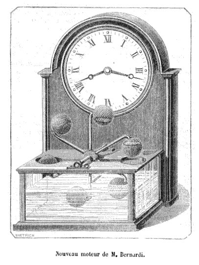
| Left: The principle of the Lössl Clock: 1880
Both air pressure and temperature variations affect the force on the stacked bellows units at the top of the tank. There was a pressure-release valve to prevent overstressing of the bellows. In actuality the clock used multiple spring-barrels to store energy, rather than a weight.
The volume of the tank was 0.5 m3. If it was spherical, it would have been just under a metre in diameter. (98 cm)
|
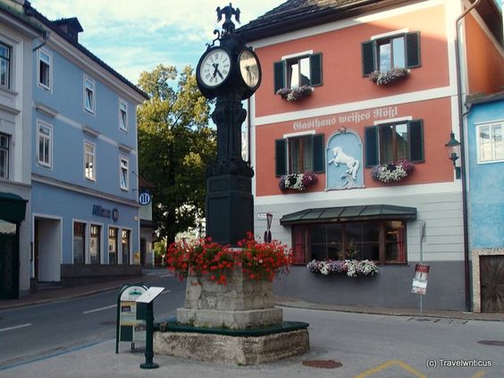 |
| Left: The Lössl Clock at Bad Aussee, Austria: 1880
This is the last remaining Lössl clock in the world. It has been standing at Bad Aussee since 1897; before that the clock stood in Vienna but was removed to make room for the building of Vienna's city train network.
The conical 0.5 m3 tank was inside the iron pedestal at the bottom. I have read in several places that in later years traffic vibration affected the rewinding mechanism, and so the clock was converted to electrical winding. It seems to me more likely that it was the clockwork that was affected, and the whole mechanism replaced by an electric clock.
|
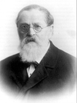 |
| Left: Friedrich von Lössl (1817-1907)
He has a Wikipedia page in German.
Lössl’s workshop was in Vienna (Währing), at AnastasiusUGrünUGasse 35. The first autodynamic clock was erected on 18th September 1880 in the Wiener
Cottagegarten (today Türkenschanzpark), and more followed in the City Park (1881) and in the Prater. (1883) In the following years
new clocks were manufactured and positioned in Vienna in the Währinger Gürtel (1888) and in the Hernalser Hauptstraße (1891).
In 1904 the clock manufacturer Alfon Schauer took over the patent rights for the autodynamic clock
system from Lössl. Clocks were erected in the children’s playground in the City Park (1904) and in the Maria-Josefa
Park in 1905. (Now Schweizergarten)
In 1905 the clock in the Hernalser Hauptstraße was bought by the city of Vienna. Lössl’s clocks (probably not more than fourteen in total) were exported to Linz, Paris, Hamburg and Marburg.
|
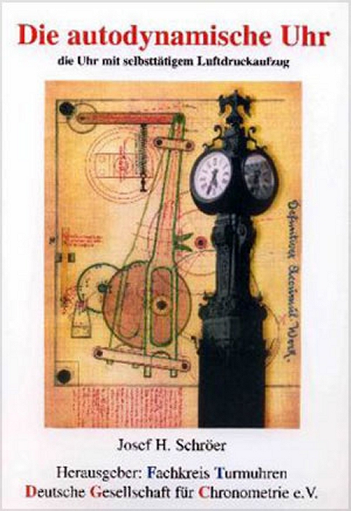 |
| Left: The book of the clock
A book was written on the system in 2003; Die autodynamische Uhr des Friedrich Ritter von Lossl, die Uhr mit selbsttatigem Luftdruckaufzug (Friedrich Ritter von Lossl's autodynamic clock, the clock with automatic air pressure winding)
Authors: Josef H. Schroer, Deutsche Gesellschaft fur Chronometrie. Print Book, German. Publisher: Gunter 2003
The cover presumably shows part of the clock mechanism, but it is not clear what it does.
|
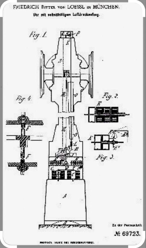 |
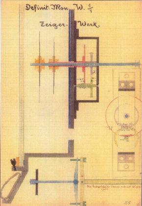
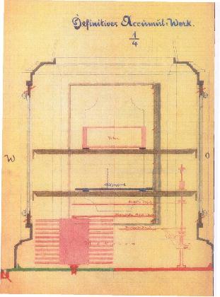
| Left: The von Lössl patent 69723: 1880
This image is unfortunately not of good quality. At the base is the conical air reservoir A. On top of it are two bellows C, and just above that is the clock mechanism, with its axles F set vertically. The hands were driven by a vertical shaft and right-angle gears.
Lössl's clock was unusual in having a conical pendulum. This uses no escapement but allows the clock to move continuously rather than in steps. There is also a Wikipedia page on the conical pendulum.
Lössl received the patent from the Imperial Patent Office on 28 October 1880.
|
 |
| Left: The motion-work of the clock
The motion-work of a clock is a 1:12 reduction of the minute hand speed to drive the hour hand. The use of four gears is conventional.
Source: Wikimedia Commons
|
 |
| Left: The air-motor of the clock
You can see the metal bellows (or at least one of them) but unfortunately there is very little information here.
Source: Wikimedia Commons
|
FRENCH ALCOHOL CLOCK BY CHARLES HOUR: 1902
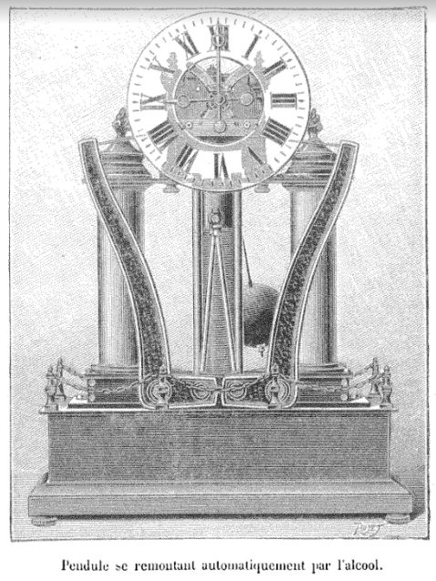 |
| Left: The French Alcohol Clock by Charles Hour: 1902
This thermal pendulum clock was invented by M. Charles Hour; surely no clockmaker was ever more aptly named, and one might suspect the hand of nominative determinism.
The clock was wound by the thermal expansion of alcohol, responding to changes in the ambient temperature. The alcohol was contained in the two columns on each side, which were made of copper, presumably to speed thermal transfer. The details are not yet translated, but the expansion of the alcohol was amplified by the two curved levers, which wound up the clock via steel ribbons. Ethanol has a volumetric expansion coefficient of 0.00109 per degC, about five times that than water at 0.000214 per degC. Somewhat better again is ether at 0.00160 per degC, but we're trying to make a clock, not a time-bomb.
Ether seems to be the most expansive of the common liquids, unless you count Dichlorodifluoromethane refrigerant (R-12) which has 0.0026 per degC. However the manufacture of the latter is banned as it plays havoc with the ozone layer.
The caption says: "Clock that rewinds itself automatically with alcohol"
Many thanks to my correspondent Roland for drawing this machine to my attention.
Source: La Nature 1902, Trentičme année, premier semestre: n°1489 ŕ 1514
|
On another page, I explore the possibilities of using the thermal expansion of solid rods to wind up a clock; I think it is entirely practical, if possibly cumbersome.
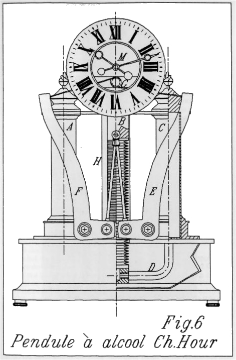 |
| Left: The French Alcohol Clock by Charles Hour: 1902
This drawing gives more information on how the clock worked.
A and C are the two columns filled with alcohol, communicating with bellows H via the pipe D. The use of bellows rather than a piston and cylinder should eliminate any leakage of the working fluid; bellows were also used by Lossl and are used by the Atmos clock. It seems the obvious method (once the technology to make metallic bellows exists) and it is odd that so many inventors chose to use a piston and cylinder.
The two narrow rods push or pull on the bottom arms of the right-angle levers F and E. There upper arms pull on steel ribbons which were wound on a roller G. It is not clear if the clock is wound on both rising and falling temperatures.
The levers F and E seem unecessarily massive, and do not make for a handsome look, but this strikes me as the most practical of the early self-winding clocks.
Source: Living On Air: History of the Atmos Clock by Jean Lebet, pub 1997 by Jaeger-LeCoultre
|
 |
| Left: The French Alcohol Clock by Charles Hour: 1902
This drawing gives more information on how the clock worked.
|
 |
| Left: The French Alcohol Clock by Charles Hour: 1902
This is a side view of the Hour clock.
|
 |
| Left: The French Alcohol Clock by Charles Hour: 1902
This drawing gives some more information on the winding mechanism.
|
FRENCH WATER PRESSURE CLOCK: 1914
 |
| Left: The French Water Pressure Clock: 1914
According to Popular Mechanics for April 1914: (p552) "The variations of pressure in the water mains are utilised by a French inventor for the operation of a self-winding clock." And that's all they wrote.
Presumably there was a spring-loaded piston, or equivalent, that moved as the water pressure varied with the daily demand cycle; that should provide plenty of power to wind up a clock. Whether it would work with modern water supplies, which one imagines would have good pressure regulation, is another matter. I have not been able to find any data on water pressure variations. Can anyone help?
In Paris this invention would have had to face severe competition from the pneumatic clock network, which distributed time over a large area.
Google has nothing on this.
|
CORNU'S THERMAL CLOCK: 1920
 |
| Left: Cornu's Thermal Clock: 1920
(1) The heat from the burner vaporises the liquid in bulb B and the pressure drives the liquid into bulb A, causing the arm to tilt. (2) At the same time a cover is moved over the burner so B is no longer heated. It cools, reducing its internal pressure, and counterweight P returns the arm to its initial position. The see-saw action of the arm winds up the clock through a ratchet R.
This does not impress; it is hardly convenient or economic to keep a lamp burning continually just to wind up a clock. Furthermore, the heat is completely wasted for half of the cycle. This idea appears to have got nowhere and I can't say I'm surprised.
|
MEIER'S THERMAL CLOCK: 1926
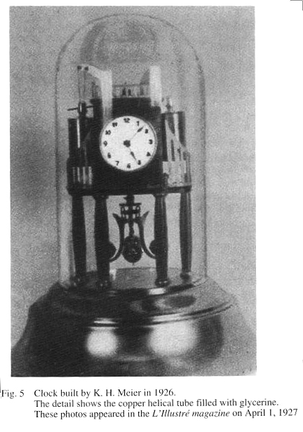 |
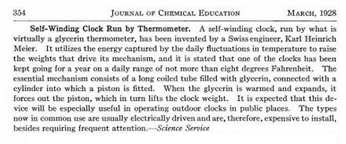
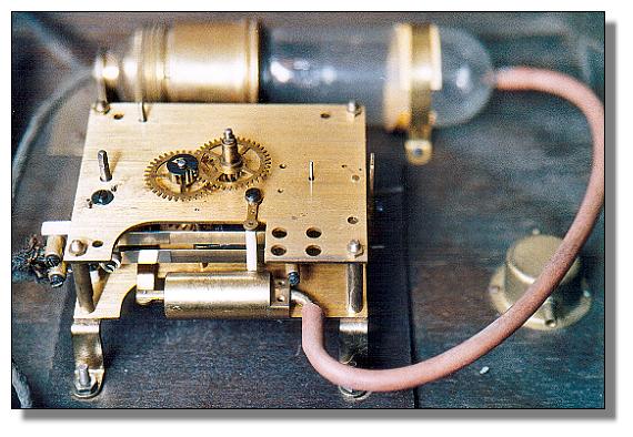
| Left: Meier's Thermal Clock: 1926
This clock was invented by Karl Heinrich Meier of Ruschlikon in Switzerland. It was wound by the expansion of of glycerine in two coiled copper tubes; the coiling was presumably to increase the surface area and so speed the response to ambient temperature changes. The expanding glycerine drove a piston when the temperature rose and wound the clock. Glycerine has a thermal expansion coefficent of 5 x 10⁻⁴, while alcohol has 10.8 x 10⁻⁴. It is not known why Meier chose glycerine rather than alcohol; perhaps being viscous it was less likely to leak. The durability of the clock obviously depended on the piston and cylinder not leaking.
The details of the rewinding mechanism are not currently known, nor is it known if the rewinding occurred for both rises and falls of temperature.
There does seem to be an obvious problem here. The entire clock, incuding the glycerine tubes, is inside a glass dome which will much reduce the temperature variations inside it.
Source: Living On Air: History of the Atmos Clock by Jean Lebet, pub 1997 by Jaeger-LeCoultre. This gives an incorrect explanation, saying that the distortion of the coils was used for motive power.
|
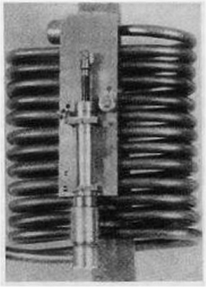 |
| Left: Meier's Thermal Clock: 1926
The coiled tubes of glycerine; the piston and cylinder can be seen at the front.
Source: Living On Air: History of the Atmos Clock by Jean Lebet, pub 1997 by Jaeger-LeCoultre
|
 |
| Left: Meier's Thermal Clock: 1926
This tells us that Meier was Swiss and gives some more details.
Meier was clearly interested in alternative ways of winding clocks. In 1927 he was awarded a German patent for "Automatic winding up by movements of other objects, e.g. by opening a hand-bag, by opening a case, by opening a door; Winding up by wind power by rotating axles, e.g. tachometers."
Searches on the career of Meier are not helped by the short career of a Dutch spy also called Karl Heinrich Meier
Source: Journal of Chemical Education March 1928
|
JUNGHAN'S ELECTRONOME: 1927
 |
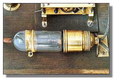
| Left: The Junghans Electronome: 1927
The Junghans Electronome clock was powered electro-pneumatically; the glass bulb in the background contained a heating element which caused the air in the bulb to expand. The increased pressure passed through a rubber hose to moved a piston in the brass cylinder in the foreground, which wound up a conventional clockspring. The bulb was switched on and off once a minute by cam-operated contacts.
Junghans acquired the patents for pneumatic clocks, dated 1927, from the inventor, Martin Fischer of Zurich. The clocks were distributed in Germany by Junghans under the name "Elektronome"
The four gears on top of the clock are what is usually called the motion work. It is a 12-1 reduction gear train that drives the hour hand from the minute hand. It is joined to the going train of the clock by friction coupling from the cannon pinion, so both hands can be turned by hand to set the time. It is usually outside the front plate of the clock, and beneath the dial.
|
 |
| Left: The Junghans Electronome: 1927
The 'kolben' (piston) has a helical spring under it to return it when the air cools.
The pressure generated was sufficent to operate up to six slave clocks with their own drive cylinders. The minute contacts could be used to switch another six electrical slave clocks.
No dropper resistor or suppression capacitor is shown.
|
 |
| Left: The Junghans Electronome: 1927
This shows the clock in its vertical operating position. The power comes in at top left. At top right is a dropper resistor, which looks to be adjustable for differing mains voltages. On the right is the compressor lamp. The round thing at the bottom is a multi-way adapter for the compressed air; it is not connected here.
|
 |
| Left: The Junghans Electronome: 1927
The air-heating bulb.
|
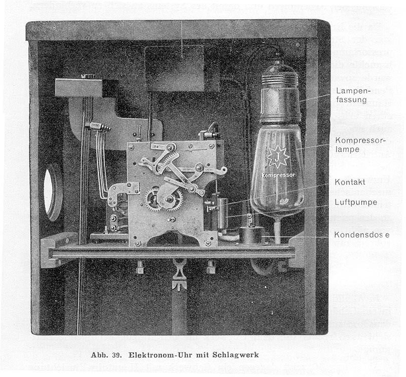 |
| Left: The Junghans Electronome: 1927
This shows a striking version of the clock with four different hammers and chime rods. The 'luftepumpe' (it is not a pump) is the cylinder with the piston moved by the expanding air. The kondensor (capacitor) was presumably connected across the contacts to prevent radio interference.
Note the 'J' for Junghans on the air-heating bulb.
|
The word Electronome seemed familiar. As a lad I was an enthusiastic reader of Angus MacVicar's Lost Planet series. There the Electronome was a machine that facilitated telepathy. I wonder if MacVicar had a German clock?
 |
| Left: The Junghans Electronome: 1927
This gives a better idea of the working of the clock. It looks as though when the air cooled the piston was returned to its starting position by gravity. The rewinding is said to be "almost without noise". You can see a Junghans Electronome operating on YouTube; there are various gasping noises on the soundtrack, but apparently this is not the clock working as the bulb is said to be broken.
Presumably there was some leakage past the piston, which might well not be symmetrical for pressures above and below atmospheric; if so there seems a danger that the amount of air contained in the system would tend to either increase or decrease. If precautions were taken to limit this, they have not emerged so far.
Note the reference to Fischer's patent 631,327, though it is not stated in which country the patent was taken out.
Source: Les horloges de commutation ŕ mouvements mécaniques remontés électriquement by Lavet M, from Annales Francaises de Chronometrie, Vol 19, pp175-197, 1949
|
THE PUJA THERMAL CLOCK
 |
| Left: The back of a Puja clock made by the German firm of Jauch and Schmid: 1940
The notion here is to power a clock reliably when faced with mains electricity of uncertain voltage and frequency. It is perhaps significant that the patent for the principle (No. 714,893) was granted in Germany in 1940. It would work from either AC or DC mains. In Britain AC and DC coexisted for some time; I am not sure if that was the case in Germany; but judging by the advert below it was, and the mains could be either 110V or 220V.
At the lower left, shielded by a translucent housing, is a carbon rod resistance that heats the coloured alcohol in the glass vessel just above it. This causes some of the alcohol to vapourise, the pressure pushing the liquid up the connecting pipe to the vessel at top right. As the latter gets heavier the wheel bearing the four vessels experiences a torque that rewinds a remontoire* spring driving a conventional gear train and escapement. This clock has a pendulum-controlled escapement, but models with balance wheel escapements also existed.
The firm of Jauch and Schmid was registered in 1930
The images in this section were very kindly provided by John Howell.
|
*A remontoire, from the French 'remonter' (to rewind) is a spring or gravity reserve of power that can be configured to give a near-constant driving torque because it is rewound at frequent intervals from another power source- usually this was a mainspring, whose own torque would slowly decrease as it unwound. The idea was that rewinding a spring or lifting a weight at relatively frequent intervals isolated the escapement from the variable torque of the mainspring.
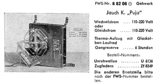 |
| Left: Advertising material for the Puja clock movement.
The clock shown here has a balance-wheel escapement attached instead of a pendulum.
|
To save you the trouble of grappling with a German-English dictionary, here are the translations of the salient words in the advert above; "wechselström" means "alternating current", "gleichström" means "direct current", "thermo-aufzug mit glaskolben-laufrad" translates as "thermo-lifter with glass bulb impeller", and "gehwerk" as "movement".
Gangreserve 6 stunden = power reserve 6 hours. Unruhwellen = balance shafts, and zugfedern = tension springs. I'm not too clear what the last two words are getting at; it looks like two different models, and perhaps refers to pendulum and balance-wheel versions.
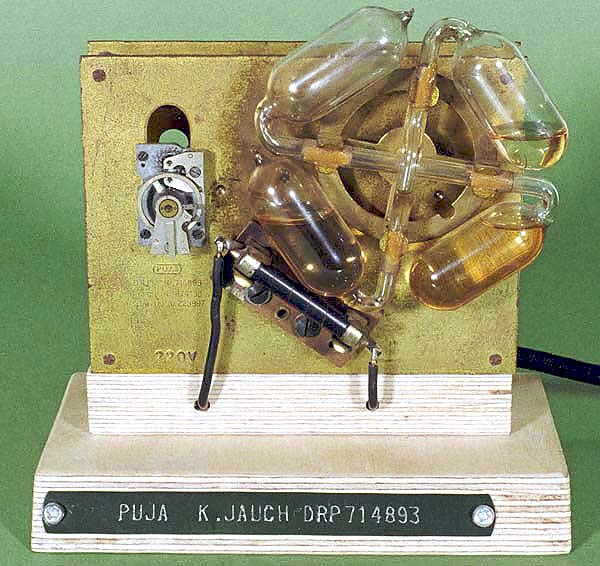 |
| Left: Another Puja clock movement
This clock also has a balance-wheel escapement attached over a hole where the pendulum would go.
It occurs to me that this arrangement must be very inefficient; it looks as though much of the heat would escape without doing anything useful. Presumably the translucent trough shown in the first picture helped to keep the heat in.
I also wonder if the Puja clocks were prone to catching fire.
This model is for 220V mains.
|
 |
| Left: Another Puja clock movement
This is a different clock, with differently-coloured alcohol and a neater escapement mounting. A modern wire-wound resistor has been fitted into the heater spring clips.
|
THE ATMOS CLOCK: POWERED BY TEMPERATURE AND AIR PRESSURE CHANGES
Anyone interested in oddly-powered clocks will have heard of the Atmos clock, which appears to be mostly powered by changes in temperature, and not, as its name might suggest, solely by changes in atmospheric pressure. A flexible metal capsule is filled with an inert gas and a little ethyl chloride, which vapourises as the temperature rises, causing the bellows to expand, and vice versa. A chain transfers this movement to wind the mainspring. A torsional pendulums with a long period is used to minimise the power required.
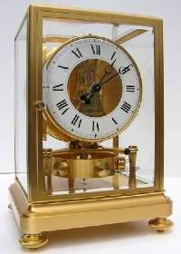 |
| Left: An Atmos clock
A temperature variation of only one degree in the range between 15 and 30 degrees Celsius, or a pressure variation of 3 mmHg, is said to be sufficient for two days' operation. I don't know if it is the case, but that seems to imply that the clock would stop working if the temperature fell below 15 degrees and stayed there, with the ethyl chloride remaining liquid. This is of course very possible in Winter. I also wonder how it copes with thermostatically-controlled central heating.
The torsional pendulum makes only two oscillations per minute, which is 1/60th the rate of the standard seconds pendulum in a conventional clock. Because of the very slow movement of the gear train, no oil is used; it is claimed no measureable wear occurs.
|
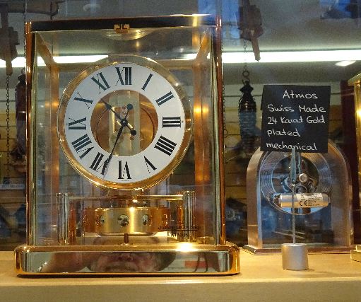 |
| Left: An Atmos clock not running in Bern: 2025
I saw this Atmos clock in a shop window in Bern, Switzerland, on 22nd July 2025. It looks very much like the picture just above.
But the important thing was that IT WAS NOT RUNNING. The torsion pendulum was stationary. I thought that the whole point of Atmos clocks was that they kept running without outside help. Possibly it had been stopped to avoid wearing out the mechanism, but surely a very expensive clock would only wear out at an extremely low rate.
No price was displayed and I didn't have time to go in and ask. Looking at the Net, it seems a price around Ł15,000 is likely. Expensive.
|
Find out more:
http://www.compadapt.com/atmos.html
http://www.abbeyclock.com/lecoultre.html
OTHER WAYS TO POWER CLOCKS
WATER POWER
The first clocks were water clocks where the power would come from either human muscle (where a reservoir was refilled manually) or, when the clock was supplied from a spring, ultimately from the sun causing rainfall to supply the spring. An example of the latter is the hydraulic clock of Ktesibios. The downside to all water clocks is that they are highly inaccurate because they depend on water flowing out through a small orifice, and the viscosity of water varies widely by a factor of about seven between 0 and 100 degC. To keep time within one minute per day would require the water temperature to be controlled to within 0.03 degC; not easy.
GRAVITY
Many clocks have been powered by falling weights; the ultimate source of power is the human muscle doing the raising of the weights. This could of course be extended to say that the sun was the original source of power as it supported crops eaten by the human. But this applies to most forms of power; to avoid it you might have to design a clock that worked off geothermal energy, which comes from radioactive decay inside the earth. Weight-driven clocks appeared in Europe in the 13th century.
SPRINGS
Powering a clock with a wound helical spring dates from the early 15th century.
ELECTRICITY
Many clocks are powered from batteries or mains power. During the 30s, 40s, 50s and into the 60s electric synchronous clocks were very common, taking not only power but the time from the mains. The mains frequency was (and presumably still is) kept accurate by the power generating companies connected to the National Grid, which obviously worked at a single frequency. There were minor variations in frequency depending on loading, but accurate time was maintained over the long term. Why synchronous clocks died out is not currently clear.
The ‘Continental Europe’ power network connects 25 countries from Spain to Turkey in one synchronous electrical network at one frequency; Britain is not part of this network but is connected by a cross-channel high voltage DC link so the British mains frequency is independent of the continental network.
ODDLY POWERED WATCHES
I know watches are not clocks but they are going here for the time being.
THE LEBET CASE-WINDING WATCH
 |
| Left: The mechanism of a Lebet case-winding watch: 1860s
Some pocket-watches are described as 'hunters' meaning there is a hinged metal cover over the glass dial to prevent breakage when fox-hunting. To read the time you pressed a catch and the cover was opened by a spring.
Lebet made a number of watches which were wound by closing the cover. The action moved the toothed rack and wound the spring. Apparently there was no other way of winding the watch, so if you let the spring run right down it might appear you might have a tedious amount of opening and closing to do. However according to Britten, "By closing the
case eight or nine times, the winding is completed." so not too onerous.
The winding system was in French called a "Remontoire perpétuel ŕ décrochement". So there.
There is more info here
Source: Old Clocks and Watches and Their Makers 2nd edition, by F J Britten, p535
|
THE RECORDON PEDOMETER WATCH
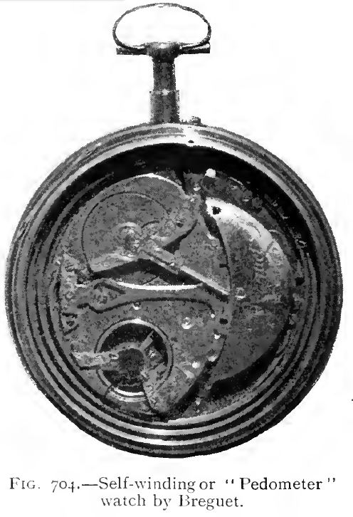 |
| Left: The Recordon Pedometer watch: 1780
The principle of winding a watch by body movement, by means of a pendulum, was patented by Louis Recordon, in 1780, (Patent No. 1249) though it appears the idea was around before that. The term pedometer suggests the watch was meant to be carried in some way so that it was operated by leg movement. The usual way to carry a pocket-watch was in your waistcoat, where it would not have experienced much angular movement.
Modern self-winding (automatic) watches have a rotor rather than a pendulum, and being worn on the wrist experience a good deal of angular movement.
This example was made by the famous watchmaker Abraham-Louis Breguet.
|


