Gallery opened: 17 May 2015 |
Thermal Expansion Engines
|
Gallery opened: 17 May 2015
Updated: 27 Nov 2018
More on Adams thermal expansion engine


Almost all engines work by the expansion of gases, a notable exception being the Malone engine worked by the expansion of fluids. It seems logical to ask if anyone has attempted to make an engine powered by the thermal expansion of solids. The answer of course, humans being what they are, is yes.
| Invar is an alloy of 36% nickel and 64% iron, invented in 1896 by Charles Edouard Guillaume. At this composition the expansion coefficent hits a deep minimum. Guillaume won the Nobel Prize for physics in 1920 for this invention, as it enabled more accurate scientific instruments to be constructed.Zerodur is a lithium aluminosilicate glass-ceramic produced by Schott AG for use in large telescope mirrors. It's about the lowest-expansion material that is anything like commonly available. As you can see from the table, it's considerably better than invar. |
Firstly, we want our expanding material in the form of a long rod as that increases the movement, and will allow the material to be heated and cooled more quickly; from this point of view we want our rod to be as thin as possible while still bearing the forces involved. A rod under tension would be better than one under compression because it cannot buckle.
The speed of heating and cooling is actually a bit of a red herring. We could make a thermal expansion engine that alternately heated and cooled metal rods by steam and cold water, but the slow rate of heat transfer would make the power output tiny, and I don't like to think what the thermal efficiency would be. About the only remotely sensible approach is to accept that the power output is very small and rely on free heating in the shape of solar energy, even though this gives only one cycle of heating and cooling per day; it might be enough to wind a church clock.
Of the common metals that are solid at room temperature, zinc has the largest expansion coefficient at 29.7 x 10^-6. Lead is almost as good, but its low mechanical strength makes it unsuitable. If we take a zinc rod 1 metre long, and heat it from a room temperature of 20 degC to the boiling point of water at 100 degC, which should be quite practicable, then it will increase in length by 80 x 29.7 x 10^-6, or 2.38 mm. That, I imagine will take several hours to develop fully, and clearly gearing that movement up to run a dynamo is going to be quite a challenge. On the other hand there is considerable force behind it, which can be increased easily by increasing the cross-section of the rod, (though at the expense of increasing the thermal capacity and slowing things down even more) and I can easily imagine that with a realistic amount of gearing we could do something like wind up a clock spring.
Now, how to get the power out? If we have light loading most of the expansive force will do nothing. On the other hand, if we constrain the rod completely there is no expansion and no power output- instead the energy has set up a tensile or compressive stress in the rod. By analogy with matched electrical loads, I think we will get the maximum power out when we allow the rod to expand by half of what it would have done when unrestrained; an engineer friend of mine agrees with me. It should therefore be possible to calculate the power output per cycle from the force required to limit the expansion to one half. If the zinc rod is under compression it will almost certainly need intermediate supports to prevent buckling. It will be simpler to keep our rod in tension with a hefty spiral spring, and far fewer if any supports will be needed.
If our expanding zinc is in tension, then it could be in the form of a wire. (I have checked and you can buy zinc wire) While this might make construction simple, it misses the point- the expanding element has to withstand a lot of force, and I suggest the energy available per heating/cooling cycle is proportional to the mass involved; a wire is thin so this will be low. So we will stick with a rod. You can buy zinc rods, though the maximum length available is not yet established.
And so on to the next problem; if our zinc rod is fixed at one end, so we get the full 2.38 mm at the other, well, what is it fixed to? We need a metal chassis which can contain the force of the expansion without significant extension. If we made it out of, er, zinc, then it would thermally expand by the same amount as the rod and the net movement would be zero. Obviously a material which expands less- preferably much less- than zinc is going to be desirable. The table tells us that Zerodur is as good as it gets but it is unlikely to be a practical choice because of cost, if nothing else. Invar is made of nickel and iron, and so should be reasonably cheap. A metre of it under the same 80 degC rise will expand 80 x 1.2 x 10^-6, or 0.096 mm. We therefore have the difference of 2.28 mm to work with, which is 95.8% of the zinc expansion. If instead we used steel, which is presumably the cheapest material on the list, its expansion would be 80 x 10.8 x 10^-6, or 0.864 mm, and we have lost over a third (36%) of the expansive movement; perhaps we should stick with invar. To get the 80 degC differential, I envisage our zinc rod being mounted on the church roof in a linear parabolic reflector; you can buy these off the shelf for solar water heating. The rod will be painted dull black for maximum solar absorption, and perhaps some sort of textured finish will improve the absorption. This sort of thing is no doubt recorded in the annals of solar energy.
So far we have considered a 1-metre rod of zinc (plus 1-meter invar chassis) but given the size of the average church roof I think a 10-metre rod is entirely practicable. (I'm starting to feel like xkcd here; what if we used more power?) That proportionally increases the movement to 22.8 mm, nearly an inch, and we have ten times the power available. I think gearing that up to wind a clock should be relatively straightforward.
At this point I began to wonder about the cost of a 10-meter invar chassis. But the point of our chassis is not that it must have a very low expansion coefficent, but that it should not expand or contract. They are not the same thing. I reckon the cheapest chassis would be a simple steel beam, suitably lagged so that its temperature does not vary significantly over the 24-hour cycle. That should save a bob or two.
But we are not finished yet. We can have multiple zinc rods arranged in parallel, with levers at each end to transmit the movement from one to the other so that they are effectively in series, equivalent to a 100-metre zinc rod, all mounted in the same linear parabolic reflector. That increases the power by ten times again and the movement to 228 mm, so we can really get some work done. We can't afford any backlash in the system so it would be kept under tension by a spring as noted above. Friction is to be minimised by teflon bearings or roller bearings.
With suitable design of the thermal collector the top temperature could no doubt be higher than 100 degC. Best not to carry this too far, for the melting point of zinc is fairly low at 419 degC. I imagine it loses mechanical strength long before it melts; perhaps someone who knows more about zinc than I do can help us here. Another issue may be thermal creep- the zinc rods elongating over time.
I think that's a sort-of-practical design, but I'm sure it could easily be improved. Do feel free to join in.
![]()
FURTHER THOUGHTS
Looking at the table above, mercury has a linear expansion coefficient that at 61 x 10^-6 is more than twice that of zinc. Presumably this refers to mercury confined in an infinitely stiff pipe so only the ends move. Unfortunately mercury is heavy, expensive, and poisonous, so it is not exactly the ideal working material, but this did not deter some people from large-scale experiments with mercury as a working fluid in a boiler and turbine.
Water expands even more, its linear expansion coefficient being 69 x 10^-6. Being very cheap and wholly non-toxic it would be a much better choice than mercury, though it has the awkward property of freezing when exposed to the sort of temperature range found on our church roof. But water expands when it freezes, and perhaps this could also be exploited for harvesting some extra power...
Ethanol has an expansion coefficient of 250 x 10^-6, more than three times greater than water. Even better is gasoline at 317 x 10^-6 but it is a rather inflammable working fluid; ethanol will be safer.
However, we are getting away from the subject of this page which is solid expansion engines. The expansion of water for power generation has been tried, notably by Malone, but without great success. Malone claimed to have generated 50 HP in this way, which I'm sure is more than anyone ever got out of a solid thermal expansion engine.
We will stick with solids. We do not have to confine ourselves to metals, though their strength may be helpful in building the machine. A moment's thought shows that thermal expansion engines are all around us; you may even have one in your kitchen. Cars have thermostatic valves that control the flow of water through the radiator to control cooling. These valves are operated by the expansion of paraffin wax when it liquefies; OK, maybe we're not confining ourselves to solids completely. Using paraffin wax in tension is not going to work, so we will put it under compression in a pipe and make it push a piston as it expands. Hopefully the pipe will not have to be invar; if the wax expands enough we may be able ignore the expansion of a steel pipe. Other existing applications are the wax motors sometimes used to unlock washing-machine doors and operate ventilators.
Comparison with the linear expansion of solids is tricky, but here are some numbers. Paraffin wax is characterised by the number of carbon atoms. C36 has a free volume expansion of 22% when heated from 30 degC to 80 degC.
![]()
JAMES WHITE AND HIS ENGINE: 1822
The earliest suggestion of thermal expansion for power generation that has been found so far is in a book by James White, called A New Century of Inventions, published in 1822. One of the inventions is titled "A mechanical essay in drawing power from expanding metals" and a proposed machine is illustrated in Plate 34. It is however purely a theoretical machine; White proposes using steel rods 20 feet long, heated and cooled by hot and cold air in a way that is not specified. He suggest the engine could be use to pump water, but admits he has no idea of the likely power output. I came across this book at a London book fair; the price was �750, and I am afraid Museum funds do not run to that.
 | Left: White's plan for a solid thermal expansion engine: 1822
|
James White (1762-1825) was a civil engineer and a prolific inventor; one hopes that his other inventions were more practical than this one. He died aged 63 in December 1825, in Manchester.
![]()
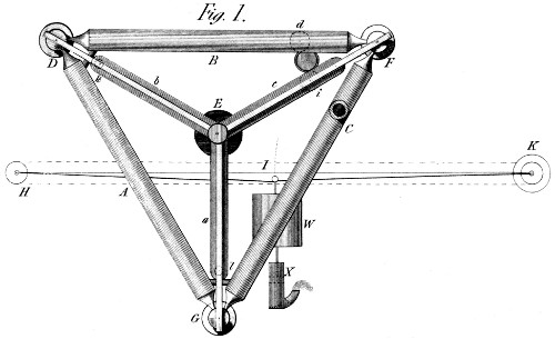
WASHBURN'S THERMAL MOTOR: 1865
George I Washburn of Massachusetts took out a US patent on 4 July, 1865, (No 48,607) for a motor powered by thermal expansion. The expansion of metal rods drove a ratchet which could be used to wind the mainspring of a clockwork motor. The patent gives no details of how the rods might be rapidly heated and cooled to increase the output power.
 | Left: Washburn's attempt at a solid thermal expansion engine: 1865
|
This is presumably the same George I Washburn who took out a US patent for a motor powered by a mixture of air and steam. One is left with the feeling that Mr Washburn did not have much of a grip on the realities of power generation.
![]()
SOLAR THERMAL EXPANSION ENGINE: 1932
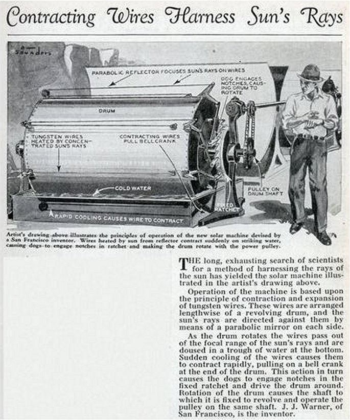 | Left: Solar thermal expansion engine: 1932
|
![]()
THE COMPOUND PENDULUM MACHINE: 1933
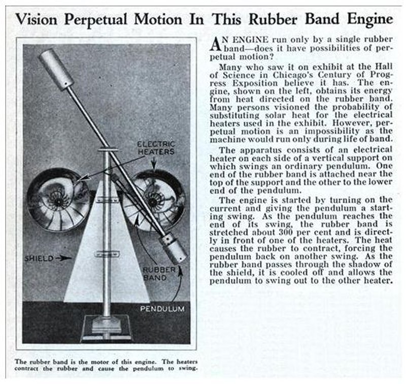 | Left: Exhibit at the Chicago Century of Progress exhibition engine: 1938
|
![]()
THE DUBIOUS MACHINE OF DOCTOR A S CARR: 1938
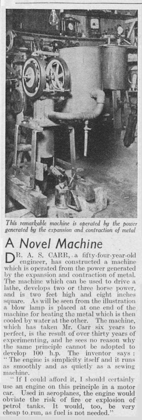 | Left: Alleged solid thermal expansion engine: 1938
|
![]()
ADAM'S THERMAL ENGINE: 1967
 | Left: Adams' thermal expansion engine: 1967
|
 | Left: Adams' thermal expansion engine: 1967
|
![]()
RUBBER-BAND EXPANSION WHEELS: 2013
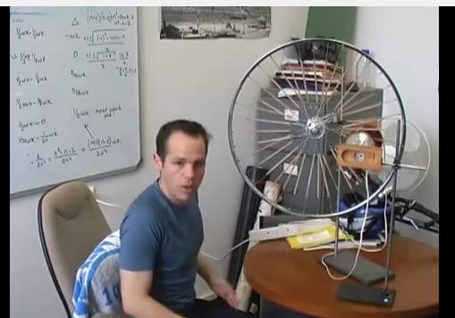 | Left: Bicycle wheel thermal expansion engine: 2013
|
![]()

|