Gallery opened 12 Dec 2017
Updated: 2 Dec 2024
More on Collins & Wagner mother clock added here


The Paris Pneumatic Clock Network |
Gallery opened 12 Dec 2017 |
In 1879 the Austrian engineer Viktor Antoine Popp and his co-worker Resch demonstrated a system of pneumatic clock synchronisation in the Austro-Hungarian section of the Universal Exposition. It appears the actual inventor was Carl Albert Mayrhofer. The Paris city council granted Popp's Compagnie des Horloges Pneumatiques (CGHP) authorization to install a compressed air network to drive both public and private clocks. It was not a power distribution network but a time distribution network, which synchronised a large number public clocks, in particular those of railway stations, by sending a pulse of air every minute. The pipes ran through the sewers of the city, and the tunnels of the Metro and the RER. (The RER is a commuter rail network serving Paris and its suburbs) Each Popp clock contained a metal bellows which advanced a 60-tooth wheel by one tooth per minute. Operation began in 1880; it is interesting to note that this was a long time after the Paris pneumatic post had opened in 1866.
At the time compressed air was in the air, so to speak, following the extensive use of compressed air for rock drilling in the construction of the Mont Cenis tunnel, which was initially expected to take 25 years but was opened in 1871 after only 14 years following the introduction of pneumatic equipment. (Dynamite was also a help in the later years of construction)
Popp obtained French nationality in 1881. He was later involved in the compressed air power network installed in Paris, and then the Branly-Popp radio system.
Before the contract was made between the Paris municipality and his CGHP company, Victor Popp had made some successful demonstrations. By 31 December 1880, 14 public candelabra-clocks and 33 clocks in municipal buildings were in use. In addition, 1475 clocks were in use in various establishments (eg banks, theaters and hotels) of the 11th arrondisemont.
A central transmitting station was set up at 7 rue Sainte-Anne, (in the centre of Paris, intersecting the Avenue de l'Opera)from which issued 10 pipes of 27 mm diameter, from which secondary pipes of 6 mm to 20 mm diameter diverged. The air was at the low pressure of 0.75 bar. The demonstrations were convincing, and after a meeting of the Paris City Council on 19th July 1881, on 12th August the Prefect of the Seine authorised the City to enter into a contract with the CGHP.
The clock system closed in 1927, having become unprofitable.
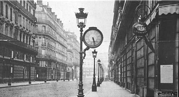 | Left: A Popp clock in a Paris street
This was later enlarged and became the first usine on the Paris compressed-air power network, which was another thing entirely, though also promoted by Viktor Popp. |
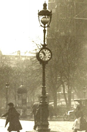 | 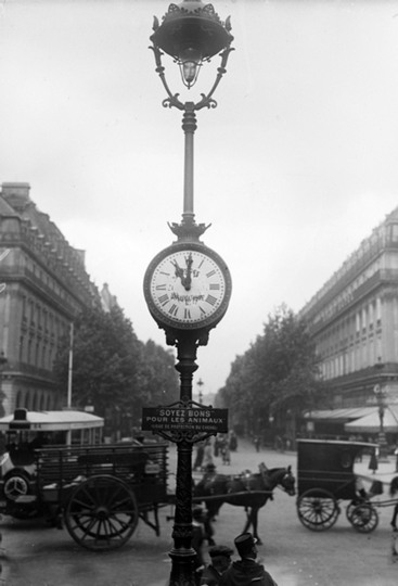 | Left: Two more Popp clocks at unknown locations in Paris
I am however sure about the time- 11 o'clock in the morning. |
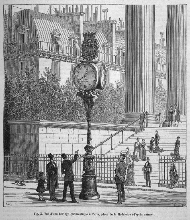 | Left: Multiple-faced Popp clock in the Place de la Madeleine, Paris
|
The following information in quotes is taken from Popular Science Monthly, Vol 20, January 1882 "Time-Keeping in Paris":
"At a central point a steam-engine drives pumps which compress air to five atmospheres (73 psi) in a reservoir holding eight cubic metres. This compressed air is sent, by means of a special regulator, into a second receiver called the "distributing reservoir," where the pressure is kept constant at seventh tenths of an atmosphere, (10.3 psi) or a little less— a pressure determined empirically to be sufficient to move the dials." |
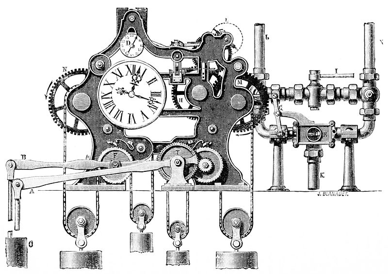 | Left: A Distributing clock
"The "distributing reservoir" is opened to transmit an impulse into the pipes each minute, for about twenty seconds, by a distributing clock. This consists of two distinct clock movements. The one to the left, provided with balance-wheel, counter-weights, etc, is simply an ordinary clock, and indicates the hour, minute, and second, as shown in the figure. The movement to the right is contrived especially for moving the distributing valve, R. This valve, ingeniously arranged in such a way that the pressure acts only on a minimum of its surface, is inclosed in a valve-box and has three orifices."The first of these puts the valve in communication with the "distributing reservoir"; the second puts it in communication with the street-pipes; and the third puts the pipes in communication with the atmosphere. The first orifice is always open; the other two are normally closed. The automatic escape of the lever G, at the end of each minute, moves the slide-valve, opens the second orifice, and sends an impulse into the pipes; at the end of a number of seconds, determined by experience and dependent on the length of the pipes (a number which varies from ten to fifteen seconds), the slide-valve is brought back to its original position by the clock-work, closes the two orifices, and allows the extra pressure which has been introduced to escape into the air. This operation is repeated every minute. "The motive-power for the clock-work of both movements is furnished by the compressed air, which automatically lifts the pistons in the cylinders, C, at the end of each minute. The pistons move the levers B and A; the first of these, B, winds up the counter-weights as much as they have fallen during the preceding minute; the second, A, imparts motion to the slide-valve." |
I find this description defective. The clock movement on the right is just a timer to control the 10 - 15 second pulse of air when it is triggered by the clock on the left. The duration does not have to be determined very accurately, and so instead of an escapement its speed is regulated by the fly or vane labelled L. The lever A does not impart motion to the slide-valve directly, but winds up the weights of the timer by means of the gear teeth on its right extremity. Engineering (24 June 1881) gives the duration of the air pulse as 20 seconds.
Just above the main clock dial is a seconds dial D. The escape wheel is just behind it; (as revealed in the picture of the Vienna distributing clock) despite the reference to a balance-wheel above it looks very much as if it was a pendulum clock.
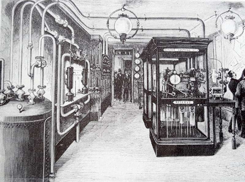 | Left: The Distributing room
|
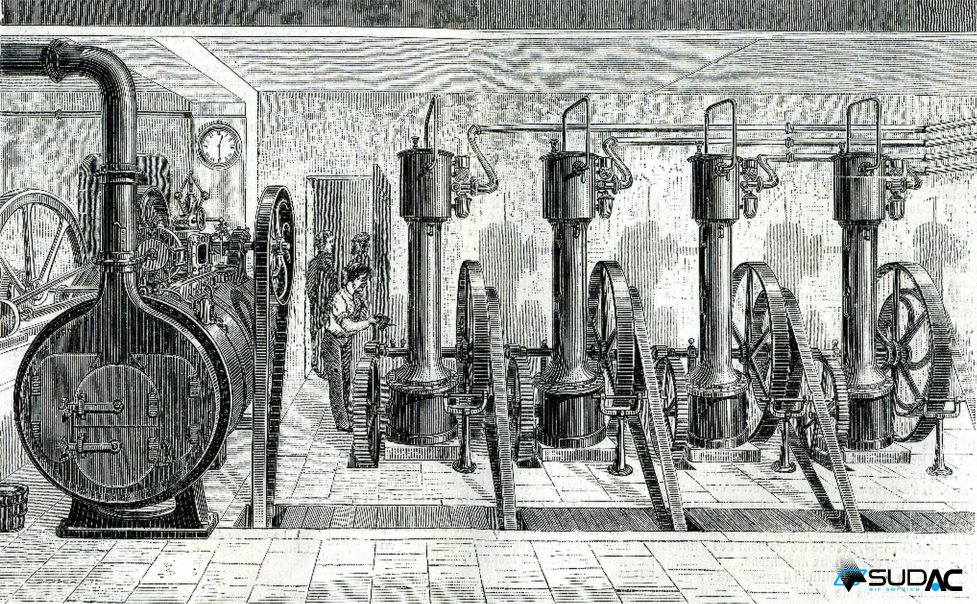 | Left: The compressed-air plant at rue St Anne
|
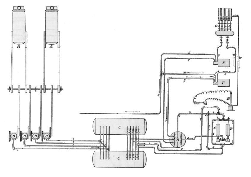 | Left: The compressed-air plant at the rue St-Anne
|
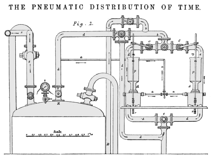 | Left: The compressed-air plant at the rue St-Anne
|
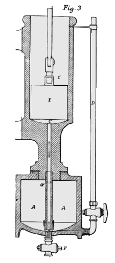 | Left: One of the pressure regulators at the rue St-Anne
|
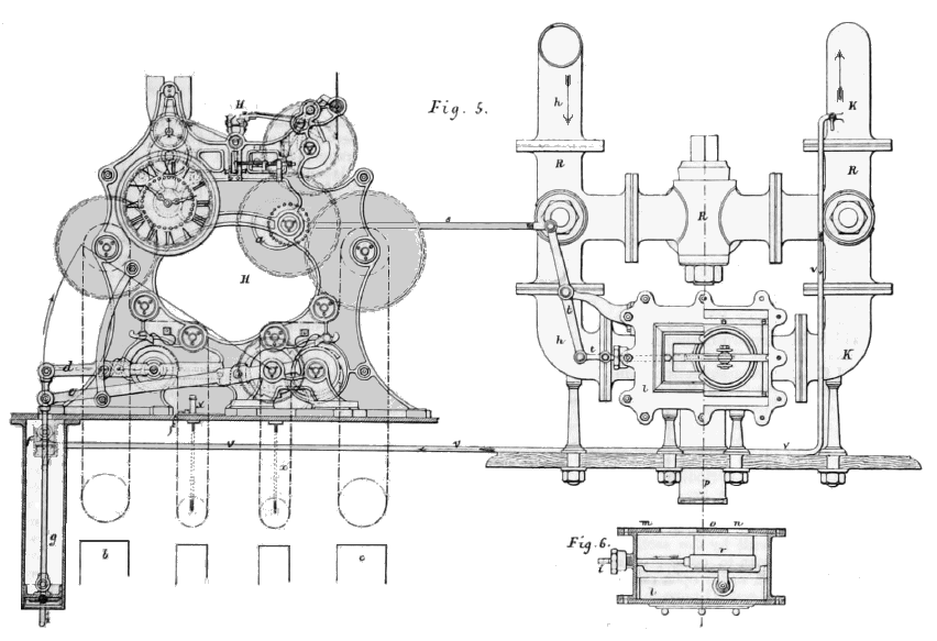 | Left: A distributor clock at the rue St-Anne
|
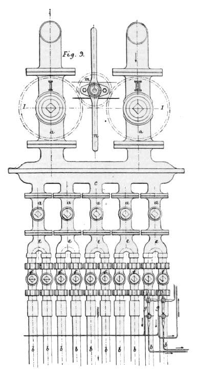 | Left: The distributing valve chest at the rue St-Anne
|
Going back to Popular Science Monthly:
"The impulse given by the clock-work is distributed through the city by means of pipes laid like ordinary gas-pipes. In the streets the pipes are of iron, and have a diameter of twenty-seven millimetres (about one inch); but in the houses the pipes are of lead, and of different sizes—the diameters being fifteen, six, or three millimetres (practically one half, one quarter, or one eighth of an inch), depending on the number and size of the dials to be operated. These pipes are entirely hidden from view, and in no way interfere with the appearance of the dials." |
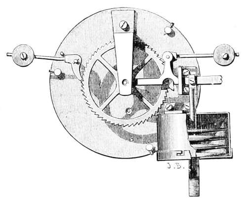 | Left: The mechanism of a Popp pneumatic clock
| ||
"A leather or rubber flap, seen in the cylinder, receives the impulse as it comes from the pipe and moves a piston, which acts upon a lever-arm arranged by simple connections to move the minute-hand one space forward. The ordinary clock-gearing (not shown in the figure) secures the proper motion for the hour-hand. This part of the apparatus can be inclosed in any case—as plain or as ornamental as desired. The cases are made in all the designs and sizes of ordinary clocks, and appear precisely like them, except that the minute-hands jump suddenly over one space at the end of each minute, and remain stationary during the minute, instead of moving gradually over the space." |
Back to Popular Science Monthly again:
"All the machinery of the system is in duplicate, for use when repairs are needed. Delicate manometers indicate the pressure at all times, and the most approved electric apparatus is used to indicate the particular point at which a defect has occurred. A skilled engineer is on the watch at all times. Provision is also made so that, in case of any interruption in the regulator, the dials may be run by hand. Accuracy of time is secured by daily comparison with the observatory clock." |
All very sensible, except that reference to the observatory clock, which must mean it was in the Paris Observatoire (the equivalent of Greenwich Observatory in London) and so some six kilometres away on the other side of the Seine. Investigation was called for...
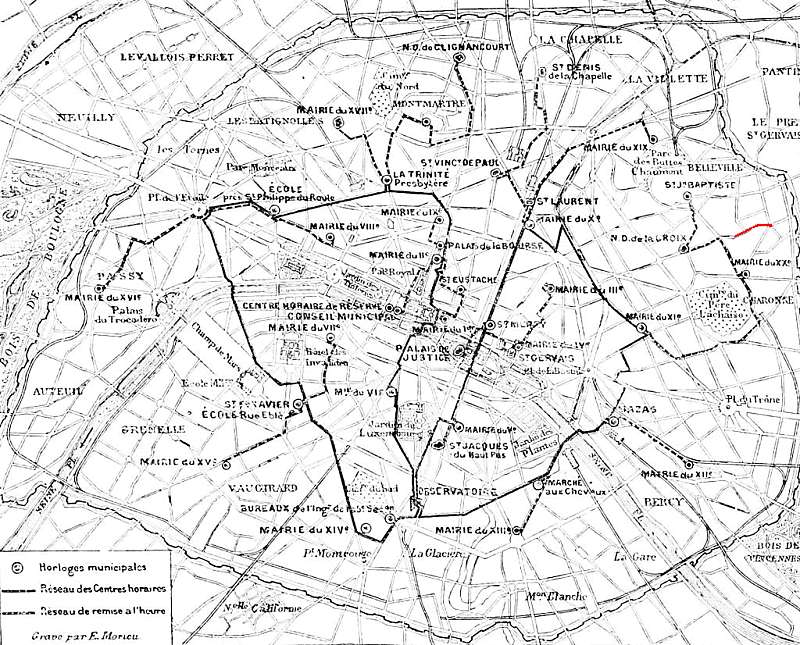 | Left: Electrical time distribution from the Paris Observatoire
|
The secondary regulator at the Hotel de Ville sent synchronising pulses once an hour to the twenty mairies of Paris. (A mairie is roughly equivalent to a borough town hall in London) The nearest mairie to St Fargeau is the mairie of the 20th arrondisment, just to the east of the Pere Lachaise cemetery.
Back to Popular Science Monthly again:
"Excellent as the system is for general uses, the pneumatic dials can not be used for accurate time-work, because it requires in the extreme case, namely, for a distance of twenty thousand metres, at least ten seconds for the impulse to reach its destination. Thus it will be seen that each dial is slow a certain number of seconds, depending upon its distance from the central station; nor has it been found that the error of any particular dial is constant. But the error will never be allowed to exceed ten seconds. Should the extension of the system require it, Paris will be divided into six districts (surveyed so that no point in the city shall be over twenty thousand metres from a central station), each provided with its central station equipped in other respects as the one described, but all receiving their compressed air from a common reservoir centrally located." |
The time delay was something I had wondered about when I first heard of this system. Obviously the ultimate limit to the delay is the speed of sound. Assuming the Paris sewers were at 15 degC, the speed of sound would be 343 m/sec, and a pressure difference could not be transmitted 20 km in less than 58 seconds. Something wrong here, I think.
Back to Popular Science Monthly again:
"However, there are plenty of people in Paris, as there are, doubtless, in every city, for whom a time even ten seconds in error is accurate enough. The system was put into operation there about March 15, 1880, and in the first four months there were fifteen hundred subscribers, distributed in six hundred houses. The popularity of the pneumatic clocks is due to their convenience and cheapness. The rental is only five centimes (one cent) per day for the first clock; four centimes (eight mills) per day for the second clock; three centimes (six mills) per day for the third and every subsequent clock rented by the same person; and the expense of pipes and apparatus is borne by the company." |
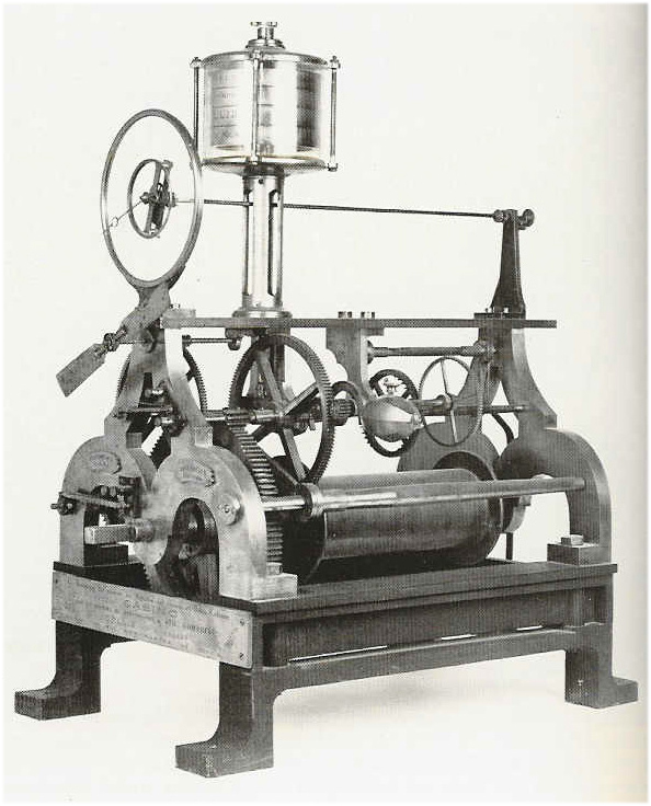 | Left: A Collin & Wagner Horloge mère clock
|
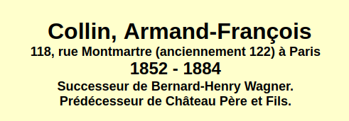 | Left: A Collin & Wagner label
|

  
|