Gallery opened: 25 April 2014
Updated: 28 Apr 2019
More on Tripler added
 
| |
CONTENTS OF THIS PAGE
 When a quantity of liquid air is put into a vessel at room temperature, it very soon starts to boil, at -195 degC, as it absorbs ambient heat. If the vessel is closed then a considerable air pressure can be built up, and this can be expanded in an engine in the same way as steam or compressed air.
Liquid air was first produced in practical quantities by William Hampson and Carl von Linde, who independently filed for patents on the same thermodynamic cycle in 1895. It is usually referred to as the Hampson-Linde process.
CHARLES TRIPLER AND HIS LIQUID AIR ENGINE
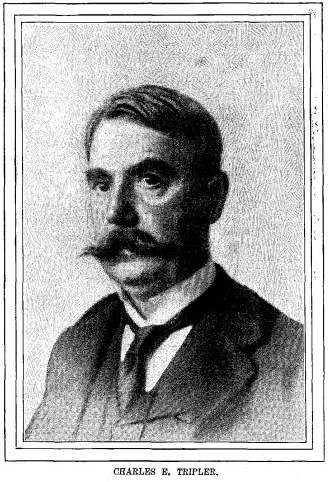 |
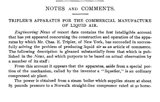
| Left: Charles E Tripler: date unknown
By 1898, Charles Eastman Tripler, (1849-1906) described as "a scientist of New York City", was making liquid air on a large scale. He publicised the remarkable properties of liquid air, (by dramatic demonstrations such as making roses brittle and driving a nail with a hammer made of frozen mercury) and claimed to have greatly cheapened its production. In fact, he claimed to be able to make it at no cost at all, and that is where the liquid air engine comes in.
In the words of the man himself:
"I have actually made about ten gallon of liquid air in my liquefier by the use of about three gallons in my engine. There is therefore a surplusage of seven gallons that has cost me nothing, and which I can use elsewhere as power."
In other words, any given amount of liquid air can triple itself in quantity; equivalent to perpetual motion. Never has a man been more aptly named than Mr Tripler. If this was true, and a practical liquid air engine could be devised, free power would be available in any quantity desired.
These details come from an article in McClure's Magazine by Ray Stannard Baker, March 1899, pp. 397-408.
|
A somewhat different version appeared in The Strand Magazine in April 1899, with copyright acknowledged to the McClure company.
"I saw Mr. Tripler admit a quart or more of the liquid air into a small engine. A few seconds later the piston began to pump vigorously, driving the flywheel as if under a heavy head of steam. The liquid air had not been forced into the engine under pressure, and there was no perceptible heat under the boiler; indeed, the tube which passed for a boiler was soon shaggy with white frost. Yet the little engine stood there in the middle of the room running apparently without motive power, making no noise and giving out no heat or smoke, and producing no ashes."
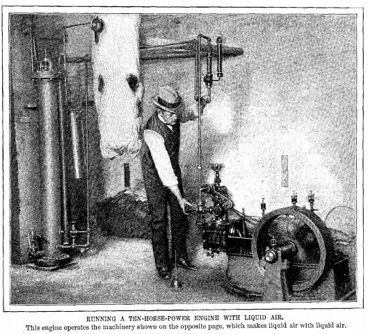 |
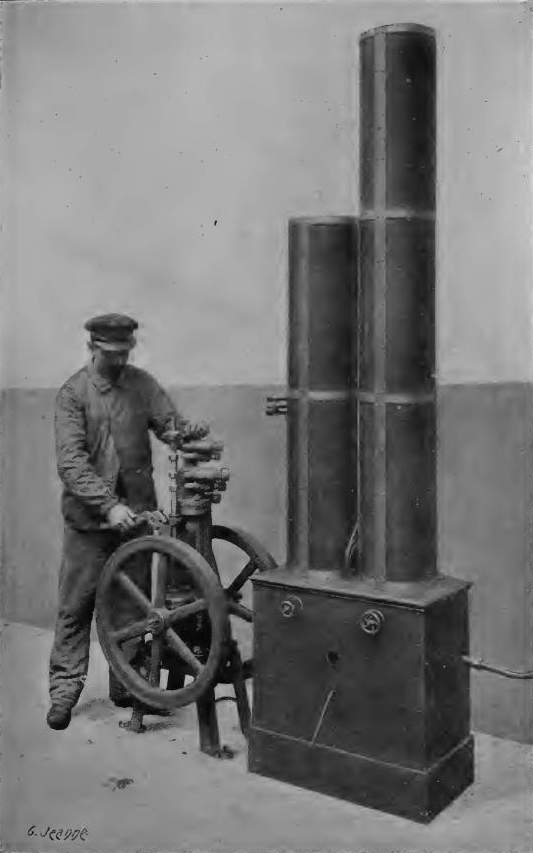
| Left: Tripler liquid air engine running: 1899
The engine seen here appears to be a conventional horizontal steam engine. The blurring of the flywheel spokes shows that it is running. The white cloud in the background is presumably condensation from the cold air exhaust of the engine.
Just to the left of the operator is a strange object which is probably the "tube which passed for a boiler was soon shaggy with white frost." referred to by Ray Stannard Baker above. Mr Baker has (perhaps unwittingly) put his finger on a fundamental snag of cryogenic engines- the obvious way to vapourise the liquid air is in a heat exchanger heated by the ambient air; but that will rapidly become covered with a thick layer of ice from the water in the air. Ice is a poor conductor of heat and evaporation will quickly grind to a halt. It is rather puzzling that the pipe leading to the engine is not also covered with frost.
It is an interesting question as to how this engine was lubricated. Unless the air was heated in some way before it reached the engine, I would have thought that normal lubricating oil would have solidified. There is also the point that the air would get even colder as it expanded in the engine. For all that, the engine has three visible conventional oil lubricators, apparently half-full of oil.
|
From Popular Science Monthly, Volume 55, May 1899, by Ira Remsen:
"There is no doubt that liquid air with its enormous power of expansion can be used as a source of motive power just as compressed air is. In the case of steam it is necessary to heat the water in order to convert it into steam, and to heat the steam to give it the power of expansion. The cost is, in the first instance, that of the fuel. Given a certain amount of heat, and a certain amount of work is obtained. If liquid air is used, the problem is much the same. Engines must be run in order to compress the air which is to be liquefied. Every gallon of liquid air has been produced at the expense of work of some kind, How, the question arises at once. What proportion of the work that was put in that gallon of liquid air in the course of its production can be got out of it again?"
"It is certain that all of it can not be got out unless all that we have ever learned about such matters goes for nothing. In dealing with the problem of the application of liquid air as a source of motive power we are therefore doubly handicapped. In the first place, we do not know the cost of the liquid when produced on the large scale; and, in the second place, we do not know the probable efficiency of a liquid-air motor. I say " we do not know." Perhaps Mr. Tripler and the others engaged'in the experiments on this subject do know approximately. We certainly can not blame them for not telling us all they know at this stage of the work. It is unfortunate, however, that such a statement as was recently published in a popular magazine should be allowed to gain currency � apparently with the sanction of Mr. Tripler. The statement referred to is to the effect that ten gallons of liquid air have been made by the use of three gallons of liquid air in the engine. If that means that the ten gallons of liquid air are made from air at the ordinary pressure, the statement is in direct conflict with well-established principles. [My italics] If it means that the ten gallons of liquid air are made from air that has already been partly compressed, we must know how much work has been done before the liquid-air engine began. Leaving out of consideration the question of cost, it may be pointed out that liquid-air engines would have the advantage of compactness, though they would necessarily be heavy, as they would have to be strong enough to stand the great pressure to which they would be subjected."
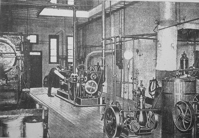 |
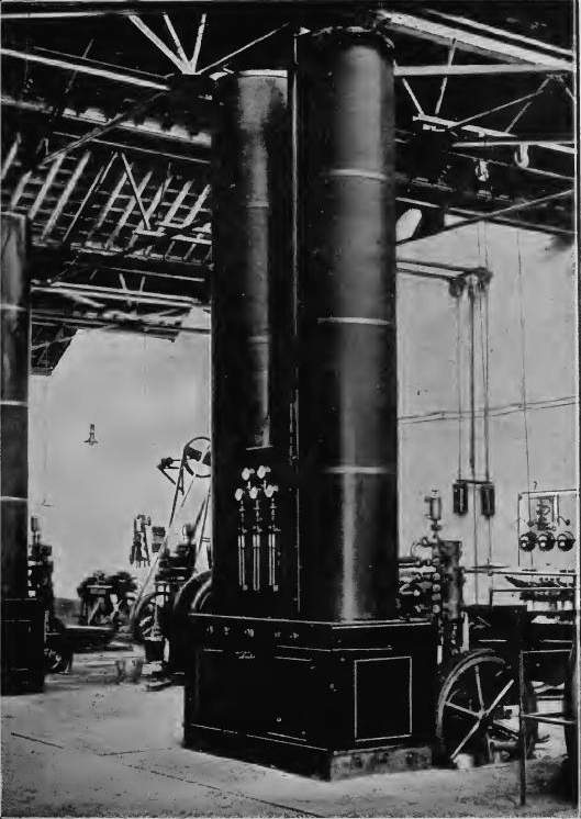
| Left: Tripler's liquid air laboratory: 1899
This shows a steam boiler on the left, and at centre rear the Norwalk three-stage direct-coupled (tandem) compressor; the piston rod ran in a straight line through the four cylinders. The compressor engine was rated at 90 HP at 150 rpm, but for Tripler's work it ran at about 100 rpm. The black cylinder mounted vertically on the wall (picture centre) appears to be the 'duster' which washed the incoming air. The air liquefaction plant is in the right foreground; the white pillar is the lower end of the liquefaction column. Just to the left is what may be a vertical single-cylinder expansion engine.
The following data comes from Sloane's book, mentioned below:
| Diameter | Exit pressure | Relative piston area
| | Steam cylinder | 16 inches |
| | Low pressure air cylinder | 10.5 inches | 55 - 65 psi | 110
| | Intermediate pressure | 6.6 inches | 350 - 400 psi | 44
| | High pressure air cylinder | 2.6 inches | 2,000 - 2,500 psi | 6
|
|
 |
| Left: Diagram of Tripler's liquid air machine: 1900
This diagram corresponds closely with the photograph above, down to the number of hinges on the boiler. Air wass drawn from the roof of the building through a pipe, and through the 'duster' which washed the air clean of dust with a stream of water trickling over baffle-plates. The air was then compressed in the three-stage compressor with two intercoolers, and left the third cylinder at high pressure and hot. It was then cooled, passed through a separator to remove water and oil from the compressor, and then entered the liquefying columns.
So far, standard stuff. However if Tripler's claims were true there must be some wholly new invention in the liquifier columns. T O'Conor Sloane (of whom more later) wrote in his book:
"The construction of the liquefiers has not been fully divulged. The lower end of one is seen in the cut on page 291. ( ) They appear as long felt-covered
cylinders. Inside the felt wrappings are cylindrical cases containing coils of copper pipe. At the bottom of the coil of pipe is a special valve, the invention
of Mr. Tripler. The compressed air escapes from the valve and, expanding suddenly, experiences a drop in temperature. Some of the cooled air
works its way up through the chamber and cools the coils of pipe. Thus there is established an intensive or accumulating action. The air entering the liquefier at a normal temperature is cooled by the reverse flow of expanded air. It escapes from the valve at the bottom at a temperature which constantly grows lower until air begins to liquefy, and collects in the
bottom of the liquefying chamber. Now all is in working order, air is liquefying and collecting, and in a short time liquid air can be drawn off by the gallon just like water."
This certainly sounds like a description of the standard Hampson-Linde process, but gives no clue as to why Tripler's version should apparently be much more efficient. You can't draw off liquid air 'by the gallon' from the Hampson-Linde process.
This image and the quoted text is from Liquid Air And The Liquefaction Of Gases by T O'Conor Sloane.
(pub Norman W. Henley & Co, New York. 2nd edn 1900)
|
It is an interesting book, but not wholly a sound one. Sloane seems to have accepted everything Tripler said at face value.
Despite the air of competence displayed in the book, Sloane was not a specialist in liquefying gases. His other works included How to become a Successful Electrician. However, he was not just an author; he was the editor of Amazing Stories and Scientific American, and also a professor of natural science at Seton Hall University and held a PhD in electrical engineering. He seems to have been a remarkable polymath, if not a reliable critic of thermodynamic scams.
Tripler died of Bright's disease at a hotel in Liberty, New York in 1906. We may spare him some sympathy as it is not a pleasant way to go. Bright's disease also killed Isambard Kingdom Brunel.
The question is, was Tripler a charlatan and a fraud, or an incompetent experimenter who genuinely believed that any amount of liquid air could be made to triple itself? We have to go for fraud. Fairly detailed accounts of Tripler's liquefaction machinery have now been found (see above) but so far nothing on the internals of the liquifier columns. My hypothesis is that his liquifier columns contained in them secret reservoirs in which liquid air previously made was stored; then you really could 'draw off a gallon', and that would fool most witnesses.
 |
| Left: Partial description of the Tripler liquid air process: 1899
This shows that the air compressor needed 90 HP to drive it. This is much greater than the claimed 10 HP output of the liquid air engine pictured above, and that is something that Tripler can hardly have overlooked.
Journal of the Franklin Institute, Volume 146, Issue 2, August 1898, Pages 153�155
I am glad to report that Norwalk are still making straight-line compressors. A straight-line compressor has multiple pistons on the same piston rod, for compact multi-stage compression.
|
Furthermore, from what is known of it, Tripler's machinery was simply a version of the Hampson-Linde process, which by then was well-known. The theoretical energy efficiency of the basic Hampson-Linde process is 7.2%, not 300%.
The Tripler scheme was criticised by Professor Morton of The Stevens Institute, who condemned it as another Keely motor scheme; Keely was unquestionably fraudulent. Mr Tripler laughed this off during his many spectacular demonstrations of liquid air. The Tripler Liquid Air Company was formed, with a share capital of �20,000,000 (under the laws of Arizona, no doubt for a good reason) to exploit the invention. It never put a product on the market before its collapse, and was denounced as a "bubble".
Tripler had taken out a patent on air liquefaction in 1893, and this prevented Linde from registering his own patent in 1895. In 1900 Charles Brush, an independent inventor, bought a Linde air-liquefying machine for his private laboratory. Learning of Linde's patent problems, he supported Linde in litigation against Tripler's patent. It did not go well for Tripler, whose 'transparent lack of knowledge of how his process was supposed to work' and his exaggerated claims about its performance undermined his defense of his patent, and it was ruled invalid. This enabled Linde and Brush to start liquid air production in the USA. Interestingly, Cecil, the son of T B Lightfoot was hired as the managing director of the new company.
I have been unable to trace Tripler's 1893 patent, which seems strange, given its impact on the USA liquid air industry. Are patents removed from the USA system if they are declared invalid?
Here is all I found:
NumberCountry Title Date
US 652,304United StatesLiquid Air Generator June 1900
US 652,058 United StatesLiquifier for Atmospheric airJune 1900
GB189915235A Great Britain Apparatus for Liquefying Atmospheric Air and Utilizing the Same. 1899
ES25932A1Spain An apparatus for settling the atmospheric air 1900
CH19922A Switzerland An apparatus for the liquefaction of air 1899
| | | | | | | | | | | | | | | | | | | | | | | |
|
| The 652,304 patent merely describes a way of unblocking the liquid air machinery.
The 652,058 patent shows the internals of a liquifier, but the purpose of the patent is not air liquefaction as such, but a way of removing impurities like CO2 which would clog up the apparatus.
|
GEORGES CLAUDE AND HIS LIQUID AIR ENGINES: 1902
Georges Claude (1870-1960) was no charlatan- he was a clever and persistent engineer and scientist, though a less than satisfactory character in other directions. (He was an active collaborator with the Germans during the occupation of France during WW2, and in 1945 he was imprisoned and stripped of his honours)
Claude was not interested in liquid-air engines as a source of power, but as a better way to produce liquid air. That sounds paradoxical, but it is not. The Hampson-Linde process, referred to above, was very inefficent compared with the theoretical maximum efficiency. This was because it expanded the pre-cooled air to cool it further, by the Joule-Thomson effect, and liquefy a proportion of it. The Claude process instead expanded the air in an engine, so that work was actually being taken out of the system, and more efficient cooling occurred. The engine was not driven by liquid air as such, but like Tripler's, by high pressure air; nonetheless there was liquid air condensing in the cylinders. After prolonged efforts he suceeded in producing liquid air in 1902.
Claude did not invent the idea of an expansion engine. The use of such a machine to reach low temperatures seems to have been first suggested by Carl Wilhelm Siemens, a German engineer who did most of his work in Britain, in 1857. In that year he patented the Siemens cycle which relies on expansion for coolng. In 1885, Ernest Solvay in Belgium used a reciprocating expansion engine, but could not get below -98 �C because of lubrication problems.
 |
| Georges Claude in 1926
Looking thoroughly pissed-off. He probably looked even less happy in 1945, when he was sentenced to life imprisonment for collaboration; he was actually released in 1950.
He also invented neon signs.
| The use of an expansion engine increased the efficiency, but making it work was a nightmare that took two and a half years. The early versions of the system liquefied the air in the cylinder, and the very low temperatures caused appalling difficulties with lubrication, as almost any lubricant would freeze solid. After much experiment it was found that the engine could be started up with ordinary lubricating oil, (Valvoline) which was gradually replaced with petroleum ether as the temperature in the system dropped. When air began to condense in the cylinder, this liquid gave enough lubrication for operation to continue; a process Claude called auto-lubrication. It does not appear to have been totally satisfactory.
Much of the information here comes from Claude's book Liquid air, oxygen, nitrogen. (1909) In this rather strange work he refers to himself in the third person. It was translated to English in a very rough-and-ready fashion by Henry E. P. Cottrell.
| |
 |
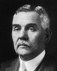
| Left: The expansion engine with which Claude first produced liquid air: 1902
Claude described this as "a simple compressed-air motor" in his book but does not say if was purpose-built or a modified steam engine; probably the latter. He says it had "draw valves" which I assume means a slide valve design. This picture shows a valve-chest (just to the right of the pressure gauge) which looks very much as if it contained a slide valve.
A later development of Claude's process combined the expansion engine with Hampson-Linde throttling; liquefaction occurred at the throttle and not in the cylinder, which therefore ran at higher temperatures where the lubrication problems were less severe.
Like many of the photographs in Claude's book, this has a rather peculiar smeared look; reason unknown.
|
 |
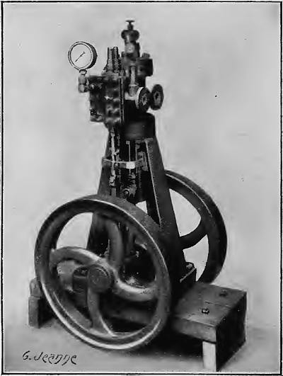
| Left: A later expansion engine for the Claude process
Claude says that this engine used "trap valves" instead of "draw valves" because of problems with the latter. This term is also a bit obscure (as I said, the English version of his book is written in a very idiosyncractic way) but I think it means poppet valves. The picture here appears to show poppet valves, driven by push-rods, on either side of the central cylinder.
This design was worked out by Claude's assistant, Le Rouge. Much trial and error was required to get satisfactory results. One disconcerting problem was the brittle fracture of the cylinder at low temperatures. As Claude put it "they... break like glass under a blow which is only slightly violent."
|
 |
| Left: Two liquefaction towers, with the expansion engine to the right
After 6 years of experimenting Claude developed a satisfactory expansion engine. Early versions were lubricated with petroleum ether, but degreased leather washers as piston rings proved effective.
|
 |
| Left: A smaller liquid air plant, with the expansion engine to the left
However, one wonders why there are no pipes visible connecting the engine to the columns. Possibly a posed shot of non-working equipment, but we get an excellent idea of the size of the engine.
|
Claude later used compound liquefiers, in which the expansion was carried out in two stages, the expansion engine have high and low pressure cylinders connected in tandem.
The company formed by Claude, Air Liquide is still very much in existence.
HANS KNUDSEN AND HIS LIQUID AIR CAR
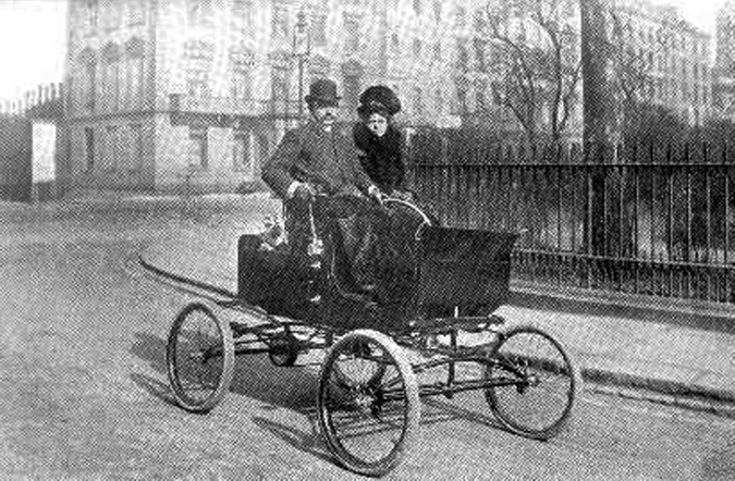 |
| Left: Liquid air car: 1903
In 1899 Hans Knudsen designed a car called, with a certain lack of originality, Liquid Air. This did not prosper; the company behind it went into receivership in 1901, but Knudsen still demonstrated the car at a London motor show in 1902. This photograph was taken in 1903.
Where Knudsen got his liquid air from is currently unknown. Presumably the company had its own machine.
|
 |
| Left: The internals of the Liquid Air car: 1903
The liquid air was stored in the double-walled tank A, which also seems to be surrounded by some sort of granular insulation. There seem to be filling valves on top of the tank.
The long spiral tubing B was presumably where the liquid air was turned to gaseous air by the ambient heat of the atmosphere. It looks as though it would have quickly clogged with external ice.
The engine C is a vertical type, driving the rear wheels through a chain; nothing else about it is known at present.
The pedal J looks as if it may be connected to a brake on the rear axle.
|
THE JAPANESE LIQUID AIR ENGINE
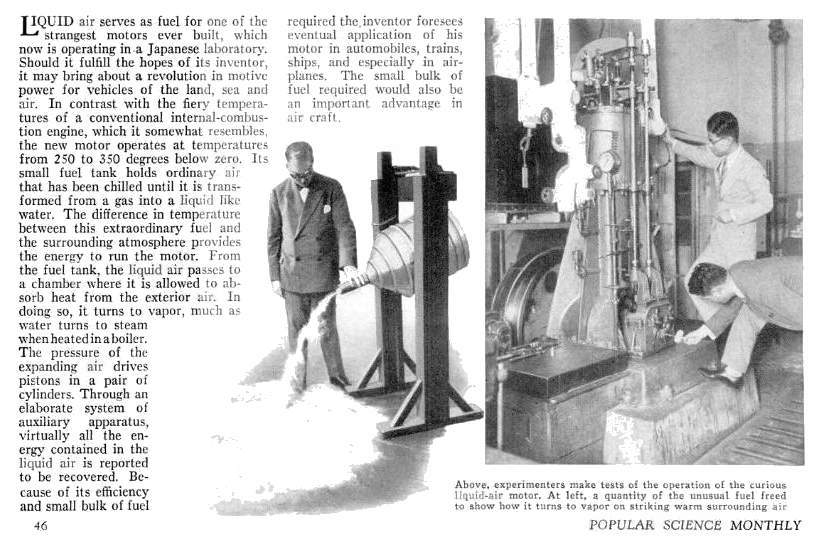 |
| Left: Japanese liquid air engine: 1935
That looks to me like a single-cylinder vertical engine, earther than a two-cylinder one. The white pipes are a puzzle- they appear to be insulated, but since the liquid air has to be heated by ambient air to vapourise it, why would you need to insulate it afterwards? I imagine that the "absorb heat from the exterior air" bit is going to be much more difficult than this glib phrase suggests. I imagine everything covered in a thick layer of poorly-conducting frost.
From Popular Science Feb 1935. The same article appeared in Popular Science Monthly on the same date.
|
Note that the text misleadingly describes liquid air as a fuel, which implies that the author had very little understanding of the subject.
It seems highly unlikely that this could be a viable engine, given the difficulty of transporting and storing liquid air. Vapourising it with the ambient air is also likely to present serious problems, as noted above. Compressed-air engines are cooled as the air expands and are very susceptible to freezing up; I imagine the problems here would be much compounded by the liquid air starting off at a very low temperature while compressed air was stored at ambient temperature. Porter came up with an ingenious system to deal with this that might have been of use to the Japanese.
Not for the first time in compiling these galleries, I have been struck by the suspicion that some sort of scientific spoof is going on, like the Grand Pajandrum, or the persistence of acoustic location devices in newspaper articles when radar was already a reality. Japan was very much at war at the time; they were fighting China, having invaded Manchuria in 1931, and thereby demonstrated the impotence of the League of Nations. (Pearl Harbour was not until December 1941) Possibly this liquid air scheme was a deliberate attempt to deceive foreign governments.
