A dicycle or diwheel is not to be confused with a bicycle. It has two big wheels side-by-side with some sort of frame between them, and is inherently unstable in the front-back direction. Compared with monowheels, there have not been many. There is a Wikipedia page on diwheels.
THE OTTO DICYCLE
 |
| Left: The Otto Dicycle: 1870s.
Designed by a Mr Otto and manufactured in the 1870s by the BSA company of Britain.
Note the little wheel on a stalk at the rear to stop you falling over backwards. Presumably falling forwards was your own responsibility.
|
THE HOLSON DIWHEEL
 |
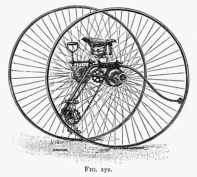
| Left: The Holson electric diwheel, with motors in each wheel hub: 1899
This diwheel was built by Mr A B Holson of Chicago. It was electrically driven, with a large set of batteries slung underneath and providing good anti-gerbil ballast. Holson said: "The reason that batteries give out so quickly in automobiles is that the vehicle shakes the batteries so badly that the active material drops out, and there is a tendency to short-circuit the battery. I overcome this by having such a large wheel." Probably true enough up to a point, but no suspension is visible and so the batteries would still suffer jolts.
The machine was not put into production. Here it is apparently being tested in the snow.
Source: The English Motor-Car Journal, 1899 Issue.
Information on the diwheel is scarce, but it has emerged the diwheel was described in Western Electrician 23 Feb 1901, under the title of "The Holson Two-wheeled Electric Vehicle", where the method of driving the wheels independently by means of electric motors mounted in the wheel hubs, with a system of transmission gearing, was described. |
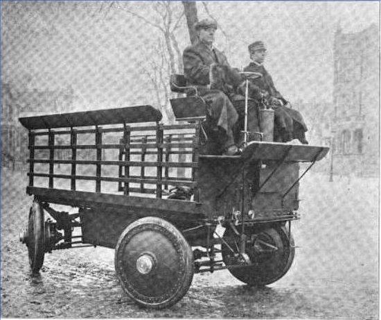 |
| Left: The Holson electric truck with motors in the wheels: 1904
However, more about Mr A B Holson emerged. In 1904 he built a battery-powered four-wheel truck with four electric motors mounted in the wheels. An article describing it in Western Electrician in 1904 said "Mr Holman appears to have laid aside his idea of a two-wheeled vehicle."
The motors in the truck wheels are fully described in the 1904 article. The motor shaft was horizontal and at each end it had a small pinion, each driving a separate toothed ring attached to the wheel. The arrangements in the diwheel were very probably similar. What Mr Holson may not have appreciated is that all the motors were unsprung weight which would have a bad effect on handling.
As can be seen in the photograph, the truck had four-wheel steering.
The 1904 article states that the truck was built by The Holson Motor Patent Company of Grand Rapids, Michigan. It was exhibited at the Chicago Auto Mobile Show in 1904.
Source: Western Electrician 2 Jan to 25 June, 1904.
|
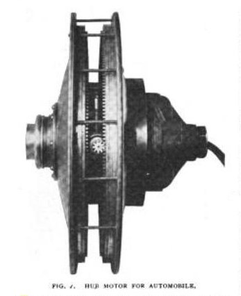 |
| Left: One of the wheels from the truck: 1907
The electric motor is sandwiched between the two toothed plates. Compare with the rear wheel in the photograph above.
There does not seem to be a route for air flow to cool the motor.
|
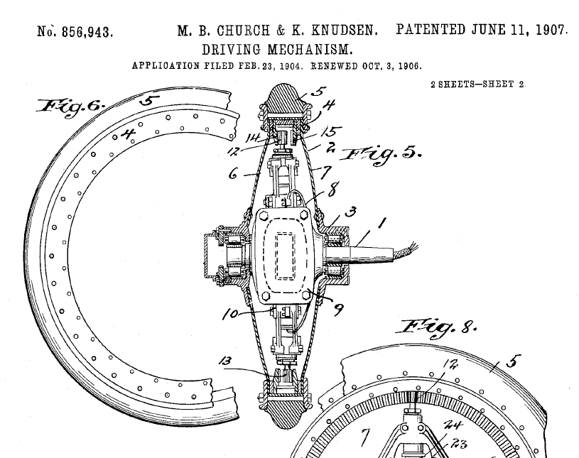 |
| Left: Patent drawing showing how the motors drove the wheels: 1907
The motor 9 is fixed to the fixed axle 1 and does not rotate bodily. Each end of the motor shaft carries a small pinion 12, 13, each driving separate toothed rings 14, 15 attached to the wheel, so the sense of rotation is the same.
Note that the motor has to be mounted at a slight angle so the pinions engage different toothed rings.
M B Church was chairman of The Holson Motor Patent Company (Holson was the vice chairman) while Karsten Knudsen actually built the truck.
Source: US Patent 856943A of June 1907.
US 792599A of July 1904 is a very similar patent.
|
 A MULTIPLE DIWHEEL FOR THE BLIND: 19??
 |
| A Multiple Diwheel For The Blind: 19??.
This remarkable bit of engineering was 'Found on the Web' and details are currently lacking. It was built, almost certainly by Singer & Co, in 1882 for the Royal National College for the Blind in Upper Norwood, London. Here it carries 11 blind riders and one steersman. (probably the man in the flat cap)
There are six pairs of wheels.
Date of picture currently unknown
|
 |
| A Multiple Diwheel For The Blind: 19??.
This looks like a trip around the College gardens.
Regrettably very little can be seen of the construction of the multiple diwheel.
There seems to be a misprint. It was The Royal National College, not the Royal Normal College. Crass.
|
 |
| A Multiple Diwheel For The Blind: 19??.
This picture gives a little more information on the mechanical arrangements. Each diwheel section carried two people. The front rider had pedals and a chain running back to the central axle, while the rear rider had pedals and a chain running forward to the central axle. There is no sign of any brakes.
According to the accompanying caption to this photograph, one man in front was sighted and the other seven riders were blind. This implies that there were two multi-diwheels, or that an 8-person machine was extended to 12 riders. Unfortunately the rear of the machine here is out of view.
The multicycle was built in 1882 for the Royal National College for the Blind.
|
A MULTIPLE DIWHEEL FOR THE MILITARY: 1887
 |
| A Multiple Diwheel For The Military: 1887.
Looking at the multiple diwheel just above, I recalled having seen a group of soldiers on a very similar machine. And here it is, on trials at Aldershot, England in 1887. No other image has so far been found.
As far as I can make out, the mechanical construction is the same as the Diwheel for the Blind just above. It was definitely made by Singer & Co.
There are here seven pairs of wheels, as there is a trailer at the rear for carrying ammunition, rations, etc.
The original illustration had a caption above the inset picture at top right, saying 'making a zereba of the machine'. The word is normally spelt zariba and refers to a thorny hedge thrown up as an obstacle. An ingenious use of the multiple diwheel.
It is odd that the soldiers have their rifles slung with the butt upwards; can any expert on military etiquette explain if this is unusual?
Source: Scientific American (June 11th and July 16th, 1887)
|
 |
| A Multiple Diwheel For The Military: 1887.
This is the only other image found so far. Note trailer attached at the rear.
|
Looking at the multiple diwheel just above, I recalled having seen a group of soldiers on a very similar machine. And here it is, on trials at Alders
This is from �Discovering Old Bicycles� by T.E. Crowley.
�They (Singer & Co.) were also responsible for the Multi-military cycle which carried eight, sixteen or more between pairs of wheels coupled together with towbars, and wound its sinuous way along like some monster road-serpent. But not for long. Mechanical millipedes carried whole clubs that year, but like the last and clumsiest of the dinosaurs, they proceeded on their way to oblivion�
|
THE GLEN BRYANT DIWHEEL
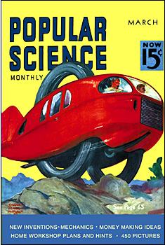 | | 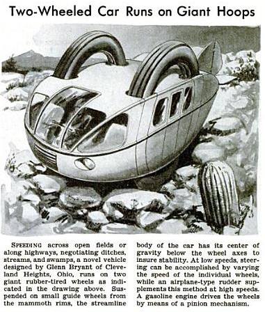 |
| Artist's impressions of the Bryant diwheel on the cover and inside Popular Science: 1938.
The text is rather evasive as to whether this machine was ever built, but since we are looking at drawings rather than photographs I assume not...
I wonder how well rudder at the back would have worked at high speed. Changing a wheel in the event of puncture looks as though it might have been interesting, and where do you put the spare wheel?
From the March 1938 edition of Popular Science.
|
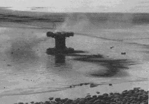
THE GRAND PANJANDRUM
An unassailable contender for the title of the most dangerous diwheel of all time is the British Grand Panjandrum. This World War 2 weapons system was designed by Barnes Wallis, the inventor of the Dambusters' bouncing bomb, and was intended for attacking beaches. The Panjandrum consisted of two 10-foot wooden wheels with 1-foot wide steel treads, joined by a central drum, and propelled by small powder rockets attached to the rims. The central drum was intended to be fitted with a massive explosive payload- no less than 4000 pounds.
The intention was to carry the Panjandrum close inshore in a landing craft, drop the front ramp, and ignite the rockets. The great wheel would then plunge through the shallows and roll up the beach at 60mph, crushing barbed wire until it encountered a suitable enemy obstacle, when it would explode. How detonation would be triggered at the right time is currently unknown.
In reality the rockets fired unevenly, the direction of travel was completely unpredictable, and it was much a danger to its own side as to the enemy. At least one demonstration saw the onlookers fleeing for their lives before the Panjandrum toppled over on its side and stopped careering about.
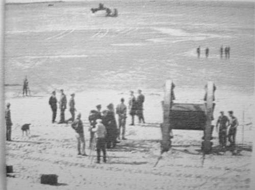
One test was described in detail by Brian Johnson, for the BBC documentary Secret War:
"At first all went well. Panjandrum rolled into the sea and began to head for the shore, the Brass Hats watching through binoculars from the top of a pebble ridge [...] Then a clamp gave: first one, then two more rockets broke free: Panjandrum began to lurch ominously. It hit a line of small craters in the sand and began to turn to starboard, careering towards Klemantaski, who, viewing events through a telescopic lens, misjudged the distance and continued filming. Hearing the approaching roar he looked up from his viewfinder to see Panjandrum, shedding live rockets in all directions, heading straight for him. As he ran for his life, he glimpsed the assembled admirals and generals diving for cover behind the pebble ridge into barbed-wire entanglements. Panjandrum was now heading back to the sea but crashed on to the sand where it disintegrated in violent explosions, rockets tearing across the beach at great speed."
The prototype was built in great secrecy at Leytonstone, in East London, not a mile from where I sit and type. It was transported with similiar secrecy to Devon, travelling at night, but once there all security evaporated.
Testing was done on the beach at Westward Ho, a seaside resort in Devon. This "secret weapon" was tested several times in full view of holidaymakers, leading to some interesting speculation as to its real purpose- see below.
 | | The Panjandrum just before a test: 1943/4
The dark wedge-shapes visible on the two wheels are the solid-fuel rockets.
|
A film of this thing in operation exists on Youtube; the Panjandrum sequence starts at 1 min 58 sec in. Note that the commentator suggests that the whole thing was conceived to deceive the Germans as to the Allied landing site. A model of the Panjandrum was built for the 65th anniversary of the Normandy Landings, and set off on the original beach in Devon; it was 6 feet high and 3 feet wide and loaded with fireworks fitted by Skyburst of Bristol, instead of explosives; it was expected to travel 500 metres at a speed of up to 24 km/h. It travelled in a straight line, but only for 50 metres before running out of thrust.
 | | The Panjandrum: 1943/4
The panjandrum comes to rest on its side on the beach after a less than successful test run.
|
The final trial was in early January 1944, and was ludicrously unsuccessful. The idea was dropped.
It has been suggested several times that in view of the very public trials the Panjandrum was actually a masterly piece of misdirection, and part of FORTITUDE SOUTH, the ambitious and highly successful operation to convince the Germans that the D-day invasion would be in the Pas de Calais. This was the most formidable part of the "Atlantic Wall" where the Great Panjandrum might conceivably have been useful; the actual landings were made on the less heavily fortified Normandy beaches. The astonishing lack of security at the Westward Ho tests makes this a tempting hypothesis- after all, the technology so disclosed would not exactly useful be useful to the Germans. It has been said that there were more than 15 filmed public 'trials' of various forms of the Panjandrum. That is no way to maintain any sort of secrecy.
I find this convincing. However, there appears to have never been an official statement on the matter.
THE VEREYCKEN/FRAQUELLI DIWHEEL: 1947
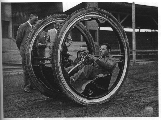 | | The Vereycken Diwheel: 1947
Driving this diwheel is clearly no laughing matter.
|
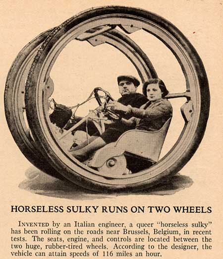 |
| The Vereycken Diwheel: 1947
Aha! This is clearly the same diwheel as that shown above.
For some time this machine has been unidentified. Now, thanks to research done by Stephen Ransom, it can be revealed that it was patented in Belgium in 1947 by Edouard Vereycken, who gave an address in Brussels. The patent number is 473,555 and is titled �V�hicule � deux roues solidaires l�une de l�autre�. The patent was filed on 29 May 1947.
116 mph? I think not!
The "Italian engineer" attribution also seems to be wrong. Edouard Vereycken sounds very much like a Belgian name to me. But see below...
|
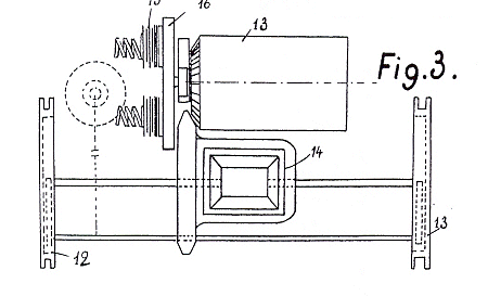 |
| The Drivetrain of the Vereycken Diwheel: 1947
Taken from the patent drawings. Unfortunately what is going on here is far from clear, and certainly not patently obvious. There is clearly a differential between the two wheels, but the rest is obscure.
Diagram courtesy of Stephen Ransom.
|
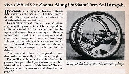 |
| Or was it invented by an Italian after all?
This article comes from June 1935 issue of Modern Mechanix and it states clearly that the inventor was one Ernest Fraquelli. The photograph is the same one as that above, but without the removal of the background. The text states that it was demonstrated in Brussels, Belgium, but the date is rather out of line for a Belgian patent in 1947; what was Edouard Vereycken up to? The situation is currently unclear.
116 mph crops up again. Oh come now...
This article was kindly brought to my attention by Brian Paul Wiegand.
|
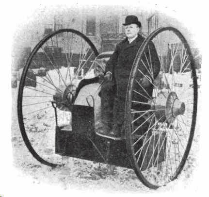
EZEKIEL'S WHEEL: 1980s
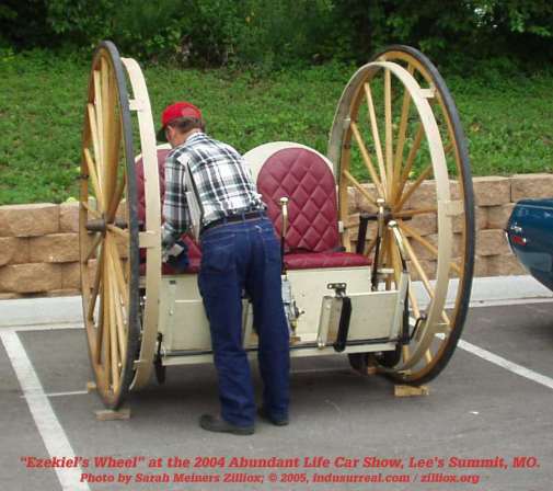 |
| This is called "Ezekiel's Wheel,"
It was built somewhere in the Missouri Ozarks, probably in the 1980s. It has a small industrial motor for power. The two brass levers in front of the seat on the right control the power split to each wheel, for steering.
The current owner is Warren Hunting of Lone Jack, Missouri, who I have tried to contact without success. I hope he doesn't mind me using the picture.
The reference is to visions of wheels in the first chapter of Ezekiel, Old Testament.
Image courtesy of Peter Zilliox.
|
A GERMAN DIWHEEL: 1986
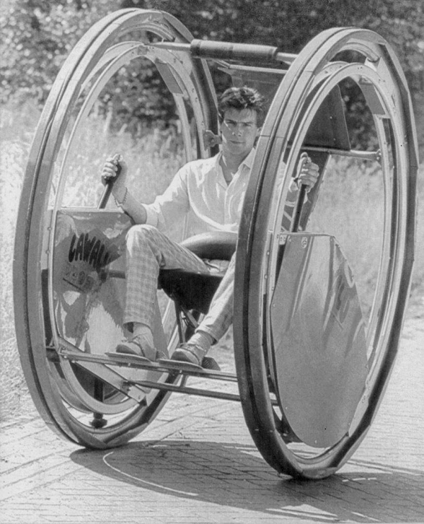 |
| Left: The 'Luvalu' diwheel: 1986
According to The British Monowheel Association, "On 3 July 1986: The 'Lawalu' cruises through the streets of Germany."
Nothing else currently known. Do those pods on each side contain electric motors?
|
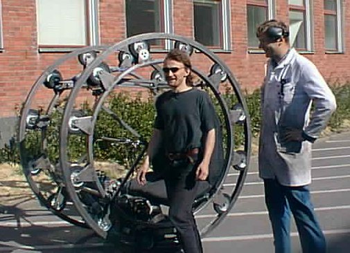
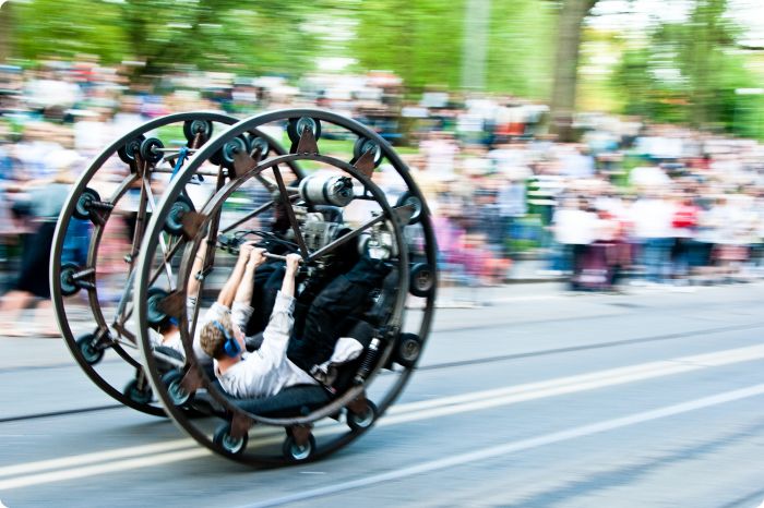
A SWEDISH DIWHEEL: 1999
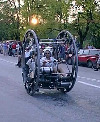 |
| Left: This diwheel was built by some Swedish students at Gothenburg, and has taken part in Summer parades since 1999.
Further info from Jonas Bj�rkholtz (the designer)
Engine: 2-cyl 2-stroke snowscooter engine of 400cc
Diameter: 1.96m
Width: 1.3m
A brilliant movie clip of this machine (including some gerbilling) can be found at:
http://www.mtek.chalmers.se/~johjes/doc/hjulet.mpeg
|
 |
| Note the large number of idler wheels around the circumference compared with other designs on this page.
The designer's explanation regarding the large number of idler wheels: "think 'ball-bearing'. In Gothenburg we have an quite well known manufacturer, SKF."
|
 |
|
Gerbilling merrily at a summer parade.
|
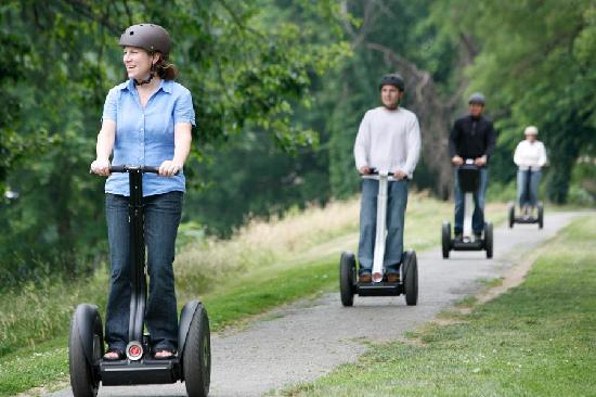
THE SEGWAY: 2001
Probably the best-known diwheel is the Segway. Here is the Segway website
 |
|
Segways are commonly used for guided tours.
|
GBO AMPHIBIOUS DIWHEEL: 2005
 |
| This amphibious concept machine has been produced by GBO Design in Holland.
This concept was developed by GBO for the Brabantse Spelen, a Dutch design competition, in 2005. It was put forward as an amphibious bike for the city of Helmond in the Netherlands, a city allegedly with as many water channels as roads. This statement I find puzzling as looking at Helmond with Google Maps seems to indicate that if anything Helmond has rather fewer canals than most Dutch towns.
Note the pronounced inward camber of the wheels, a feature shown by no other diwheel on this page.
See more here:
GBO Design. The pictures on the GBO website show another float under the centre of the diwheel. I wonder about the stability of this thing on water; diligent searching has so far failed to come up with a picture of it floating, and that might be significant...
Thanks to Ben Burch for bringing this to my attention.
|
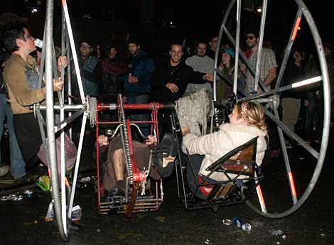
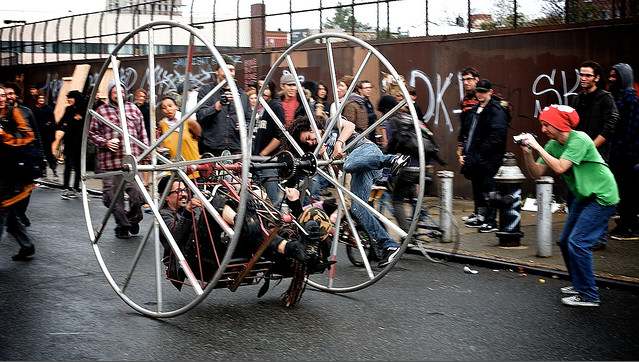
THE BIKE KILL DIWHEEL: 2008
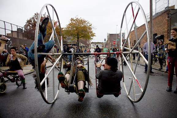 |
| Large two-person diwheel at Bike Kill 2008
To go forward one rider has to pedal forwards and the other backwards- if they pedal in the same direction the diwheel spins on the spot. Note passenger clinging to the left wheel.
The strangely-named Bike Kill is a festival of eccentric cycles held annually in Brooklyn, New York.
|
It was built by The Madagascar Institute, based in Brooklyn, which defines itself as an "art combine" specializing in "large-scale sculptures and rides."
 |
| Large two-person diwheel at Bike Kill 2008
Note that the pedals have to be geared down rather than up because of the large size of the wheels.
|
 |
| Large two-person diwheel at Bike Kill 2008
|
THE STEAM ROLLER: 2009
 |
| Do-It-Yourself diwheel with dual pedal drive
Plans to build this machine have recently been posted on www.instructables.com. There is a impressive video of the diwheel in action.
|
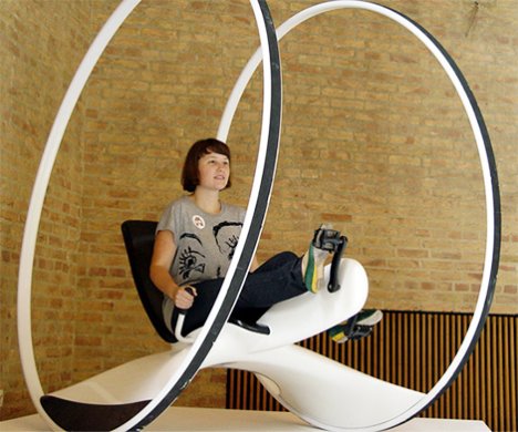
THE TRINITY DIWHEEL: 2009?
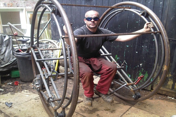 |
| Trinity diwheel under construction
This diwheel was inspired by this very web page. It used to be called The RedMax. Electric drive is intended.
See: redmaxmonowheel.co.uk
|
THE EDWARD DIWHEEL: 2011
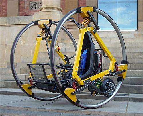 |
| Edward (Electric Diwheel With Active Rotation Damping)
This advanced and truly impressive diwheel was built as a mechanical engineering project at Adelaide University in Australia. A team has been working on it for the past three years. It is powered by two electric motors and has a number of sensors, including a gyro and accelerometer, which are used to measure and control the behaviour of the diwheel using a microprocessor. Acceleration, deceleration and steering are controlled by a joystick. The outer wheels are rolled and welded stainless steel tube with a rubber strip bonded on the outer rolling surface.
"Slosh control" has been implemented in EDWARD to reduce the intrinsic rocking motion during rapid acceleration and deceleration. This term usually refers to the behaviour of liquid in tanks, see Slosh dynamics, so I suppose its main purpose here is to stop the driver from throwing up.
|
This link to Edward gives a lot of detail, including a 215-page technical report, and includes a video with an impressive demonstration of gerbiling. A 5-point racing harness keeps the driver in his seat.
A magnificent achievement!


