Gallery opened June 2005
Updated: 12 Dec 2025
Unidentified Air Locomotives added here.


Compressed-Air Locomotives |
The principle of compressed-air propulsion seems very simple. Pressurise your storage tank, connect it to something very like a reciprocating steam engine, and off you go. At least you are spared the difficulties, both technical and medical, of using ammonia, petrol, or carbon disulphide as the working fluid.
Unfortunately there are still problems. If you have ever pumped up a bicycle tyre, you will know that the pump body gets uncomfortably hot quite quickly. Compressing a gas generates a lot of heat, and all this energy is lost when you store the air and it cools down. The losses can be reduced by compressing the air in two or more stages, and cooling it between the stages, but they are still substantial.
At the other end of the process, using compressed air to run an engine, the main problem is keeping the system working at all. When a gas expands it gets colder, and unless the stored air is perfectly dry (which it won't be) ice will start forming in the pipework and engine, and things will soon grind to a halt.
Compressed-air systems flourished, insofar as they did, in situations where the smoke, sparks and steam of the much more effective steam engine were not acceptable- in city streets, and down coal mines- and at a time before electricity was a viable means of propulsion. There were several compressed-air tram systems, though none proved very successful, and most were quickly abandoned. Compressed-air locomotives in mines lasted longer, but they too were eventually replaced by electric haulage. Now read on...
GENERAL INFORMATION
A long article on compressed air locomotives and their use appeared in Compressed Air Magazine for Oct 1902, Vol 7 No 8, p2000 - p2006.
FIRST STEPS: 1800-1828
About 1819, William Murdock and David Gordon are believed to have made some experiments with compressed-air carriages, apparently for road rather than rail, but nothing is known about the results. By 1821 David Gordon had attempted to set up a company to promote road locomotives propelled by a high pressure engine, or a gas vacuum engine, or a pneumatic engine supplied by what he called "portable gas". He was the father of Alexander Gordon, who specialised in lighthouses.
William Mann, of Brixton, turned his attention to the subject in 1827, obtained a patent in 1828), and published a pamphlet on the subject in 1830. He advocated compression in stages, now recognised as essential for the efficent production of air at high pressures, and the erection of power stations along the high roads at intervals of 15 to 20 miles, or a continuous iron main with power stations in the coal districts.
In 1828 Bompas took out a patent for a compressed-air locomotive in England. There were two storage tanks between the frames, with conventional cylinders and cranks. It is not clear if it was actually built. (Knight, 1880)
Projects for compressed-air vehicles go back a long way. In 1799 George Medhurst patented a scheme for "A condensing wind engine capable of being applied to all kinds of purposes in which steam, water, wind, or horses are employed." Here condensed means compressed rather than liquefied. In 1800, he received Patent 2431 for a scheme for "a new improved method of driving carriages of all kinds by means of an improved Aeolian engine." Medhurst contemplated a general system of coaches and stage-wagons throughout England, with a network of air-compressing stations, most apparently being powered by windmills. He described compressors and engines of variable power, a rotary engine to be fixed directly upon the hind axles of light vehicles, and a gunpowder engine, this last in connection with an artillery wagon. This is the only reference to a compressed-air rotary engine discovered so far. Medhurst endeavoured to form a company with a capital of Ł50,000 to work this project, but the scheme appears to have come to nothing. (much of this information comes from Motor Cars and the Application of Mechanical Power to Road Vehicles, 1902)
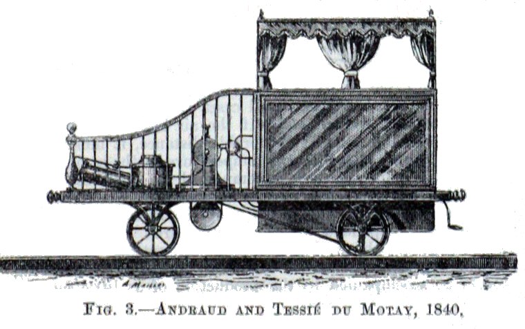 | Left: The first Andraud and du Motay compressed-air locomotive: 1840
|
A description of trials of this first locomotive appeared in the Mechanic & Chemist, p207. We learn that "...air can be compressed almost without expense, wherever there is a stream or windmill to work the machinery..." which is a little optimistic.
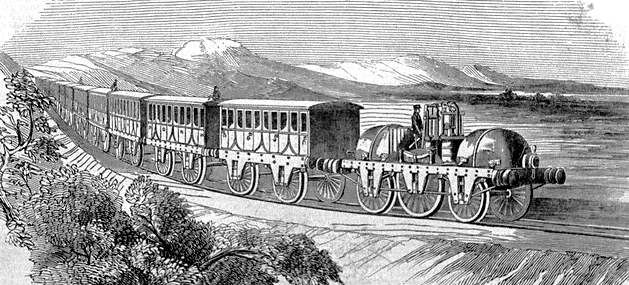
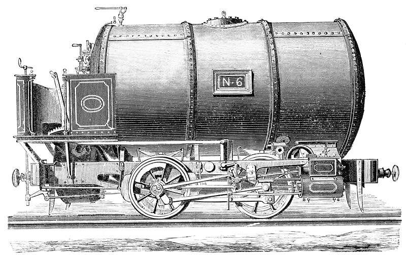
In 1844 M. Andraud built a 2-2-2 locomotive weighing five tons, with a single rivetted air tank holding 106 cubic feet of air at 300 psi. It was first tested on Saturday 21st September 1844 on the Versailles Left Bank track where it covered a two mile return journey at a speed of between 17 and 20 mph. A 1841 patent reveals that Andraud and Tessie du Motay were based at No 35, Rue Chabrol, in Paris; this road still exists and lies to the south-west of the Gare du Nord, where channel tunnel trains from Great Britain terminate.
The image below is believed to be of this machine. It looks a good deal more practical than the 1840 prototype.
 | Left: Andraud compressed-air locomotive: 1844
|
<--
THE AIR LOCO OF LEVI BISSEL: 1841
 |  | Left: compressed-air locomotive: 1841
|
THE 'LIQUID-AIR LOCOMOTIVE' OF WILLIAM EVANS: 1845
In the Geelong Advertiser and Squatters' Advocate (no, I'm not making that title up) for Saturday 28 Mar 1846, it was reported that a certain William Evans, of Philadelphia, had invented a locomotive driven by liquid air. The Geelong was skeptical, and rightly so; the continuous production of liquid air was not achieved until 1895, simultaneously by Hampson and Linde. Evans claimed that the air was liquified 'By means of enormous compression' but nitrogen and oxygen are what used to be called permanent gases, the name coming from the belief that they could never be liquified. They can be liquified but only by combining compression with cooling down to very low temperatures. Evans makes no mention of this.
Evans' claims were clearly fraudulent. I think considerable credit should be given to the Geelong Advertiser and Squatters' Advocate for being fully cognoscent of the thermodynamic impossibilities in the claim.
Exactly the same account of Evans' doings appeared in Littell's Living Age, p113 Volume 7 1845, which states that the original article was published in the Memorial du Rouen. The article appears in other places, such as Mechanics Magazine.
Apart from that no other trace has been found of William Evans and his chicanery.
 | Left: The Parsey compressed-air locomotive: 1847
|
The USA patent contains a rather worrying second section in which the basic air locomotive is provided with means for pumping air back into the receiver after its use in the engine. Parsey says "I propose under some circumstances instead of allowing it to blow off like the steam of a high pressure engine, to return the compressed air into the receiver A after it has acted upon the piston." I assume he means reservoir A (ie the main storage tank) as the receiver is labelled D, which means that the used air would have to be raised to 1000 psi or so; this confusion about terms undermines one's faith in Mr Parsey. And what does "some circumstances" mean?
Now if this pumping-up referred to regenerative braking it would be impressive; but it does not, and it raises the fear that some sort of perpetual motion is intended. In fact Parsey suggests the pumping might be done by hand (which sounds totally impractical) but he prefers to "employ a small steam engine" for the task. Therefore our beautifully simple air locomotive now has added to it a steam boiler, water tanks, storage for coal, and so on. It is a daft notion, and suggests that Mr Parsey was not a very practical man.
 | Left: Contemporary illustration of the Parsey compressed-air locomotive
|
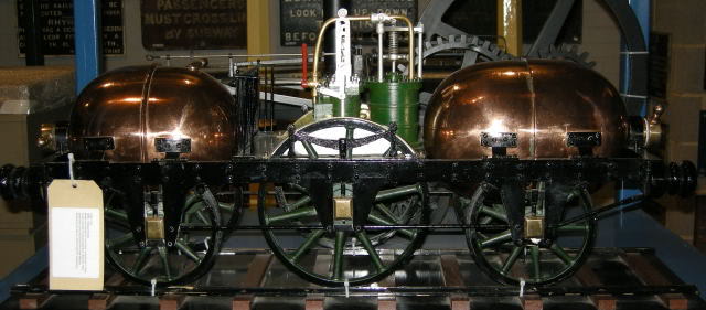 | Left: Model of the Parsey compressed-air locomotive
|
In 1846 the Parsey model was on display in at the office of Parsey's Compressed Air Engine Company, No 5 Pall Mall East, where it was viewed by one William Williams of Regent Square, London. He was not impressed. He felt that "...the high praise and patronage that have been bestowed upon the invention" was undeserved, as it overlooked the power loss at the reducing valve. He accepted that the reducing valve took in a small amount of air at high pressure and yielded a larger volume at a lower pressure, but had convinced himself there were mysterious losses that would reduce the range of the locomotive to one or two miles.
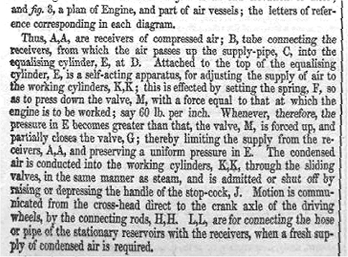
Williams' thoughts were published in Mechanics Magazine, Volume 44, p200, Sat 14 March 1846, No 1179. Another critic was 'A W', whoever he was, who regarded the Parsey proposal as a 'bubble' ie highly speculative and possibly dishonest. He seems to have even less grip on the situation than Mr Williams, believing that the pressure drop at the reducing valve represented power that was entirely thrown away. He concludes, "I cannot help adding farther that 1000 psi is a dangerous pressure to be so employed. The projectors assert that air possesses all the expansive power of steam; this is quite true, but it is also true that it is equally dangerous."
That seems a fair comment if Parsey was intending to use copper vessels at 1000 psi.
There was some more equally uninformed bitching on p221 of that issue of Mechanics Magazine, from 'J M', whoever he was, about reducer losses. None of the correspondents mentioned the source of the very real inefficiency of the overall process- the losses when the air was compressed in the first place.
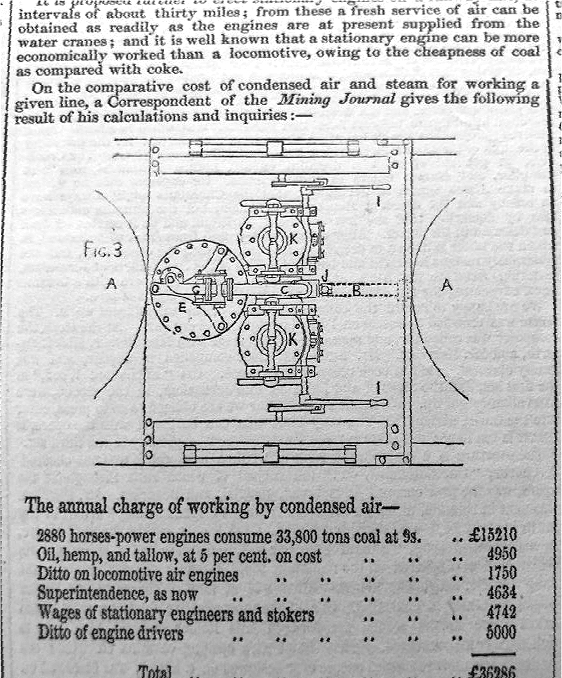 | Left: The engine of the Parsey compressed-air locomotive: 1846
|
 | Left: The engine of the Parsey compressed-air locomotive: 1846
|
What exactly Parsey was up to from 1846 to 1852 is currently unknown, but in the latter year a somewhat more practical Parsey locomotive with a single storage-vessel was trialed.
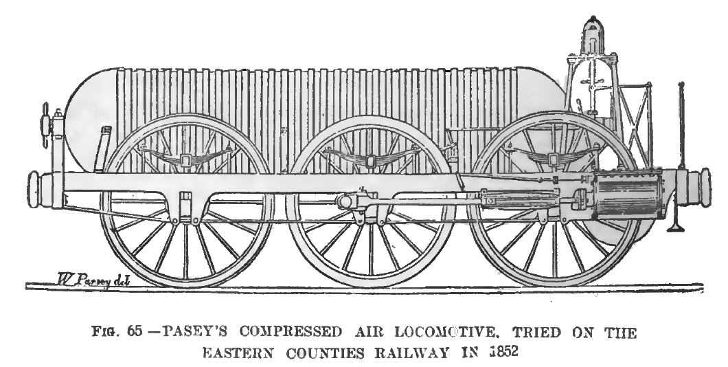 | Left: The Parsey single-vessel compressed-air locomotive: 1852
|
From the The evolution of the steam locomotive, 1803 to 1898;
"The engine in question was constructed by Arthur Pasey, and was tried on the Eastern Counties Railway in July, 1852. This machine was, in point of size and power, nothing more than a model, the dimensions being : Cylinders, 2.5 in. diameter, 9in. stroke ; driving wheels, 4ft diameter; weight, 1.5 tons; air capacity of reservoirs, 39 cubic ft."By reference to the illustration (Fig. 65) it will be seen that this curious little locomotive had the six wheels of 4 ft diameter within the frames, and the horizontal cylinders outside the frames, and actuating the centre pair of wheels- Above the frames was placed a cylindrical air reservoir, with egg shaped ends. This extended from the buffer beam at one end of the vehicle to the leading axle, a distance of about 12 ft. The remainder of the space, about 4ft, was occupied by the pressure-reducing and other apparatus, and afforded a place of vantage for those in charge of the machine. The reservoir was constructed to withstand a pressure circa 200 lb, but the engine was only pressed to 165 lb., and this at the time of the trial at Stratford was reduced to 20 lb working pressure. With a load of eight people, the engine ran the four miles, Stratford to Lea Bridge and back, in 30 minutes. The incident of the trial so aroused the curiosity of the men engaged at the Stratford Works, that they all left their employment for the purpose of witnessing the trial of so great an innovation as Pasey's compressed air locomotive. For this reason no further trials could be held at Stratford, but on July 2nd a second trip was made at Cambridge, and on this occasion, with six passengers, the following results were recorded : Starting from the 60th mile-post near the Waterbeach Junction, with a working pressure of 15 lb. per sq. in., the first mile was covered in five minutes. By increasing the pressure on the pistons, the second mile was covered in four minutes; the pressure was then reduced to 18.85 lb., and 3.5 additional miles were covered in ten minutes. The designer of this little machine gives eight reasons by which he apparently succeeds- at all events to his own satisfaction- in proving the great superiority of compressed air traction over that of steam. Unfortunately for Mr. Pasey's theory, steam is still triumphant, and compressed air dead- or nearly so- for tractive purposes." |
Mr Sekon was clearly not impressed with the design or the concept, but he does not say why. Probably he thought the range between fillings with air would be inadequate. A pity he couldn't get Parsey's name right.
Google has little to say about Arthur Parsey, but this appears to be the same man. If so he lived from 1791 to 1857. His major interest seems to have been poetry, at which he was apparently not very successful. His "single volume of poems was coldly received".
Still assuming we have the right man, in 1832 he published The quadrature of the circle discovered. Since the quadrature of the circle, as usually described in Euclidean geometry, is quite impossible, this may give some insight into Parsey's attitude to perpetual motion.
BARON VON RATHLEN: 1848
In 1848 Anthony Bemhard, Baron von Rathlen, constructed a vehicle which was run from Putney to Wandsworth on several occasions in that year. The carriage weighed three tons, and on its first run, with the reservoirs only partly charged with air, it covered a mile at the uniform rate of eight miles an hour. On another occasion it carried about twenty passengers from Putney to Wandsworth at a speed of over twelve miles an hour. The reservoirs were in the form of tubes, and were of 75 cubic feet capacity ; the air was stored in them at a pressure of from 50 to 60 atmospheres. The working pressure in the engine cylinders was five atmospheres, and a reducing valve was employed to bring down the storage pressure to the working pressure. Von Rathlen's system comprised special methods of cooling the air during compression and of supplying heat to it when working. The ultimate fate of this carriage is not known, but the inventor was still engaged in inventing compressed-air engines twenty years later.
JULIENNE'S VEHICLE: 1855
At the end of 1855, a constructor called Julienne ran some sort of vehicle at Saint-Denis in France, driven by air at 25 atmospheres. (350 psi) It weighed about a ton when loaded.
THE GILBERT COMPRESSED-AIR SCHEME: 1872
I have found a reference to Rufus Gilbert's Elevated Company, chartered in 1872, which was to run along 6th Avenue to 59th Street in New York on compressed air power. It was apparently "stalled by the financial panic of 1873".
THE ST GOTTHARD TUNNEL COMPRESSED-AIR LOCOMOTIVES: 1875
The Saint Gotthard rail tunnel in Switzerland was built in the period from 1871 to 1881. It is 9 miles long and is the highest section of the Gotthard Railway in Switzerland, connecting Göschenen with Airolo. It was the first tunnel through the Gotthard mountain massif. It is double-track and standard gauge. Difficulties were encountered removing the spoil from the long tunnel headings; steam locomotives could not be used because of the very limited ventilation. The high price of horses and the large number required prevented their use. Therefore a first experiment was made with compressed air, in which two ordinary steam locomotives were employed, one at each side of the tunnel; the boilers being filled with condensed air at 4 atmospheres rather than water. The results were encouraging, and purpose built compressed air locomotives were constructed by Schneider et Cie (Schneider-Creusot) of France.
 | Left: Compressed air locomotive used at St Gotthard : 1876
|
The operating pressure is stated as 7.35 kg/cm2 (105 psi) which is low compared with later machines, and similar to the boiler pressures of the steam locomotives of the day; this was probably no accident, for if you are experimenting with machines that might explode you want to start with existing technology. It is noticeable that the air tank has a greater diameter, apparently thinner plates, and fewer and smaller rivets than later high-pressure machines.
 | Left: The St Gotthard system: 1875
|
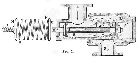 | Left: The Ribourt reduction valve
|
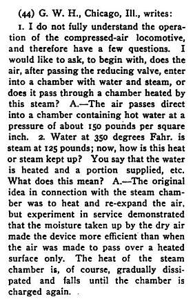
The air from the main tank comes in at A. When the pressure at the outlet D acting on the piston N exceeds the force set by screwing down the spring, the valve M noves to the left, closing the ports and reducing air flow. From D the air passed to a small reservoir that absorbed fluctuations as the cylinders took air. Presumably there was also some sort of throttle valve between the small reservoir and the cylinders; this is so far unconfirmed, but there is something that looks very like a regulator handle sticking out of the rear of the tank in the first picture above.
The Popular Science Monthly implies that this reducing valve was a major advance, but it seems to have been anticipated by Andraud and du Motay, Baron von Rathlen, and Arthur Parsey, if not others. (see above)
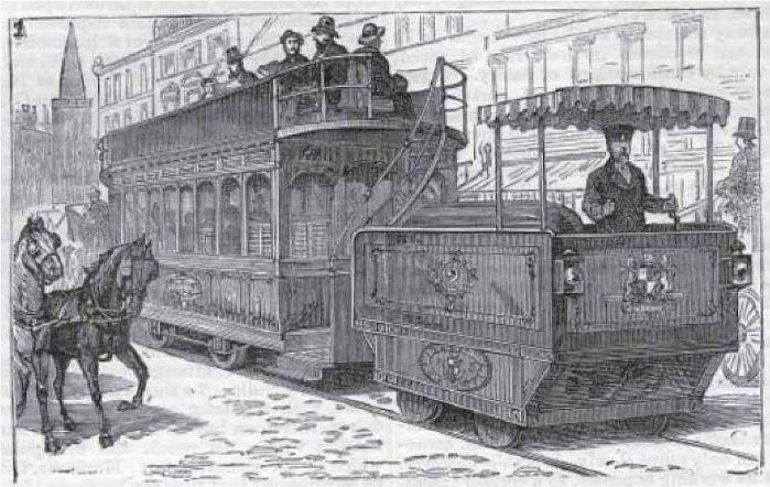
THE HARDIE COMPRESSED-AIR LOCOMOTIVE: 1878
In 1878 the Second Avenue Railroad of New York City tested and then operated for a period in 1879, five tramcars built by the Pneumatic Tramway Engine Company. They were designed by Robert Hardie, who had General Herman Haupt, a civil engineer, as an enthusiastic backer. Haupt wrote extensively and plugged compressed-air trams at every opportunity. The tram engine had one stage of expansion, and is said to have had a more advanced type of preheating than the Mekarski tram system, though it still seems to have used hot water; the details of this are currently obscure. The storage pressure appears to have been 1000 psi, but the engine working pressure is currently unknown. Regenerative braking was introduced; using the engine as a compressor to slow the tram, hot air could be forced back into the storage tanks, increasing the range, enhancing overall efficiency, and alleviating if not eliminating the problem of running out of air for braking. The Hardie trams were supplied with air at 1000 psi by the 1500hp steam-powered four-stage compressor used by the Manhattan Elevated Railway; this also powered the Hoadley-Knight pneumatic locomotives mentioned below. Note the use of multi-stage compression to reduce losses.
An article in the French journal La Nature states that compressed-air locomotives on the Hardie system were giving satisfactory results on the Elevated Railways of New York, though there are few details of the working and it is not clear from the text whether the locomotives were on trial or in regular operation. If anyone can provide more details I would be most grateful.
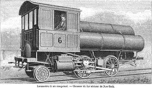 | Left: Illustration from La Nature of a New York air loco: 1882.
|
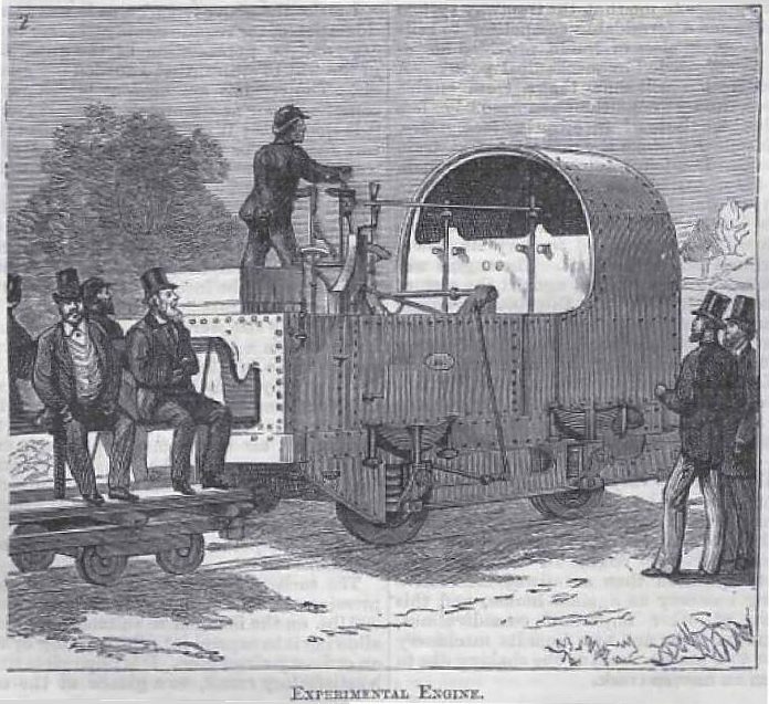
COLONEL BEAUMONT AND THE ROYAL ARSENAL AIR LOCOMOTIVES: 1881
Lieutenant-Colonel Frederick Beaumont was appointed to run the railway network of the Royal Arsenal in 1873. By 1876 he was taking interest in compressed-air locomotives as a safe way of operating a site where large amounts of explosives were stored. By 1877 an experimental 18-inch gauge locomotive was working; it was a very small machine with sixteen main air reservoirs and four as a get-you-home reserve.
The Royal Arsenal at the time was manufacturing the Whitehead torpedo under licence. These were powered by compressed air, and the Arsenal had compressor equipment capable of charging reservoirs to 1000psi.
In a paper in the Society of Arts Journal for 18 March 1881 Beaumont said "The earliest attempts were confined to compressing air at a comparatively low pressure, say 200 pounds per square inch" This pressure was low by later standards, but still twice that used in the Saint Gotthard tunnel. Beaumont said it gave a limited power output, but there were still problems with freezing of the engine cylinders.
 | Left: Beaumont air loco patent: 1880
|
On the 25 of July 1979, an order was placed with Manning Wardle for a standard-gauge compressed-air locomotive with storage at 1000psi. This had its first public test on 6 May 1880 when it ran successfully on the track of the SER between Dartford and Woolwich Arsenal. Details of this locomotive are sparse, but according to the Dartford Chronicle the engine had six cylinders which were fed from an 'expansion box' which presumably reduced the 1000psi storage pressure to an engine pressure of the order of 200psi. How these cylinders were arranged, and if there was a geared drive to the axles, is unknown. We do know however that the piston stroke was 12 inches, and there were six coupled wheels of three feet in diameter. It was known as Manning Wardle No 761.
 | Left: Beaumont air loco patent: 1880
|
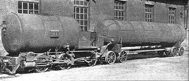
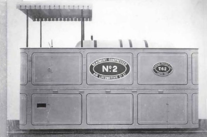 | Left: Works photo of Manning Wardle locomotive No 762: 1880
|
 | Left: Manning Wardle locomotive No 762: 1880
|
 | Left: The Greenwood & Batley locomotive: 1880
|
COLONEL BEAUMONT AND AND HIS CHANNEL TUNNEL AIR LOCOMOTIVES: 1883
Lieutenant-Colonel Frederick Beaumont was also involved in compressed air locomotives for the Channel Tunnel. A tunnel was first proposed in 1802 by Albert Mathieu-Favier, a French mining engineer. When it became clear that the ground under the channel was solid chalk, and practically ideal for easy tunneling, as opposed to blasting through rock, several schemes wre put forward, often involving giant chimneys mid-channel to ventilate the tunnel. The present tunnel is 377 feet below water level at its lowest point, and that would require a pretty serious chimney, which would be a navigational hazard in the busy Channel.
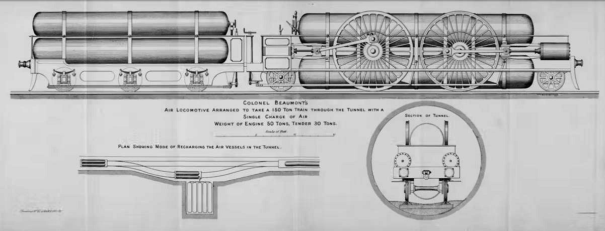 | |
Above: Beaumont air loco for the channel tunnel: 1883
|
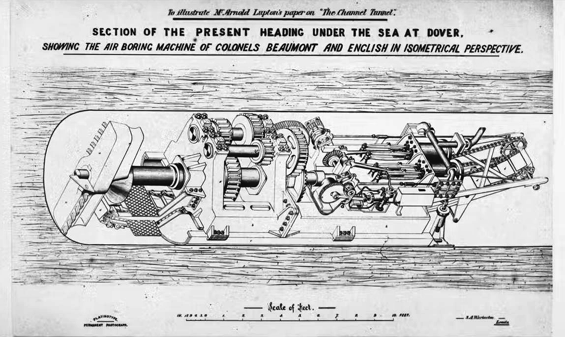 | |
Above: compressed-air boring machine for the channel tunnel: 1883
|
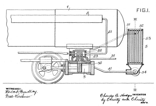 | Left: Hodge patent for reheat by ambient air: 1907
|
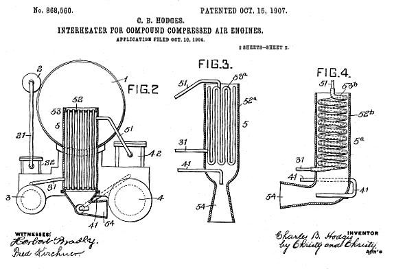 | Left: Hodge patent for reheat by ambient air: 1907
2: Auxiliary reservoir 3: High-pressure cylinder 4: Low pressure cylinder 5: Interheater 54: Ejector |
CHARLES HODGES AND THE PORTER COMPOUND AIR LOCOMOTIVES: 1908
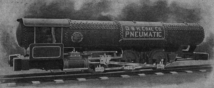
The H K Porter Company of Pittsburgh bought the rights to Hodge's US patents and sold hundreds of locomotives so equipped to coal-mines in the eastern USA, in the period 1896-1930. In 1910 Porter had 90% of the market. They were used extensively in gassy mines where explosions were an ever-present danger. No doubt the cold exhaust air was once more welcome to supplement the mine ventilation.
A typical Porter engine stored air at between 800 and 1200 psi, throttled down to 100 to 150 psi at the cylinders. The air was compressed in multi-stage machines, and distributed by pipe to charging stations along the haulage routes. Porter claimed that the refilling operation could be easily completed in 1 and a 1/2 minutes, with the air valve only being open for 40 to 50 seconds. The air reservoirs were tested to 30% above their working pressure.
 | Left: Compound (double-expansion) Porter engine with one stage of reheat from ambient air
The large funnel in the top picture is the the diffuser outlet from the ejector that pulled ambient air through the reheater. The reheater is the cylinder visible in the upper photograph with "Susquehanna Coal Co." painted on it. In this front view the reheat ejector is top right. At top left the end of a small-diameter cylinder can be seen; this is the end of the auxiliary reservoir. |
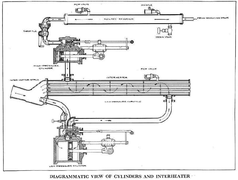 | Left: Operation of Porter two-expansion air locomotive: 1914
|
There are one or two nice technical details; the whistle is fed from the auxiliary reservoir which maintains a good pressure to operate it. There is a drain valve for releasing water from the auxiliary reservoir. Both the auxiliary reservoir and the reheater are fitted with pop safety valves. These are a vital necessity in case the reducing valve should stick open, letting through air at 1200 psi.
 | |
Above: Porter two-expansion air locomotive: 1912
|
 | Left: Triple-expansion loco engine
Three interconnected air-storage cylinders are shown, with a maximum pressure of 150 atm. (2200 psi) The auxiliary reservoir is pressurised at 25 - 30 atm. (370 - 440 psi) At present it is not clear if any triple-expansion locomotives were built. |
The diagram above shows a triple-expansion version of the Hodges-Porter system. The source is currently unknown but is probably Porter literature. Air is shown stored at 150 atm (2100 psi) which is a much higher pressure than normally used, and presumably needed triple-expansion to exploit it properly. This pressure was dropped to 25 to 30 atms (350 to 420psi) by a reducing valve. It is further reduced (by the throttle? though it looks like an ordinary hand valve) to something below 15 atm (210 psi) and enters the HP cylinder, which has a safety valve set to 15 atm on the "steam chest" which is a pardonable error on the part of a draughtsman no doubt more familiar with steam locomotives. The IP cylinder pressure is not shown, but the LP cylinder has a safety valve set to 5 atm. (70 psi) All the references to working Porter air locomotives that I have seen indicate they were double-expansion, and it is not currently clear if triple-expansion was actually used in practice. I suspect not.
2100 psi sounds like a frighteningly high pressure to me, given that steam locomotives rarely exceeded 250 psi; that is probably why three storage reservoirs are shown, as a more economical way to contain such a high pressure. The usual dual-expansion Porter locomotives had a maximum pressure of 1200 psi. One wonders about safety. Of course there was no fire or scale build-up to cause erosion of the metal, but even so, I can't help wondering if any of them blew up. It would be rather important to check the inside of the storage tanks for corrosion due to condensed moisture, I suspect. Note that all the Porter reservoirs have an inspection manhole at one end, presumably for just that purpose.
Some rigorous Googling has failed to find any reports of a compressed-air locomotive exploding. There is a record of an accident at Lambton D pit in County Durham, England when, on 11th June 1881, John Wilson, age 49, a Shifter, "drove away a small locomotive in the pit, something he had no right to do, and it collided with some tubs and crushed him to death." Presumably he was attempting to reverse it and so was at the end which hit the coal tubs.
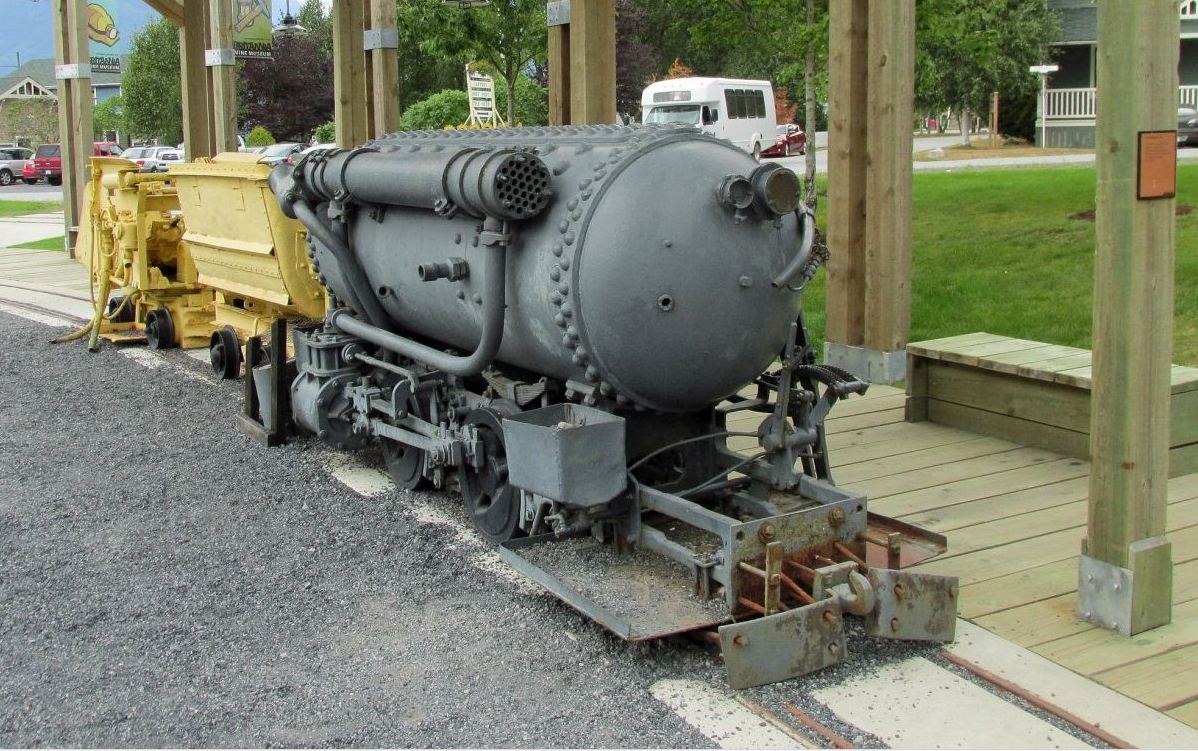
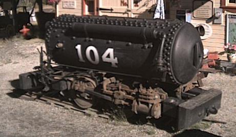 | Left: Porter double-expansion locomotive No 104 with reheat from ambient air: 1910
The long thin cylinder visible on this side of the tank is a reservoir for air at the working pressure of 250 psi, which has been through the pressure reducer from the main tank at 800 psi. The throttle valve is at the front, operated by a handle and linkage from the drivers compartment. Fittings include a pressure relief valve, a brake lever which applies brake shoes to the steel wheels, air operated sanders to maintain traction, and a driver's stand, which is apparently missing- it would have been at the left, where the control levers can be see. This appears to be a Class B-P-O locomotive: see next section. |
Note the large number of very big rivets required to hold the air storage tank together, compared with steam locomotives that worked at a much lower pressure. You may be wondering why the working-pressure reservoir is in the form of a long thin cylinder rather than a more compact tank. I suspect the answer is that the long cylinder could conveniently be made out of a length of standard steel pipe, whereas a stubby tank would suffer much greater hoop stresses and would need to been fabricated with heavy riveting, like the main storage tank. The long cylinder would also have a greater surface area to absorb heat from the environment, which would be useful after the air had been cooled by expanding down to the working pressure.
This locomotive dates back to 1910. It was used at one of the coal mines in Canmore, Alberta, and is on display at a museum in Sandon, British Columbia, Canada, which kindly provided the picture and some of the facts. See: www.sandonbc.ca
A Porter catalogue talks about reheating: "...but there are cases where it is wise and economical to reheat the air before it enters the auxiliary reservoir on its way to the cylinders. The additional efficiency gained by this reheating varies from 35 to 50 per cent..." from "Light Locomotives" by H.K. Porter, 1900
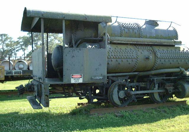
 | Left: Porter surface locomotive, date unknown
|
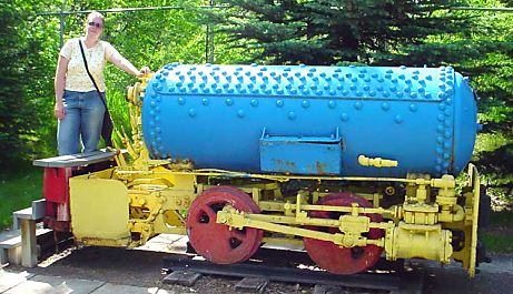 | Left: Another preserved Porter locomotive.
|
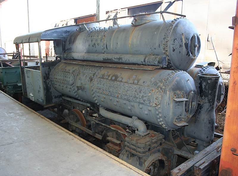
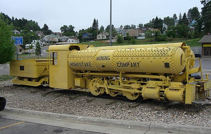 | Left: Preserved Porter locomotive: 1928
|
The Homestake engine has two storage cylinders side by side, because this reduces the hoop stresses in the metal and is therefore more economical to make. The outlet diffuser of a reheater can be seen at the front, with a hood over it; the reheater appears to be mounted between and below the two storage cylinders. Once more this appears to use double rather than triple-expansion of the air. It is somewhat however mysterious why the two tandem cylinders visible at bottom right are of the same diameter; possibly this is the low-pressure side, and tandem cylinders were used to increase the total piston area without exceeding tight limits on side clearance.
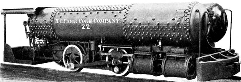 | Left: Porter locomotive for H C Frick
|
The outlet horn of the reheater can be seen at the front between the two tank ends.
H C Frick also bought compressed-air locomotives from Baldwin. (see below)
 | Left: Porter three-tank locomotive: 1915
|
 | Left: Porter three-tank locomotive: 1915
|
I am afraid I have lost the name of the person that sent these last two pictures to me. Please make yourself known if you want attribution.
FROM THE PORTER BOOK: 1914
In 1914 the H K Porter Company published the second edition of their book: Modern Compressed Air Locomotives. This gives a detailed insight into compressed-air technology and economics. The illustrations in this section are taken from that book. The book deals with compound (two-expansion) working, but not triple expansion.
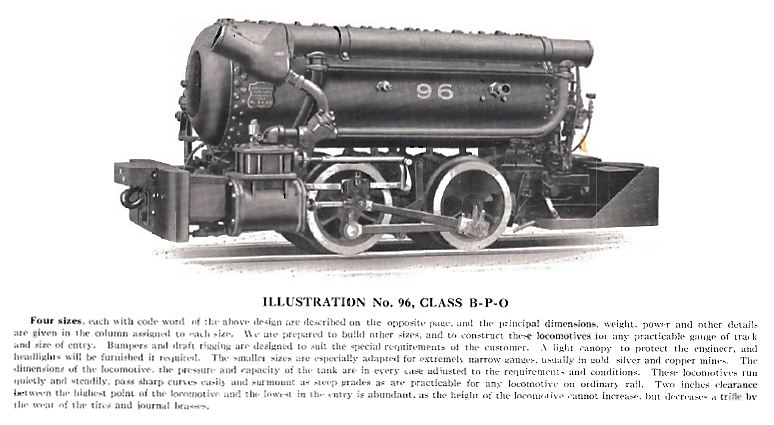 | Left: Porter Class B-P-O air locomotive: 1914
|
 | Left: Porter Class B-PP-O air locomotive: 1914
|
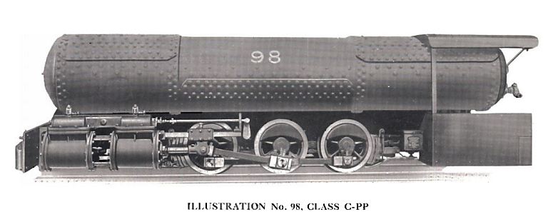 | Left: Porter Class C-PP air locomotive: 1914
|
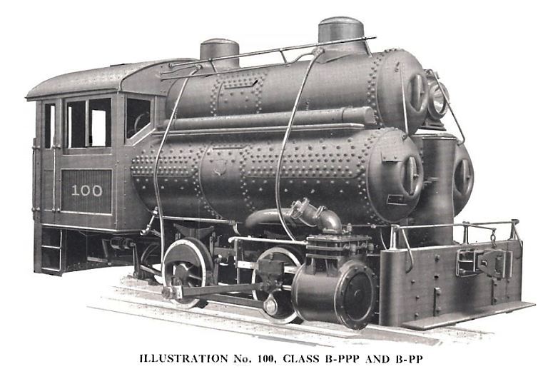 | Left: Porter Class B-PPP and B-PP air locomotive: 1914
|
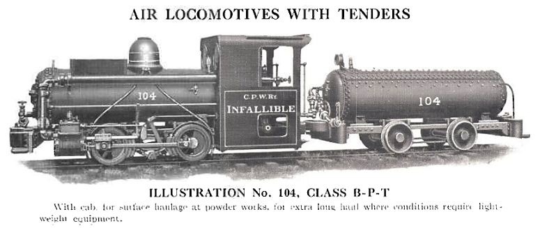 | Left: Porter Class B-P-T air locomotive: 1914
|
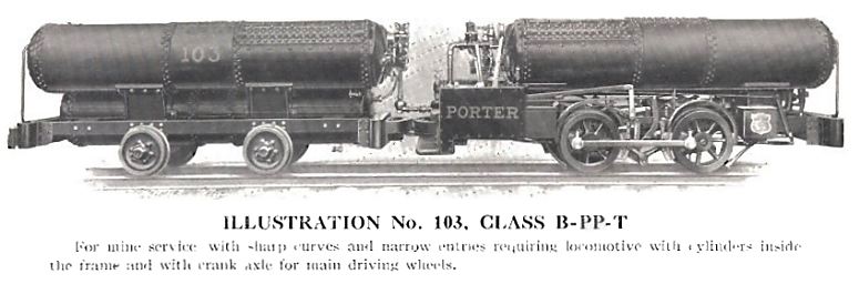 | Left: Porter Class B-PP-T air locomotive: 1914
|
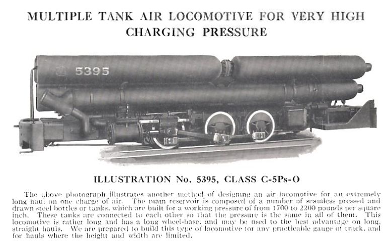 | Left: Porter Class C-5Ps-O air locomotive: 1914
|
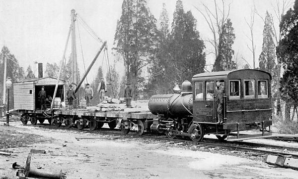
ANOTHER HARDIE COMPRESSED-AIR LOCOMOTIVE: 1897
This seems to be Hardie at work again, some twenty years later with a more advanced design of locomotive. It was intended to run on the Elevated Manhattan Railway in New York, where the ansence of smoke and smuts would have been a major advantage.
 | Left: The Hardie locomotive of 1897
|
 | Left: The locomotive partially assembled.
|
 |  From "Railway and Locomotive Engineering" Volume 10, No 5, May 1897There are a couple of interesting points in the text to the left. Firstly, a full charge of air weighed over 2500 pounds, or 1.1 tons. Air is surprisingly heavy stuff. Secondly, note the claim that the water evaporated in the air heater made up half the volume of the air/steam mixture, so this counts as an aero-steam system. |
 | Left: Side view of the locomotive
|
From Street Railway Journal, May 1897:
"The accompanying engraving (this refers to the side view just above) shows a new compressed air locomotive recently built by the American Air Power Company for the Manhattan Elevated Railroad Company of New York. The locomotive will be put in operation within a few days on the Sixth Avenue division of that company and will operate between Fifty-eighth Street and Rector Street. The wheels are 42 ins. in diameter; the dimensions of the cylinder are 13 ins. in diameter by 20 ins. stroke, and the storage- reservoir has a capacity of 175 cu. ft. This, it is estimated, will allow the locomotive to make the round trip between Rector Street and Fifty-eighth Street with 20 per cent reserve. The reservoir is composed of Mannesmann tubes with a diameter of 9 ins. and having various lengths, from 14 ft. to 20 ft. 6 ins. The thickness of the tube is 9 ins. The tubes are rolled from solid ingots according to the regular Mannesmann process."
"The air is stored in the reservoir at 2000 lbs. pressure. It is used in the cylinder at 200 lbs. pressure with cut-off at 10% stroke. In 5 stroke. Ix passing from the reservoir to the cylinder it traverses the usual hot water reheater and enters the cylinder at a temperature of from 200 to 300 degs. The water is kept heated by a small coal fire. But little fuel is required to maintain this, as will be appreciated when it is stated that only an ordinary scuttleful of coal is carried by the engine. A novel feature of the engine, as will be seen, is the location of the cylinder. This is directly under the cab, giving a short lead for the heated air. The valve mechanism is extremely simple and can be seen in the engraving under the cab. It is operated by the wheel which can be seen through the window of the cab. The weight of the entire locomotive equipped is 47,000 lbs. The power station will be located at 100 Greenwich Street."
 | Left: Another side view of the locomotive
|
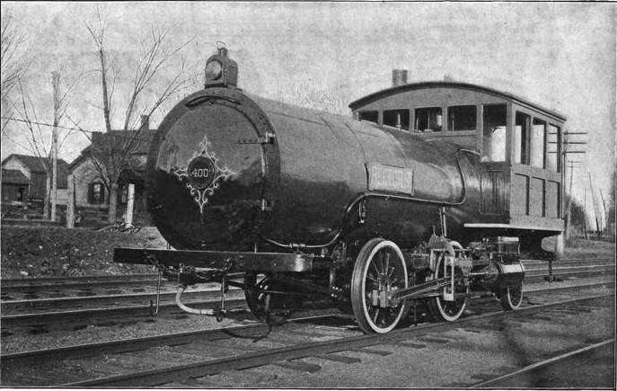
THE DICKSON COMPRESSED-AIR LOCOMOTIVE: 1899
Above: This 0-6-0 locomotive was built for coal mining by the Dickson Locomotive works at Scranton, Pa, USA. The picture dates from 1899.
The difference between the storage and working pressure indicates that a reducing valve was used between the tank and the engine cylinders. Note that 600 psi is a much higher pressure than normally used in steam boilers, which rarely exceeded 250 psi. This is why the tank shown above is studded with very big rivets, compared with a steam boiler. This is characteristic of air locomotives.
BALDWIN COMPRESSED-AIR LOCOMOTIVES
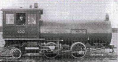
Baldwin are very well-known as makers of steam locomotives, but they made air locomotives too. In 1897 a compound 0-4-0 locomotive was designed by Baldwin's chief engineer, S M Vauclain, for the Philadelphia & Reading Coal & Iron Company for use in their Alaska Colliery. (This appears to have been in Pennsylvania rather than the frozen north) It was successful and three more were ordered.
The Baldwin designs look rather basic compared with the ingenious reheating system used by Porter. So far as current knowledge goes, Baldwin never attempted anything like this, probably because the idea was tied up by Hodge's patents. (See the Porter engines above)
This is one of the Philadelphia & Reading Coal & Iron Company locomotives, judging by the letters on the tank.
This looks like a compound engine, with the larger LP cylinder above the smaller HP cylinder, their pistons moving together. It appears the valve assembly is above the LP cylinder.
Note the fins on the cylinder assembly, intended to absorb heat from the environment and reduce the cooling of the air when it expanded.
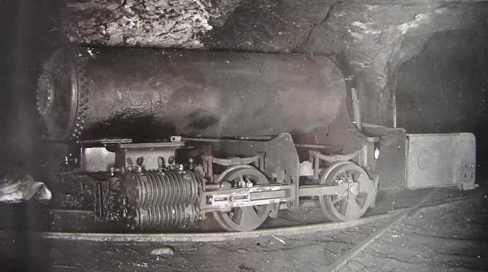
This is believed to be one of the Philadelphia & Reading Coal & Iron Company locomotives underground. Note the distictive two-section balance weights built into the wheels.
This machine appears to be in a sorry state, with the valve assembly above the cylinders missing.
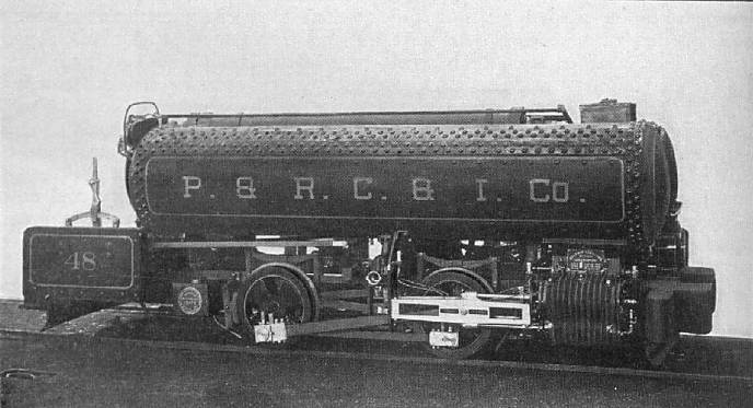
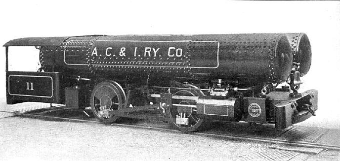
A compressed air locomotive built for the Ashland Coal & Iron Railway co. by the Baldwin locomotive works of Philadelphia, date unknown.
There are three storage tanks. Only two are visible; a smaller third tank is mounted between the frames. One of the two upper tanks is shorter than the other, to make room for the very cramped cab. The ends of the tanks appear to be dished inwards to better resist the internal pressure.
Air was stored at 600 psi, and was used at 100 psi. The engine required a vertical clearance of 5 feet, and 6 feet in width. It would take curves of 30-foot radius. There only seems to be one cylinder visible so this appears to be a simple-expansion design.
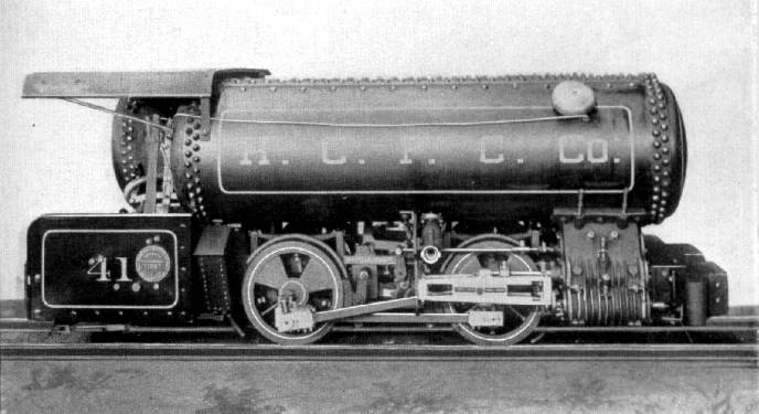
A compressed air locomotive built for the H. C. Frick Coke Co. by Baldwin, date unknown.
Number 41 was a 40" gauge locomotive. It is believed to be a compound with 3.75" & 6" diameter cylinders of 10" stroke, with 24" driving wheels. The tank nearer the camera is shorter to allow room for a cab, and carries a warning gong.
The Baldwin works number was 17857 06-00. Air storage and use pressures unknown.
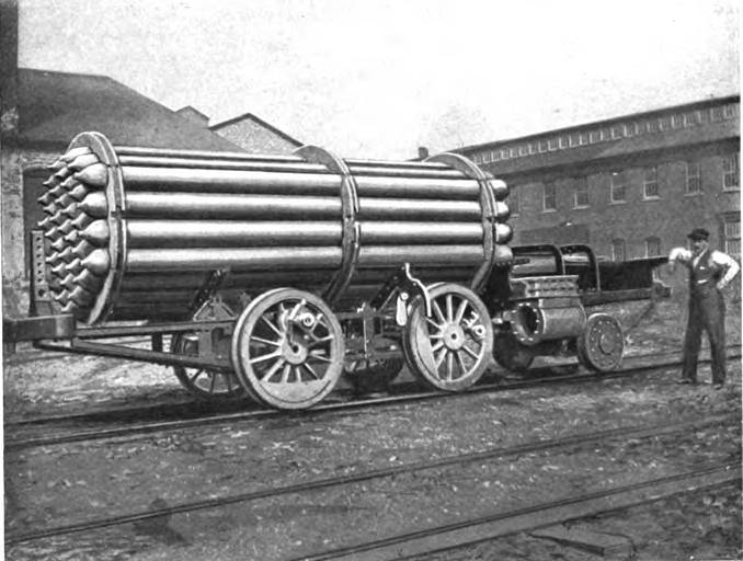
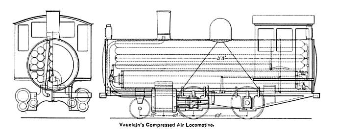
This diagram illustrates the application of an air heater patented by Vauclain.
Air was stored in a number of small-diameter cylinders rather than large tanks, as for the Hardie locomotive above.
From American Engineer and Railroad Journal, February 1899, p58
I haven't done the calculations, but I would have thought that the use of a number of small-diameter cylinders (apparently 24 of them) rather than one or two large tanks was an inefficient use of metal. A reducing valve at the front of the cylinders admits air into the large cylinder just above the chassis, which is an air receiver surrounded by a cylindrical hot-water drum. Some of the water was sprayed into the central air receiver to improve the heating and help lubricate the cylinders; for this to work I imagine the hot-water drum must have been pressurised by air from upstream of the reducing valve. The hot water was provided from an external source, and this seems like a serious drawback, as it would presumably need to be changed frequently, and probably much more often than the air tanks need to be refilled.
Note the exhaust pipe directed up the chimney.
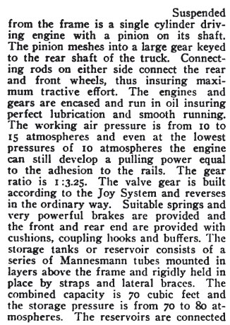
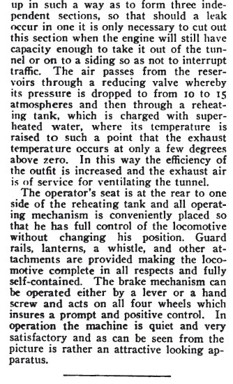
THE SIMPLON TUNNEL LOCOMOTIVES
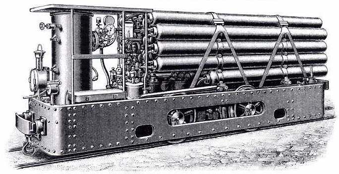
The Simplon Tunnel links Switzerland and Italy, running beneath the Alps. Construction began in 1898 and the tunnel was opened in 1906. Some sophisticated compressed-air locomotives were built for the tunnel construction by the Swiss Locomotive Works in Winterthur.
Here a large number of small-diameter tubes were used for air storage, suggesting that the pressure used was high. They were not afraid of high pressures at Winterthur.
The vertical cylinder on the left is the reheating tank for the air. In the article below it is stated that the tank was filled with superheated water, ie water that would flash into steam if were not under pressure. This increased the thermal storage capacity of the water; it would be interesting to know what water pressure was used.
This is from an article in Compressed Air Magazine in 1902. The first part of the article is of little interest so I have just reproduced the technical stuff here.
Note the working pressure was 147 to 220 psi, while the storage pressure was from 1028 to 1175 psi; which is about half that of the Hardie locomotive described above, which used 2000 psi.
Note also that this locomotive was unusual in having a single cylinder geared to the rear axle. I would have though this would have caused dead-centre problems, but no mention of this has been found so far.
From Compressed Air Magazine for July 1902, Vol 7 No 5, p1906
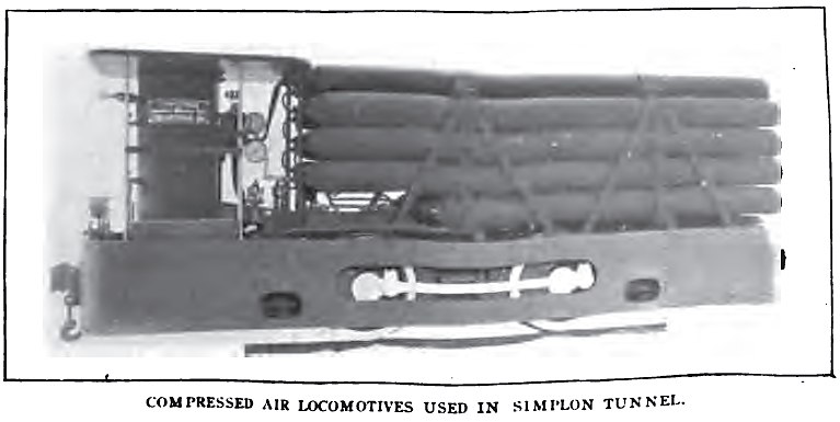
This is the only photograph of a Simplon locomotive found so far. Sadly it is of poor quality and the image has become deformed at some point.
From Compressed Air Magazine for July 1902, Vol 7 No 5, p1906
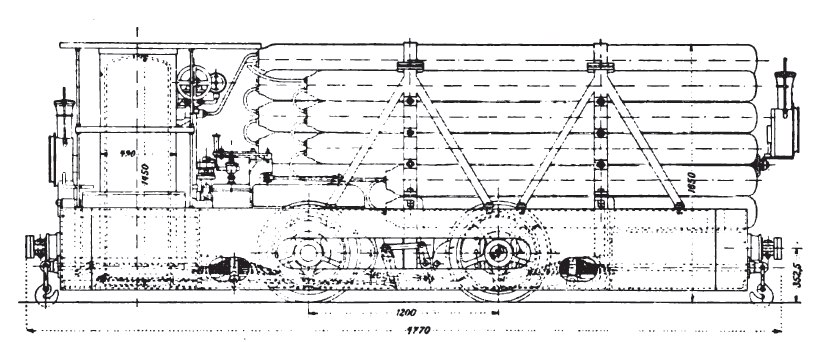
Side elevation of the locomotive. The lower storage cylinders are shorter to allow room for the engine.
From Compressed Air Magazine for July 1902, Vol 7 No 5, p1906
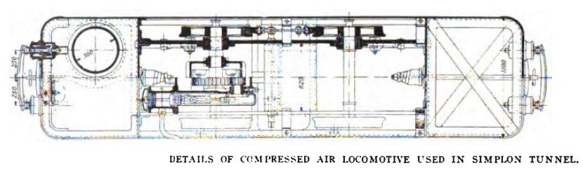
Plan of the locomotive. The engine and its gearing can be seen in the lower half of the drawing, left of centre.
From Compressed Air Magazine for July 1902, Vol 7 No 5, p1906
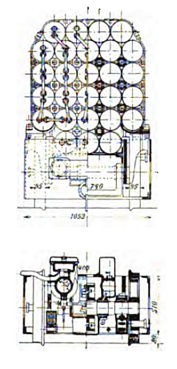
Top: end elevation showing the linking of the storage cylinders.
Bottom: cross-section through locomotive showing engine cylinder
From Compressed Air Magazine for July 1902, Vol 7 No 5, p1906
The material from Compressed Air Magazine was kindly provided by Mark Lundquist.
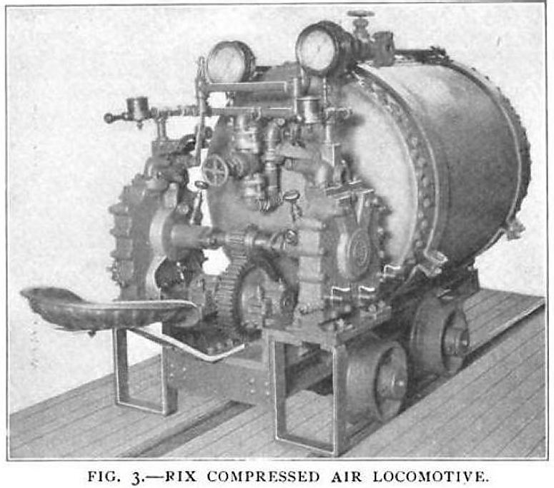
RIX COMPRESSED-AIR LOCOMOTIVES: 1902
This remarkable locomotive is powered by two square-piston engines, one each side of the frame, coupled together and driving a layshaft through spur gearing. This then presumably drives the rear axle, though quite how this is done is not visible. This is clearly a very small locomotive, judging by the size of the seat at left, and and there is no room for conventional cylinders and pistons.
This looks like a dangerous piece of machinery to operate. That unguarded gearing is enough to worry any man.
The engines are clearly Dake square-piston engines, identified by the V-shaped steam channels on the outer side of the casing. There appear to be three small drain taps at the bottom of the nearest engine.
I am glad to report that the Rix company still exists: rixindustries.com.
From Compressed Air Magazine Jan 1902 (No 11 Vol 6).
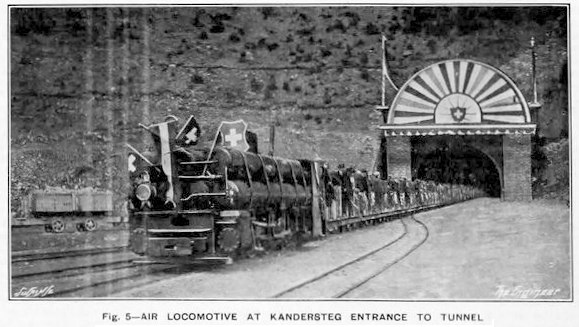
COMPRESSED-AIR LOCOMOTIVES IN THE LOTSCHBERG TUNNEL: 1907-1913
The Lötschberg Tunnel is a 9 mile long railway tunnel on the Lötschberg Line, connecting Spiez and Brig at the northern end of the Simplon Tunnel in Switzerland. Work began in 1907 and finished in 1913. Its construction was marked by several serious accidents; in the worst, on the 24th July 1908, the tunnel broke through into a flooded valley that was much deeper than expected and killed 25 out of 26 miners. This is known as the Lotschberg Tunnel Disaster.
This photograph of a celebration train was taken in March 1911 when the tunnel was holed through.
Five compressed air locomotives were used in the tunnel, and it at first seemed likely that these were the same machines that had been used in the Simplon tunnel, which opened in 1906; However, the storage cylinders are clearly quite different. Confirming this, The Engineer for 8 Dec 1911 says the Lötschberg locomotives were made by Thebault, of Marly, France, and not at Winterthur like the Simplon locomotives.
From: Railway Wonders of the World - Volume 1 - Page 109 by Frederick A Talbot
Two large engines with eight coupled wheels and seven storage cylinders of 7.5 cubic metres total capacity were employed for work outside the tunnel. The next smaller size, of which there were again two, were used for the masonry sections inside the tunnel; see photo above. The fifth and smallest locomtive was used for the dressed sections of the advance heading, had four-coupled wheels and a storage capacity of 3 cubic metres. The working pressure of the locomotives was 120 bar. (1740 psi)
Compressed air for the locomotives was supplied by compressors made by Meyer, of Mulheim. There were two, each of the 400 horse-power two-cylinder duplex type. The main reservoirs for the locomotive air were supplied with 0.3 cubic metres of air per second at 120 bar. The compressors were powered by electric motors, in turn powered by hydro-electricity generated remotely by Pelton wheels.
Regrettably this photograph is of poor quality. It is possible to make out horizontally-stacked storage cylinders and their connecting pipework and the oil lamp on the front. The cab is presumably at the other end, where the man is standing, apparently with one foot on the footplate.
From: Railway Wonders of the World - Volume 1 - Page 109 by Frederick A Talbot
USA COMPRESSED-AIR LOCOMOTIVES IN THE ROVE TUNNEL: 1916
This dramatic illustration shows a four-tank compressed-air locomotive at one of the portals of the Rove Tunnel, a 4.5-mile canal tunnel built between 1911 and 1916 in France to allow the Canal de Marseille au Rhône to reach Marseille harbor. It is the longest canal tunnel in the world.
No information about the locomotive has so far been unearthed, but I suspect that the prominent exhaust horn (at the front of the locomotive) marks it as a Porter design. It is difficult to be sure from the illustration, but it is possible that there were actually four top tanks, making six altogether. The top tanks appear to be longer than the lower ones, extending back over the heads of the driver and his mate.
In 1926, after twenty years of work and World War I, the Rove tunnel was finally opened for use, surviving only forty years (a very short time for a canal tunnel) before suffering a collapse and being abandoned for traffic in 1963.
The French Wikipedia has more details of the Tunnel du Rove, but not unnaturally the text is in French.
The artist may have let himself get a bit carried away here- if the locomotives run on compressed air, why is steam drifting out of the tunnel?
Scientific American, 25 Nov 1916
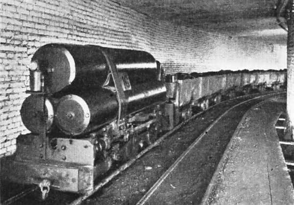
UNIDENTIFIED COMPRESSED-AIR LOCOMOTIVE: 19??
This photograph comes from the early 20th century, but nothing else is known. The location appears to be Europe.
At the front of the locomotive is a white shape which is almost certainly ice that has formed on the cylinder, showing that the locomotive was in use at the time.
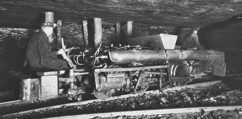
THE HUDSON COAL COMPANY COMPRESSED-AIR LOCOMOTIVE: 193?
Nothing is known about this machine except where it was used.
It looks very much like an improvised one-off, constructed with several long cylinders to hold the air.
At its peak the Hudson Coal Company employed ten thousand men at its fourteen anthracite mines in Pennsylvania. By 1940 it had installed 650 miles of underground track on which it ran 275 electric locomotives and also kept 1,100 mules in underground stables to pull coal trucks when required; presumably any compressed air locomotives had been disposed of by this date. At one time the Hudson was a subsidiary owned by the Delaware and Hudson Railroad Company.
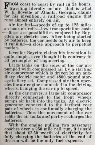
The basic propulsion of this piece of eccentricity was by big tanks of compressed air. That would not have got it very far, and certainly not from coast to coast of the USA.
However, the phrase "perpetual drive" in the title explains everything. The stored air used by the air engine is replenished by a wheel-driven air compressor. I hope I don't need to explain that this is a crude attempt at perpetual motion without the faintest possibility of working. It does not appear to have been an attempt at regenerative braking.
But the inventor did not stop there. Oh no. There is a second perpetual motion system in which a wheel-driven electrical generator charged a bank of batteries (4800 pounds of them) which drive an electric motor which drove another compressor to keep the air tanks topped up. This is of course even madder than the first system because of the extra losses in the generator, batteries, and electric motor.
The main interest in this story is in speculating how Mr W E Boyette managed to convince himself that it would work, for long enough to finance and build this monster. The writer of the article wasn't fooled- he nails it as "contrary to all principles of engineering" and I couldn't agree more.
A point of detail: just below the man's lifted leg is what looks like a conventional steering link to the front wheels. Was it supposed to travel off-rail in some way?
Note the extraordinarily optimistic estimate of running costs at the end of the text.
He didn't think it through, did he? (with apologies to Al Murray)
Another view of the Boyette monstrosity, this time from Popular Science, who stated it was about to undergo a trial run between Atlanta and Jacksonville, Florida.
In this picture what appears to be a V-twin compressor (or air engine?) can be seen under the bonnet.
GERMAN COMPRESSED-AIR LOCOMOTIVES IN 1951
Pneumatic locomotives often used multiple cylinders for air storage, rather than one large tank. It reduces the stresses in the metal and is therefore more economical to make. Note the unequal sizes of the cylinders used here.
This locomotive was pictured in a book published in 1951, but it looks primitive compared with the 1955 model below.
According to Prof Statham, air locomotives were not used in British mines. (Presumably he meant in 1951, for they were certainly used in Britain before 1900) They were however extensively used in the Ruhr coal-field in Germany, the number in use rising from 617 to 1223 from 1919 to 1940. Compressed air was produced at the surface by multi-stage compressors, and sent underground via pipes from 1.125 to 2 inches in diameter. The pressure used was from 1800 to 3000 psi. The range of the locomotives used was from 2.5 to 6 miles; charging stations were set at intervals along the mine roadways. From one to nine storage cylinders were used, and the charging time was from 1 to 2 minutes. The smaller engines weighed 6 tons and developed 14 HP, while the larger weighed 10 tons and gave about 40 HP. The usual speed was 6 - 7 MPH, and the tractive effort varied from 990 to 23360 pounds when starting, and 530 to 1700 pounds when running at normal speed.
Prof Statham was not impressed by air locomotives. He states that they are inefficient, (unarguable, due to the heat lost when compressing air) and noisy. (Though surely some sort of silencer could be used? Car silencers seem to do a good job without causing excess back pressure) He also claims that capital and running costs were high. Capital costs may well have been high, as these locomotives were made in relatively small numbers, with not much economy of scale. As to the running costs, perhaps he was thinking of the inefficiency, as there seems to be no reason why much in the way of maintenance would be required. Certainly much less than for steam engines.
THE JUNG COMPRESSED-AIR LOCOMOTIVE: 1955
This pneumatic locomotive also uses multiple air cylinders, but this time they are all the same size.
Note that the storage pressure has risen by a factor of five compared with the Dickson locomotive above.
ON THE COMPRESSION OF AIR
It is a sad fact of life that all the heat generated when compressing air is lost, and cannot be reclaimed. The energy required can how ever ne reduced by doing the compressing in two or more stages, with cooling of the air between stages. According to Porter's book, (1914) multistage compression came into general use around 1890, and compressors for charging locomotives used three or four stages with inter cooling. This was said to reduce the heat losses from 96% to 17%, assuming isothermal compression.
EXTERNAL LINKS
Compressed air vehicles in general: aircaraccess.com
For French references, Google on "locomotive ŕ air comprimé". For example:
tramways_mecaniques
Porter locomotive links:
Storage Pressure
600 psi
Working Pressure
150 psi
Tank capacity
170 cu ft
Weight
16 tons
Left: Baldwin Compressed-Air loco for the P&RCI
Left: Baldwin Compressed-Air loco for the P&RCI
Left: Baldwin Compressed-Air loco
Left: Baldwin Compressed-Air loco
Left: Baldwin Compressed-Air loco with heater: 1899
Left: Simplon locomotive: 1902
Left: Simplon locomotive: circa 1900
Left: Simplon locomotive: 1902
Left: Simplon locomotive: 1902
Left: Simplon locomotive: 1902
Left: Simplon locomotive: 1902
Left: Rix air locomotive: 1902
I have not so far been able to get hold of the text of this article; can anyone help?
Left: Medium-sized compressed-air locomotive at Lötschberg: 1907
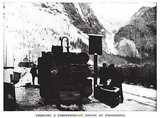
Left: Recharging a compressed-air locomotive at Kandersteg: 1907
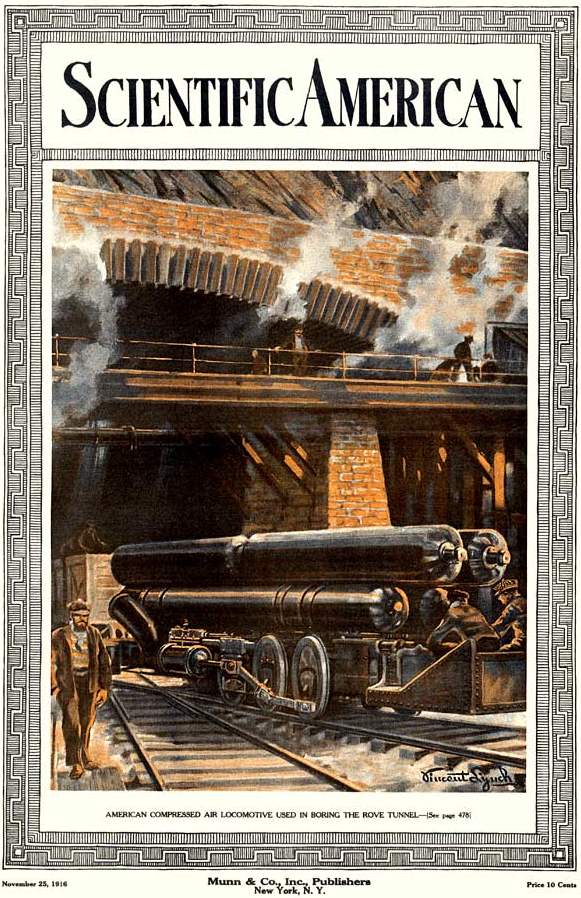
Left: American compressed-air locomotive: 1916
This appears to be a very large locomotive compared with other designs on this page.
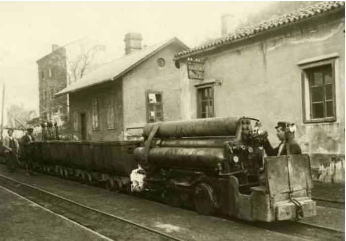
Left: Unidentified Compressed-Air Locomotive: 19??
Left: Hudson Coal Company Compressed-Air Locomotive: 193?
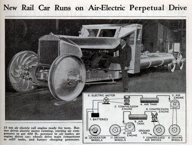
Left: The Boyette Compressed-Air Railcar: 1934
From Modern Mechanix Feb 1934
Left: the incriminating details
From Modern Mechanix Feb 1934
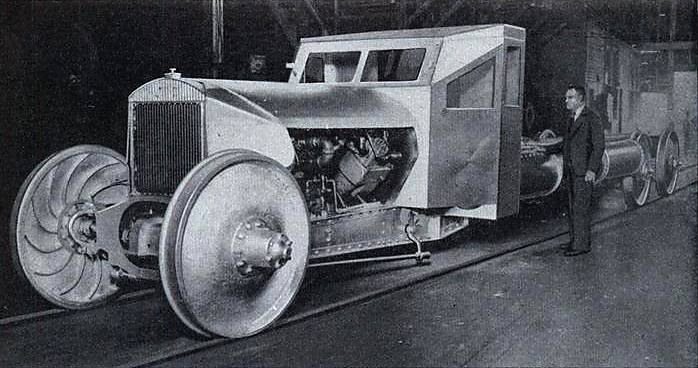
Left: The Boyette Compressed-Air Railcar: 1934
From Popular Science Feb 1934
Left: This is believed to be a German mine locomotive: 1951?
From Coal-Mining by I C F Statham, Professor of Mining, University of Sheffield. Published 1951 by English Universities Press
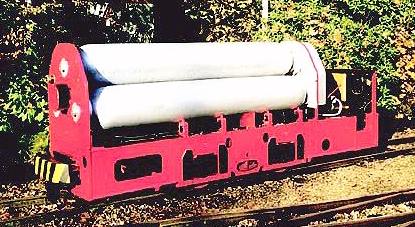
Left: A slightly more modern pneumatic locomotive, the Jung PZ 20 Preßluft-Grubenlok, or "compressed air pit locomotive", built in 1955.
Pressure
2900 psi
Power
20 HP
Weight
5.6 tonnes
Interesting historical material, but some worrying references to what appears to be perpetual motion.
![]()
