Gallery opened 20 Apr 2018
Updated: 30 Mar 2019
Comparison of machines (T & W Cole)
Refrigeration the safe way


Refrigerating with air |
Gallery opened 20 Apr 2018 |
Refrigeration may not be a glamourous area of technology but it is of vital economic importance. On the large scale it means frozen food can be transported around the world; on the small scale it means we don't have to go shopping for perishable food every other day.
MODERN REFRIGERANTS
The well-known refrigerating agents today are ammonia, for commercial operations, hydro-flurocarbon compounds (HFCs), hydrocarbons such as butane and pentane, and air and water. In case you are wondering about the last two, air is used as a refrigerant in air-conditioning machines for aircraft, fed by bleed air from the jet engines. Water is used as a refrigerant in static air-conditioning systems.
Ammonia is known to be dangerous. It is poisonous and explosive in air in some proportions. You might think that by this time the dangers of ammonia had been completely conquered, but you would be wrong. This accident in August 2013 in China killed 15 people and injured 26.
HFCs are used because they do not contain chlorine and so do not affect the ozone layer. A release into a confined space can cause asphxiation, as is true of any gases except air and oxygen.
Any sort of inflammable refrigerant presents a risk of explosion. There have been recent reports of domestic butane refrigerators exploding due to leaks.
All the dumped refigerators that I've seen recently have had 'Pentane' written on the back. Pentane has a flash point of -49 degC and ignites easily. Pentane is apparently being replaced by propane in this application.
HISTORICAL REFRIGERANTS
Are many in number, including CFCs, sulphur dioxide, carbon dioxide, ethyl chloride, methyl chloride, methyl formate. Ethane (C2H6), propane (C3H8), butane (C4H10), iso-butane ((CH3)3-CH), methyl-ether (by Tellier) and diethyl-ether () have all been used as refrigerants in the past.
Into this category comes methyl chloride, and some of the hydrocarbons.
CFCs (Freons) are non-toxic but some of them have disastrous effects on the ozone layer when released and they are now banned.
Sulphur dioxide causes severe respiratory irritation and is toxic.
Old refrigeration textbooks are prone to say things like "carbon dioxide is completely safe" which is clearly untrue because of the suffocation hazard if a lot of it is released in a confined space
Any sort of inflammable refrigerant presents a risk of explosion. Into this category comes methyl chloride, and the hydrocarbons. Ethane, propane (C3H8), butane (C4H10), and iso-butane () have all been used as refrigerants in the past. There is a Wikipedia page on Refrigerants
Several early vapour compression machines used diethyl ether as a refrigerant; it is suitably volatile and as chemicals go was reasonably cheap, being made simply by the action of sulphuric acid on ethanol. Ether is of courser highly inflammable, and its heavy vapour tends to accumulate alarmingly in low places. But perhaps its worst characteristic is that of spontaneous explosion when ether peroxides are formed. The Museum page on ether as a working fluid in engines warns that:
Diethyl ether oxidises and polymerises in the presence of air, creating the interesting compound diethyl ether peroxide (-CH(CH3)OO-)n. This is a colorless oily liquid that is an extremely brisant (fast-exploding) and friction-sensitive explosive; less than 5 milligrams can damage chemical apparatus. The dangerous properties of ether peroxides are the reason that the use of diethyl ether and other peroxide-forming ethers like tetrahydrofuran (THF) or ethylene glycol dimethyl ether (1,2-dimethoxyethane) is carefully avoided in industrial chemical processes.I am certainly not an expert on ether chemistry, but continuously reboiling ether sounds like it might be a good way to generate the peroxide. Peroxides generally have higher boiling points than the compounds they come from, so if an ether mixture is heated, the peroxide can become progressively more concentrated in the boiler and the risk of explosion increases rapidly. |
Looking at these dire warnings it appears puzzling that anyone was able to operate an ether vapour-compression machine without blowing themselves to Kingdom Come. I suspect the answer is that in a refigerator you can arrange for every part to be under pressure, so air cannot seep in even if there are small leaks, and peroxides cannot form.
This is not remotely a comprehensive list. You can find a daunting array of refrigerants in Wikipedia; most of them are only relevant to vapour-compression cycles.
Table of Wikipedia links to the more common refigerants:
Ethane
Methyl formate
Butane
Methyl chloride
Pentane
CFCs
Dimethyl ether
HFCs
Diethyl ether
Methylene chloride (called carrene in the trade). |
Bearing in mind all these various hazards, air and water as refrigerants have the attraction of being completely safe. Unfortunately they are also inefficient at refrigerating, and in the case of air its low heat capacity means that large volumes have to be handled. Air must be the ultimate safe refrigerant, (A water-based refrigerator could conceivably drown you) and that is one reason why it is worth looking at. Air has the further advantage that it wil not react with lubricants.
However, nothing is wholly risk free. A cold-air machine involves significant pressures, and something might be overstressed and fracture violently. Compressing air carrying a lot of lubricating oil could lead to a Diesel-type explosion.
THE EARLY HISTORY OF REFRIGERATION
The best-known refrigerating method is the vapour-compression refrigerator. This relies on a refrigerant like ammonia which liquefies easily when compressed and as a result is greatly cooled when passed through a throttling valve.
The prolific Ametrican inventor Oliver Evans described a vapour-compression refrigerator in 1805 but appears to have made no attempt to build one.
The first vapour-compression refrigerator was patented in 1835 by Jacob Perkins, but not commercially exploited. It used diethyl-ether or "some other volatile liquid" in a closed cycle.
The first commercial use of the vapour-compression refrigerator was achieved by James Harrison, whose first mechanical ice-making machine began operation in 1851 on the banks of the Barwon River at Geelong, in Australia.[3] His first commercial ice-making machine followed in 1854, and his patent for an ether vapor-compression refrigeration system was granted in 1855.
COLD-AIR REFRIGERATION
It is not possible to make a vapour-compression refrigerator using air because air cannot be liquefied at any reasonable temperature and pressure. (The conditions are quite different in machines specifically dsigned to liquify air) Therefore little or no reduction in temperature occurs on passing compressed air through a throttling valve. Instead work must be removed from the compressed air by making it drive a reciprocating engine or turbine. The use of an expanding engine is not merely a cunning way to reduce the power required to drive the process; it is essential for it to work at all. The work from the engine is used to help drive the compressor, improving the efficiency, but an air refrigerator can never be as efficent as vapour-compression refrigerator; it may not be 1/10 as efficient. Refrigeration engineers prefer to talk in terms of Coefficent Of Performance (COP) rather than efficency because it often comes out as greater than unity, and 'efficencies' of better than 100% have a long and dishonourable association with perpetual-motion nutcases.
The passages quoted below are from an article in Engineering for 4th Feb 1881, which was a report on a long and comprehensive paper given by A Mr Lightfoot, an employee of Messrs J & E Hall and Co, of Dartford- who were at the time much engaged in the manufacture of cold air machinery to be used for the importation of frozen meat from Australia, a very important trade. J & E Hall of Dartford was founded in 1785.
Cold-air machines had considerable advantages for the frozen meat trade. Suppose you used ammonia instead; a leak could be catastrophic in confined spaces, and if the refrigerant was lost there was no way to replace it and the entire cargo would rot. The latter problem was presumably eased when it became possible to store gases at high pressure in steel cylinders.
Home refrigeration became widespread in the 1930s with the introduction of Freon. Housewives could make their favorite meatloaf recipe and store the leftovers for several days time. Meatloaf recipes became a staple in the 1930s due to the difficult financial times during The Great Depression.
GORRIE'S COLD AIR MACHINE
Dr John Gorrie of Florida in 1851 invented a cold-air machine for ice-making. The hot climate of Florida meant that ice was in much demand, and its distance from ice-exporting countries like Canada made ice expensive.
 | Left: Gorrie's cold-air machine: 1851
|
SIR WILLIAM SIEMENS CONTRIBUTES
Sir William Siemens was one of the great pioneers of refrigeration, though he did not design a machine himself. In July 1857 Siemens completed an analysis of Gorrie's cold air machine. He pointed out that Gorrie's machine would more efficient if the exhaust cold air was used to cool the air going into the compression cylinder, and took out provisional patent No 2064. (1857) Siemens is regarded as the inventor of the counter-flow heat exchanger.
Siemen's second criticism of the Gorrie machine was the presence of a throttling valve before the expansion cylinder; this would have given little or no drop in temperature, but by reducing the air pressure reduced the amount of work that could be removed from the air by the expansion cylinder.
Siemen's third criticism related to the problems that would be caused by moisture in the cooled air freezing.
KIRK'S AIR MACHINE
"Kirk's machine consists in principle of a single cylinder in which air is compressed at one end and expanded at the other. The beat caused by compression is partially carried off through the cylinder cover, which is water-jacketted, and the cold from expansion is used to abstract heat from a current of brine or other medium, circulating over the cover at the expansion end. Between the two ends is a regenerator, formed of several thicknesses of wire gauze. Through this both the hot compressed air and the cold expanded air pass, on their way from one end of the cylinder to the other; so that there is a continual alternate compression and expansion of the air, and a continual beating and cooling of the regenerator."
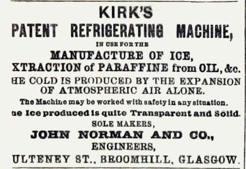 | Left: Advert for Kirk's cold-air machine in 1872
|
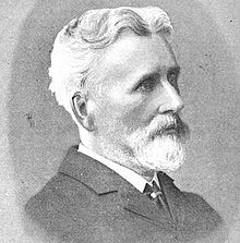 | Left: Dr Alexander C Kirk, 1830-1892
|
Kirk has a Wikipedia page, on which it is suggested that the original refrigerant was indeed diethyl ether.
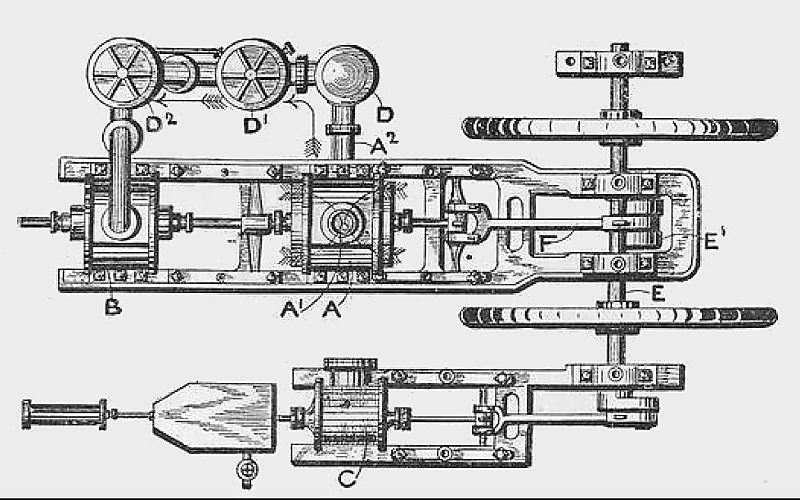
THE GIFFARD MACHINE
"The Giffard cold air machine consists of one single-acting water-jacketted compression cylinder, and one single-acting expansion cylinder, both worked from cranks on an overhead shaft. The compressed air is led from the cylinder into the air cooler, which is merely a cluster of small tubes placed vertically in a case. The cooling water passes upwards outside the tubes, and thence goes to the compression cylinder jacket; the air is admitted into a casing below the ends of the tubes, passes up through them, and is taken off from the top to a wrought iron reservoir. A pipe from this reservoir supplies the air to the expansion cylinder; the admission and exhaust being controlled by two independent steel mitre valves in the cylinder bottom, worked by cams from the shaft. In this machine no attempt is made at drying the air; all the moisture taken into the compression cylinder is discharged in the form of snow from the expansion cylinder, with the exception of the portion deposited in the air cooler owing to the partial cooling of the compressed air."
 | Left: The Giffard cold-air machine: 1873
|
 | Left: The Giffard cold-air machine: 1877
|
GIFFARD MACHINES OF THE GENERAL ENGINE AND BOILER COMPANY
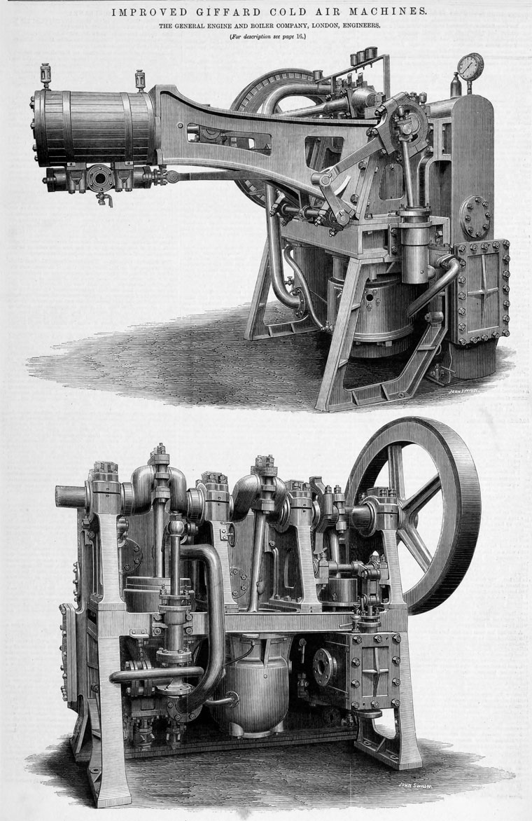 | Left: Giffard cold-air machine: 1883
The top machine has two squat vertical cylinders that constitute the cold-air machine. This is powered by a horizontal steam-engine that for some reason is cantilevered up in the air. The valvegear is just underneath the insulated steam cylinder; it is driven by a big eccentric on the nearer end of the crankshaft, via a rocking arm. Next to the eccentric a small crank drives a water-pump. The bottom machine appears to have no steam engine integrated with it, possibly being driven by the shaft at left. The squat cylinder in the centre is probably the compressor cylinder, as it appears to have a water-jacket to improve the efficiency of compression. |
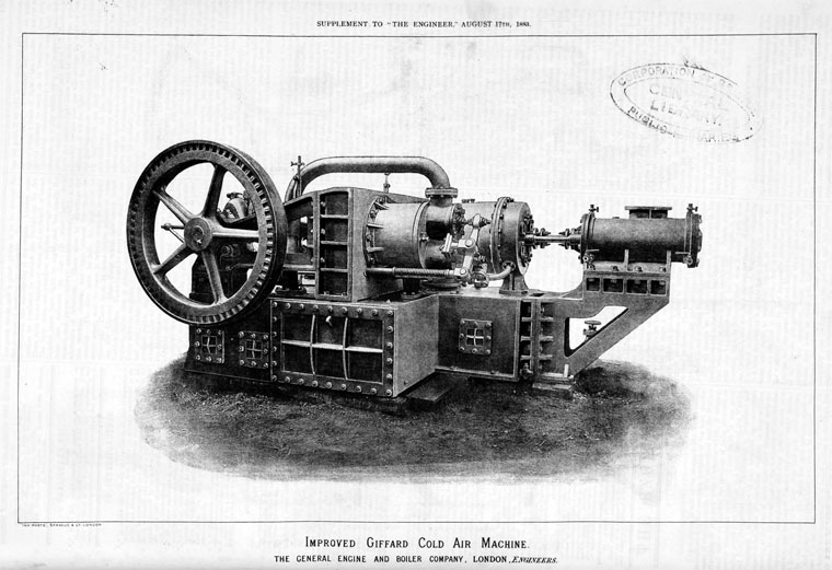 | Left: Giffard cold-air machine: 1883
|
WINDHAUSEN'S MACHINE
"Windhausen's machine expands air from its ordinary atmospheric pressure under a piston; the cooled and expanded air being discharged much below the atmospheric pressure, either through tubes surrounded externally by brine, or into a hermetically sealed chamber, where the objects to be frozen are placed. After this process the air is again compressed to atmospheric pressure, cooled, and re-expanded. The disadvantages of this machine are the large size of the cylinders, &c, necessitated by the very low pressure employed, and the fact of its entirely depending for its action on the production of a partial vacuum."
 | Left: The Windhausen cold-air machine: 1883
|
STURGEON'S REFRIGERATOR
"Sturgeon's refrigerator is a horizontal machine with some novel arrangements as regards the construction of its air-valves and pistons. The compressed air is first cooled partially by being passed through tubes sunounded by cooling water, an then passed through charcoal or some other absorbent of moisture, before being admitted to the expansion cylinder. If the charcoal or other material is properly changed and renewed when necessary, this may form a dry air process; but, as already stated, the introduction of a chemical drier is in the author's opinion undesirable, except under special conditions."
Sturgeon and his refrigerator may have been known to Mr Lightfoot but they are unknown to Google. No illustration of the machine has so far been found.
HICK, HARGRAVES, AND CO
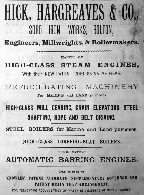 | Left: Advert for cold-air machine: 18??
|
THE J & E HALL MACHINES: 1881
Messrs J & E Hall and Co were the employers of Mr Lightfoot, who wrote the comments in quote marks on this page. He later branched out on his own.
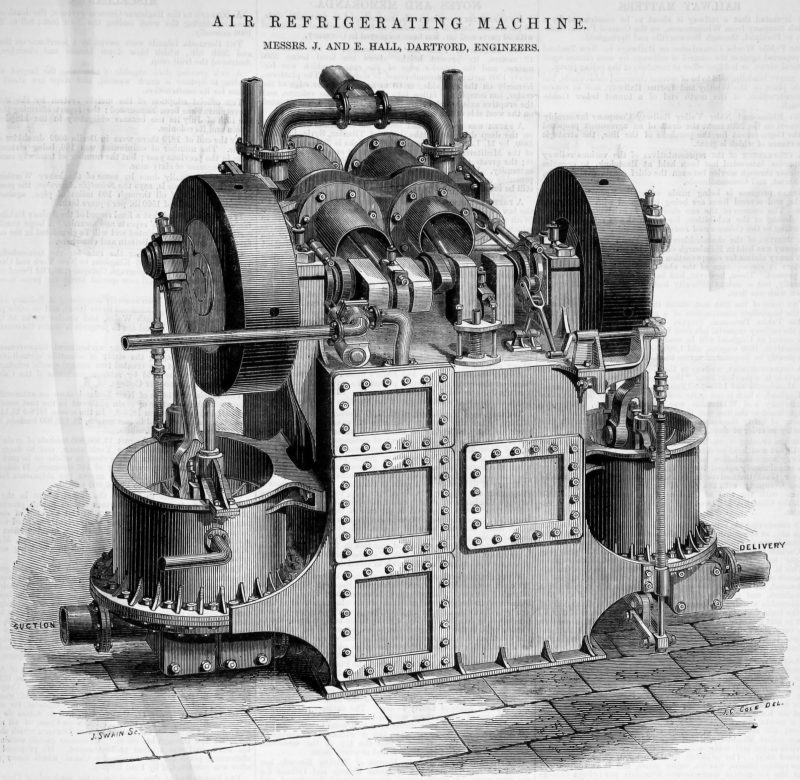 | Left: A J & E Hall cold-air machine: 18??
|
 | Left: A J&E Hall cold-air machine: 18??
|
 | Left: A J&E Hall cold-air machine No 6: 1886
|
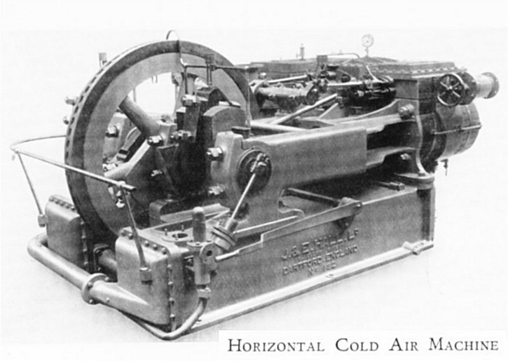 | Left: A J&E Hall horizontal cold-air machine: date?
|
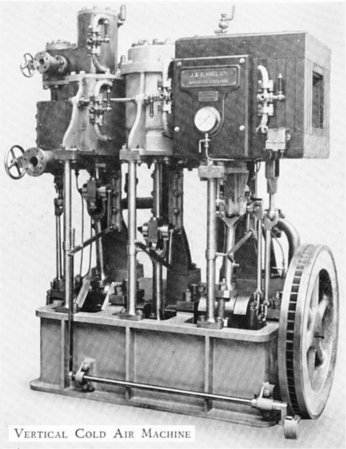 | Left: A J&E Hall vertical cold-air machine : 1886
|
THE HASLAM REFRIGERATING MACHINES: 1882
 | Left: Haslam refrigerating machine: 1882
|
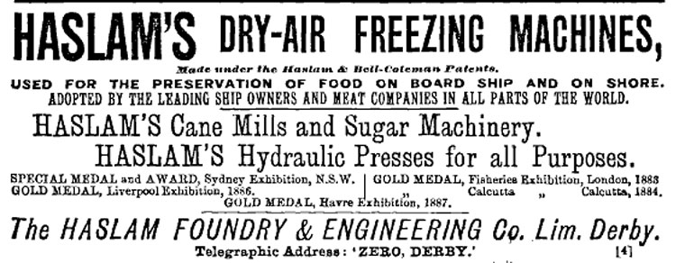 | Left: Haslam advert: 1891
|
 | Left: Haslam cold-air machine: 1880
|
 | Left: Haslam cold-air machine: 1880
|
 | Left: Haslam cold-air machine: 1880
|
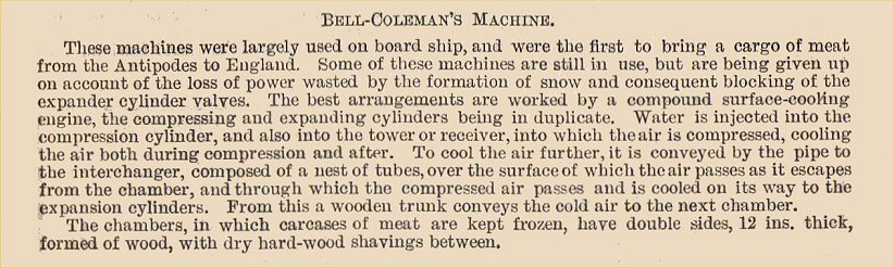
THE BELL-COLEMAN REFRIGERATING MACHINES
Bell and Coleman were one of the leading suppliers of air refrigrators.
"The Bell-Coleman refrigerator consists of an ordinary machine for producing cold air by compression, cooling, and expansion, combined with an apparatus for depositing a portion of the moisture before the air is admitted to the expansion cylinder.
In this system the air is partially cooled during compression by the actual injection of cooling water into the compressor, and by causing the current of compressed air flowing from the pumps to come in contact with a spray of water. From the pumps the mixed air and water is led by pipes into a chamber or chambers with perforated diaphragms, which catch a portion of the suspended moisture. The air, still in its compressed state, and cooled to within 5 or 10 degrees of the initial temperature of the cooling water, is then led to the expansion cylinder through a range of pipes, or other apparatus, with extended metallic surfaces, cooled externally to a lower temperature than that of the cooling water; so as to induce a further reduction in temperature and consequent deposition of moisture.
This extra cooling of the compressed air is effected either by allowing the cold expanded air, before it reaches the chamber to be cooled, to come in contact with the range of pipes, or by exposing these pipes to the spent air passing from the cold chamber. The author then considered at considerable length the objections to which the machine was open. It should howwever, be stated that he very frankly added that these machines have been successfully worked in cases where a large amount of cooling water of low temperature is available, as, for instance, on board an ordinary Atlantic steamer. There is no doubt that moderately dry air would be obtained wherever a sufficient supply of water at 46 deg. or 50 degF can be had."
 | Left: A Bell-Coleman air refrigeration machine: 1881
|
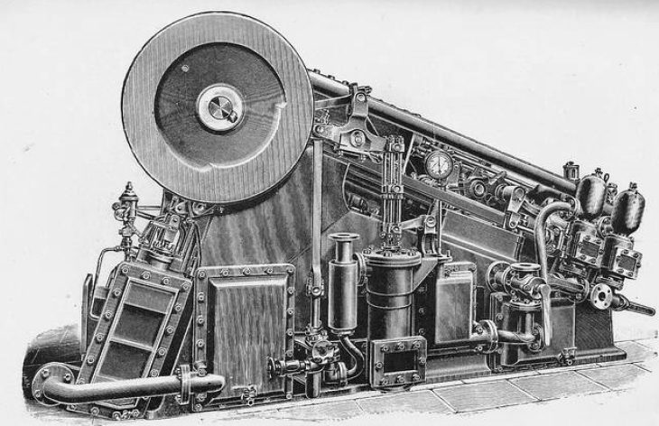
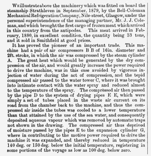
The first Bell-Coleman machine was used on the SS Strathleven, which brought the first successful cargo of frozen meat from Australia to London, arriving in February 1880. The machine illustrated above is described as "a new type of machine of small dimensions for the cooling of ships' provisions" rather than freezing the whole cargo.
 | Left: Bell-Coleman air refrigeration machines on ships: 1879
|
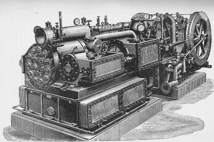
 | Left: Bell-Coleman air refrigeration machines on ships: 1881 article
|
 | Left: Bell-Coleman air refrigeration machine: 18??
|
 | Left: Notes on Bell-Coleman machine: 1903
|
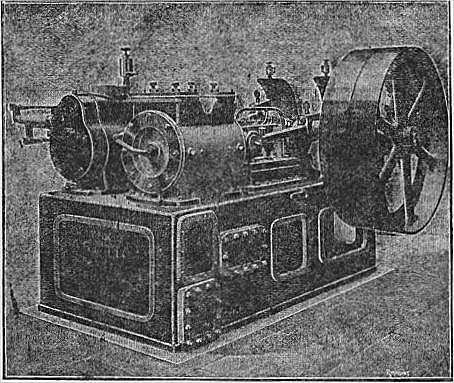
THE ALLEN DENSE AIR MACHINE
The splendidly-named Allen Dense Air Machine was a relatively late entry into the air refigeration market. Little is known about its operating parameter; I can only assume that 'Dense Air' refers to working at higher air pressures than usual to make the machinery more compact.
 | Left: Allen Dense Air refrigerating machine: 1883
|
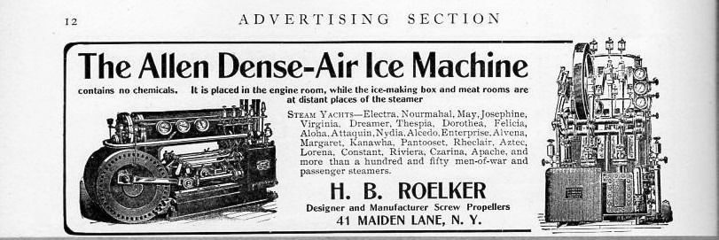 | Left: Allen Dense Air ice machine: 1883
|
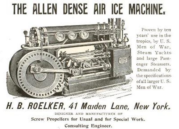 | Left: Allen Dense Air ice machine: 1883
|
THE LIGHTFOOT MACHINE
As we have seen above, Mr Lightfoot- full name Thomas Bell Lightfoot- was an employee of Messrs J & E Hall and Co, of Dartford in 1881, when he made the comments reported above. He was only with them for a short time; he then branched out on his own, working in London as a Consulting Engineer. At this time he designed and patented his own Dry Air Refrigerating Machine. A public company incorporated as Linde British Refrigeration Co had been formed in 1885, and in 1890 the company appointed Lightfoot as its Managing Director. The name was changed to Lightfoot Refrigeration Company in 1916. In 1922 the company still had its head office in Victoria Street, London.
 | Left: Lightfoot refrigerating machine: 1886
|
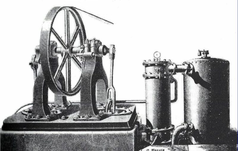
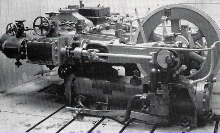
THE T & W COLE ARCTIC DRY AIR MACHINES: 1903
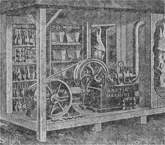
T & W Cole Ltd manufactured the 'Arctic' air refigerating system. Information on this company has proved very hard to find.
 | Left: Cole refrigerating machine: 1903
|
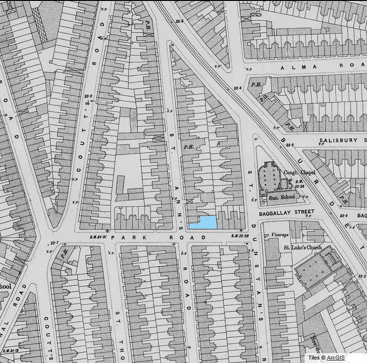 | Left: Part of Bow, East London: 1893-5 OS map series
|
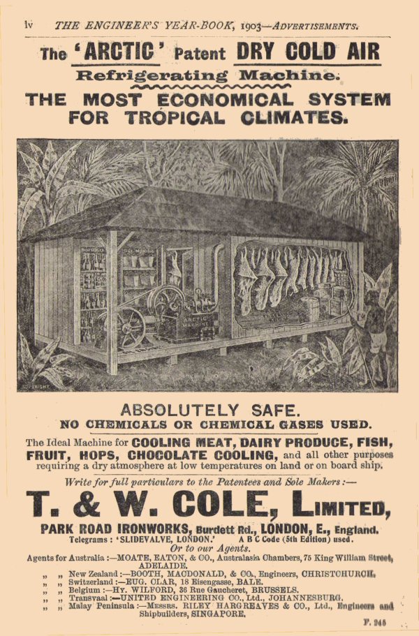 | Left: Advert for the Arctic system: 1903
|
 | Left: Cole refrigerating machine: 1903
|
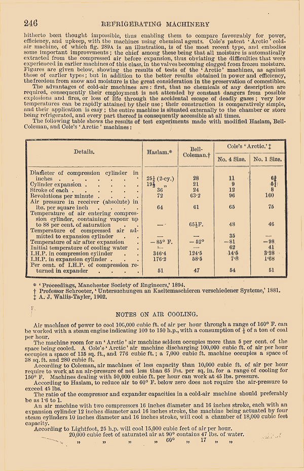 | Left: p246 of The Engineer's Year-Book: 1903
|
THE LINDE COLD AIR MACHINES
A public company incorporated as Linde British Refrigeration Co was formed in 1885, and in 1890 the company appointed Lightfoot as its Managing Director. The name was changed to Lightfoot Refrigeration Company in 1916. In 1922 the company still had its head office in Victoria Street, London.
 | Left: Linde refrigerating machine: 1891
|
Cold-air machines were largely displaced by ammonia machines during the 1880's.
![]()

|