M o n o w h e e l s: Page 2
|
| |
The story of vehicles with insufficient wheels.
THE GARAVAGLIA MONOWHEEL: 1904
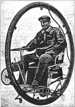 |
| This is the first motor-powered monowheel I know of.
Below is the original caption. Translated by your humble scribe, as best he can.
"PETROL MONOCYCLE."
"The picturesque machine shown below was shown at the Milan Exposition by the House of Garavaglia. It was, it appears, a genuine success.
The principle is easily understood by examining the figure. The big tyre with its rim fitted internally with ball-bearings, upon which the fixed frame sits, which supports both the driver of this strange vehicle, and the petrol engine; the rim of the tyre is moreover toothed on the side, and engages with the pinion of the engine; this can be seen at the bottom right of the picture. In sum, the mobile tyre rolls around the built fixed engine.
This arrangement is certainly amusing and jolly, but it is strange to note that this fantastic apparatus is however more perfect (in theory) than the ordinary motorcycle, since it implements direct command, without intermediaries uselessly absorbing power!"
It is however, much less perfect in practice. Note the suspicious-looking wheel out on the left. A stabiliser? Shouldn't there be one on each side?
From " La Vie de l'Automobile " for 23/04/1904 (n°134) p260.
|
THE EDISON-PUTON MONOWHEEL: 1910
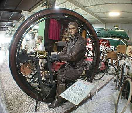 |
| Left: The Edison-Puton Monowheel: 1910
Stephen Ransom tells me this is a French monowheel built in Paris by Erich Edison-Puton in 1910. It has been restored by Ferdinand Schlenker of Sexau and is fully operational, being frequently demonstrated by Mr. Schlenker in the Museum carpark.The engine is a 150 cc single-cylinder De Dion giving 3.5 HP.
The machine is in the Auto & Technik Museum, at Sinsheim in Germany. Another very early motorised monowheel.
Picture and info courtesy of Stephen Ransom
|
THE COATES PROPELLOR MONOWHEEL
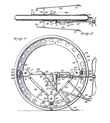 | |
The Coates Monowheel Patent: 1912
A brave attempt to add the difficulties of propellor-drive to the instabilities of the monowheel. But- it's not quite as daft as it appears; the use of a propellor means that the wheel is always pulled/pushed forwards, without relying on the weight of the rider and engine to provide reaction. There is therefore no possibility of gerbilling due to incautious acceleration; but it could still happen when you try to brake. One wonders if the inventor planned this as a practical street vehicle. It seems unlikely, as surely no one can have convinced themselves that pedestrians and propellors were a good combination.
This design used a pusher propellor, but otherwise bears a strong resemblance to the machine on the cover of Popular Mechanics. (See D'Harlingue below)
|
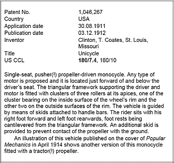 | |
The Coates Monowheel Patent: 1912
Note that steering is by hand-operated skids on each side, which is hardly elegant due to the frictional losses. Most monowheel inventors relied on leaning the wheel to steer.
Data and picture courtesy of Stephen Ransom.
|

AERIAL WHEEL SYNDICATE MONOPLANE: 1912
A propellor-driven monowheel is already a big challenge, or more like two of them. So why not go the whole way and build a flying monowheel?
And here is one. Regrettably (or more correctly, fortunately) no one attempted to fly it. It was a canard design, with the elevator in front of the aeroplane. This was not uncommon at the time, (it's what the Wright Brothers did) but was quite rapidly abandoned as it caused instability in pitch (if the plane tilts upward, the canard elevator becomes more effective and tilts it up more) and could lead to a stall from which it was impossible to recover. There was also no rudder, and no directional control at all; how where you supposed to steer it?
It was built by the Aerial Wheel Syndicate Ltd, led by Ralph Platts and George Sturgess, of Mablethorpe, Lincolnshire, to compete in the Military Trials in September 1912.
 | |
The Aerial Wheel Syndicate Monoplane: 1912
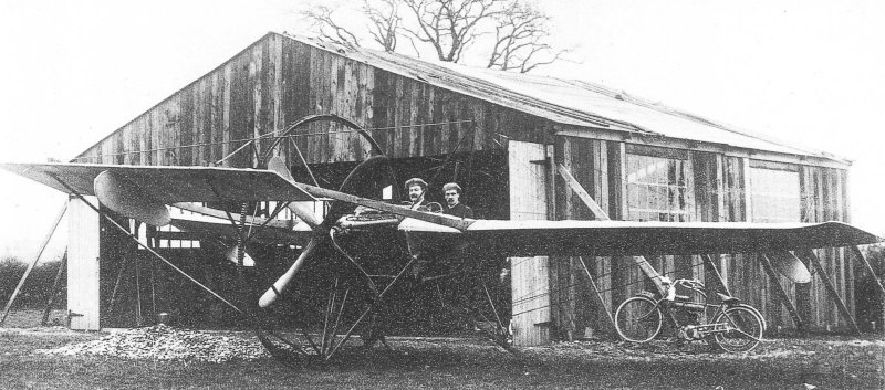
Note the four-bladed propellor, mounted at the front of a nacelle which housed the engine, and apparently two cramped seats for the crew. All of this is inside the big wheel. The original photograph appears to show that the outer rim of the wheel was covered with gear-teeth rather than a tyre. Possibly the wheel was driven by the engine.
The use of a big wheel was one of the sounder ideas embodied in this machine. Its large diameter would roll easily over the rough grass surfaces that aircraft operated from in those days, and facility in taking-off and landing from rough grass was a major War Office requirement.
Thanks to Paul Dunlop for bring this machine to my attention
|
From "British Aircraft before the Great War" by Michael Goodall and Albert Tagg (ISBN 978-0764312076), pp 9 & 10:
|
|
"This most unorthodox monoplane arrived incomplete at Larkhill for the Military Trials in September 1912 but although entered as No.18 it took no part in the trials. The machine, which was built in Birmingham, was a tractor canard with swept wings and was powered by a 50hp NEC four-cylinder, water-cooled, two-stroke engine. A nacelle between the booms that supported the front elevator housed both engine and crew and was surrounded by a circular frame incorporating a revolving tread which, with skids under the wings, constituted the landing gear. Patent No: 26 924/1908 was an early version by the Sturgess brothers."
"Pilots were reluctant to test the Aerial Wheel and it is believed that the machine was abandoned unflown. It was still in existence in a hangar at the Midland Flying School at Billesley Common, King's Heath, Birmingham when it was wrecked by a gale in the autumn of 1915."
|
|
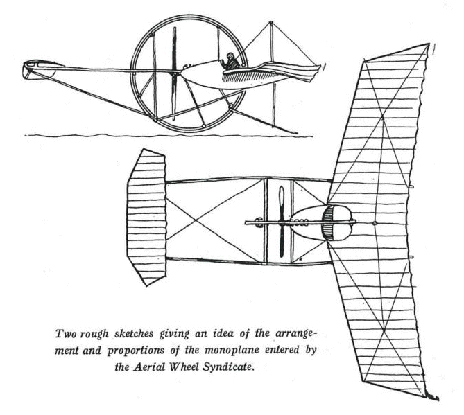 | |
The Aerial Wheel Syndicate Monoplane: 1912
Note the four-bladed propellor is inside the big wheel, and note the anti-gerbilling skids protruding at the rear.
There is a Wikipedia page, but very little else is available by Googling.
|

THE D'HARLINGUE PROPELLOR-DRIVEN MONOWHEEL: 1914-17
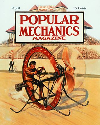 | |
The Cover of Popular Mechanics for April 1914
As if driving on one wheel did not present difficulties enough... this version adds propeller propulsion, apparently using a three-cylinder air-cooled radial engine.
When I first saw this picture, I naturally wondered if it was real or just a project. The comprehensive and business-like anti-gerbilling skids, and the counterweight/roller at the back to balance the forward position of the engine, did seem to indicate a practical design. On the other hand, the proportions of the propeller looked very wrong.
Note that the banner between the two towers calls it a "unicycle" and also indicates that the event is a time-trial; there was clearly no similiar machine to race against.
The alert reader will note that both Coates (above) and D'Harlingue lived in St Louis. At first it seemed likely that they were collaborators- however, see Letter 2 below.
|
Oh, it was real alright! I now have much more information on this remarkable machine, by courtesy of Mark D'Harlingue, the grandson of the inventor. The picture above is actually rather accurate, apart from that worrying propellor. I thought it might have been optimised for efficiency at low forward speeds, but it doesn't look much like the propellor in the two pictures below.
 | |
The Harlingue monowheel in April 1914
This photograph accompanied the Popular Mechanics article, and is very clearly the prototype for the cover painting above.
The proportions of the propellor look even more extreme in real life- it doesn't look anything like a standard aeroplane propellor, perhaps because it was expected to produce thrust at a lower forward speed. Note the caption calls it a 'tractor'.
The round thing at the rear is a roller- when stationary the machine rested on that and the side skids. Once it was moving the driver would lean forward to raise the roller from the ground.

Link to Popular Mechanics article kindly provided by Lars Cain.
|
According to the article, the machine had reached 67 mph 'on the boulevards of St Louis' though it is difficult to imagine anyone being daft enough to let this pedestrian-mincer run around on the public streets. The wheel is described as 81" in diameter, with a 2" solid tyre. The frame was located in the wheel by three 5" fibre rollers, 1" thick, with smaller slide rollers for horizontal location. The propellor was 5 feet in diameter with a 4-foot pitch, and a thrust of 150 pounds was claimed. No detail were given of the three-cylinder engine except that it used magneto ignition.
 | |
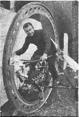
The D'Harlingue Monowheel with its inventor in 1917
Three years later, this looks like a conventional propellor rather than the strange broad-bladed affair pictured above. The prongs at the front are clearly intended to stop the propellor from striking the ground.
It appears that the whole engine and propeller assembly were swivelled for steering purposes. It doesn't appear to be a good way to get a small turning circle.
It's hard to be sure, but this looks like the same engine as the 1914 photograph; however now one cylinder is pointing upwards. This might mean that the engine has been re-installed, but I suspect the real answer is that it was a rotary engine, in which the cylinders go round with the propellor while the crankshaft stays still. They were popular at this time.
The machine looks a bit less tidy than in the picture above, where it may have been stripped down for photography. Here the driver has a wooden box at his feet. Judging by the wires attached it contains a battery for the engine ignition. Note that the side-skids have now been fitted with small wheels.
|
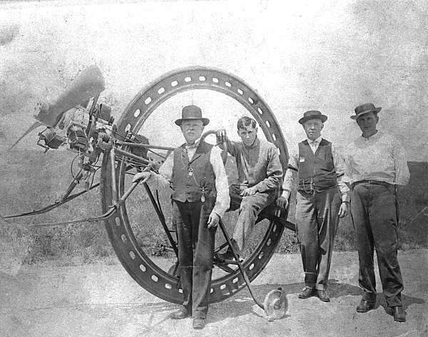 | |
The D'Harlingue Monowheel with a group of interested persons.
This photo was clearly taken at the same time as the one above. The background looks very much like some sort of painted backdrop.
The identities of the other three men are not currently known.
|
 | |
The D'Harlingue Monowheel
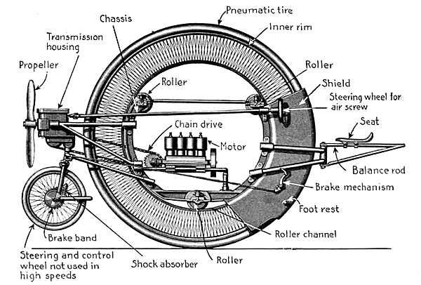
A diagram of a rather different version, clearly taken fom the D'Harlingue patent drawing below.
Note that the driver/pilot/rider now sits behind the wheel, rather than inside it, a unique approach to monowheel driving. Once again, "inclination of the body" is not relied on for steering. Here there are actually two steering mechanisms- the front wheel for low speeds, then swivelling the propellor at high speed. How well the latter worked I can only guess; very poorly, I suspect.
I want no quibbles as to whether this counts as a monowheel or not.
|
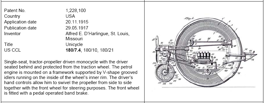 |
| Left: The D'Harlingue Monowheel patent drawing
Note that it was called a monocycle and not a monowheel. What is not clear is how the front wheel was raised and lowered, and what was done about braking when it was raised.
Data and picture courtesy of Stephen Ransom.
|
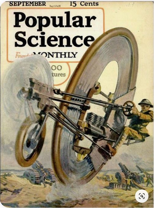 |
| Left: The Cover of Popular Science: 1917
A magnificent picture. Note the horrified look on the face of the unfortunate driver.
This was clearly taken from the patent drawing, having the seat at the rear and a forward wheel for low-speed steering. I can't believe that anyone would have thought this was a viable military vehicle- imagine trying to get it across the shell-torn wastes of World War One. Actually, the wheel seems to headed away from the enemy, assuming the big guns at the rear are firing at them, but on the other hand the driver may have had very little directional control. To be fair the picture claimed it showed a 'dispatch rider' and so would not be expected to charge at the enemy.
Nitpick- the engine here has three cylinders but there were four in the patent.
Source: Popular Science September, 1917. The article was called "Here's the Air-Propelled Unicycle." on p370
|
 |
| Left: The plot thickens...
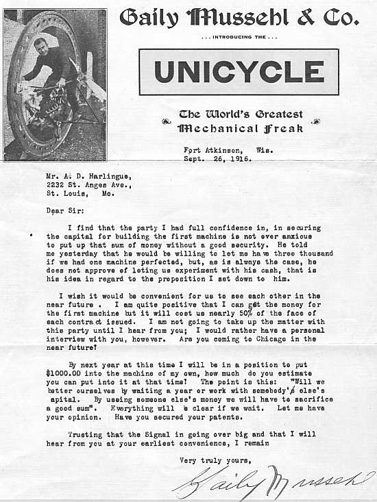
This picture comes from the letterhead of one Gaily Musselh. It appears at the top of a letter addressed to Alfred D'Harlingue, (see below) but has a two-bladed pusher propellor, (at first I thought it was 4-bladed, but I think it has a white fencepost behind it) and is a close approach to the Coates patent, apart from the size of the engine; it is clearly the machine depicted in "Our Own Oddities" below.
Picture courtesy of Mark D'Harlingue
|
 |
|
Left: Letter 1, from Gaily Musselh to Alfred D'Harlingue: 1916.
This is the letter from Gaily Musselh to Alfred D'Harlingue. Note that the monowheel is described as a "mechanical freak" which would seem to suggest that Mr Musselh does not think that the monowheel is the final answer to the world's transportation problems.
Letter courtesy of Mark D'Harlingue
|
 |
|
Left: Our Own Oddity.
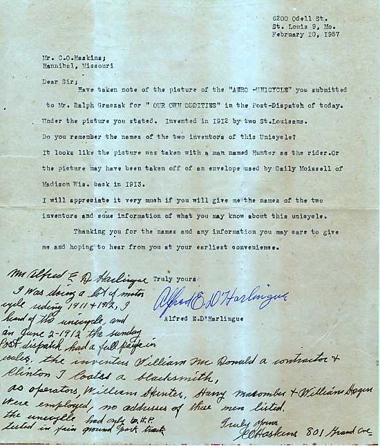
This looks more like the Coates monowheel above, but has features of the D'Harlingue patent, such as the big four-cylinder engine. It seems very likely that the "two St Louisans" mentioned here were Coates and a contractor called McDonald working in partnership. See Letter 2 below.
The picture appears to have published in 1957, when Alfred D'Harlingue was still alive. See the second letter below.
It might be remarked that the "theoretical speed" of 720 mph is only just below the speed of sound. (760 mph)
Picture courtesy of Mark D'Harlingue
|
 |
|
Left: Letter 2, from Alfred D'Harlingue to C O Haskins, with reply: 1957
This letter makes it clear that Alfred D'Harlingue was not in partnership with Coates, because he is enquiring about a monowheel that appears to be based on the Coates design. Mr Haskins states in his handwritten reply that the "two St Louisans" mentioned were a contractor called William McDonald and Clinton Coates, who is described as a blacksmith.
The reply gives the horsepower of the engine, but unfortunately it is not decipherable. it could be 6 , 10, or almost anything.
Letter courtesy of Mark D'Harlingue
|
The mystery is really how two monowheels that appear to have been developed separately come to have identical and distinctive wheels. I have counted the holes, and there looks to be the same number. I suspect that both wheels came from the same source; probably some sort of agricultural machinery.
THE GYRO-WHEEL
 |
|
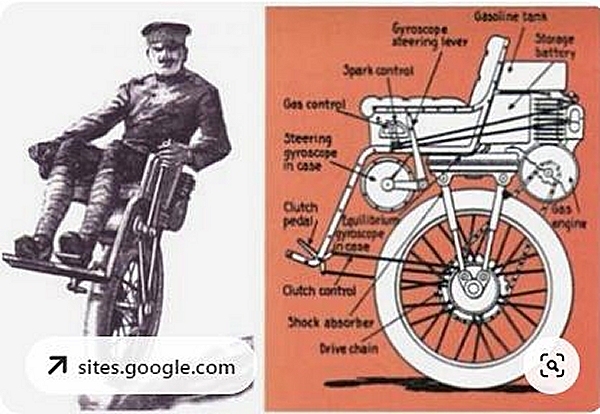
Left: Gyro-wheel: 1914?
This image shows a monowheel directed by not one but two gyroscopes. The one under the seat (hopefully) keeps the machine upright, while the other gives steering control. The puttees worn by the soldier suggest a time around World War One.
Intriguingly, the picture on the left looks like it might have been derived from a photograph, suggesting a prototype might have been built.
I hope this was not conceived as an assault vehicle; lurching across no-mans-land sitting upright is unlikely to have been attended with success.
All attempts to trace the source of this image have failed; can anyone help? The style suggests a magazine like Popular Mechanics.
|
THE GYRO-ELECTRIC DESTROYER: 1918
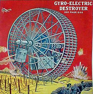 | |
The Gyro-Electric Destroyer on the Cover of "The Electrical Experimenter": Feb 1918
As a solution to the stalemate of trench warfare in the First World War this machine seems to lack any advantages. It might have crossed big shell-holes, but it would have been visible approaching for miles, and would no doubt have collapsed in an avalanche of high-explosive shells. Steering was to have been accomplished by shifting the central gyroscope wheel sideways.
Clearly an artist's fantasy rather than a serious project.
The Electrical Experimenter was an American publication.
|
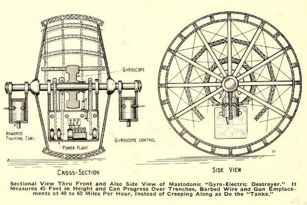 | |
Illustration of the The Gyro-Electric Destroyer: Feb 1918
I doubt if swinging about in the 'fighting cars' would be a pleasant or productive experience.
The article describing the The Gyro-Electric Destroyer appeared in the The Electrical Experimenter for Feb 1918, starting on page 666. I don't think we should read too much into that.
It was written by Hugo Gernsback.
|
THE VICTOR MONOWHEEL TRACTOR: 1918
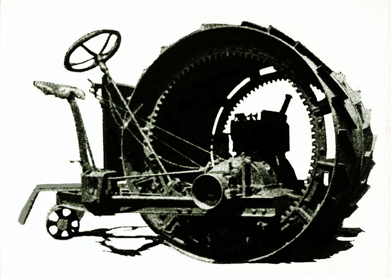 |
| The Victor monowheel tractor: 1918
Here the engine is inside the wheel, but not the driver.
This machine has now been identified as a Victor, made by the Victor Tractor Company in Minneapolis, Minnesota in 1918. It had a 4-cylinder Climax engine with 5x6-1/2 inch bore and stroke. The tractor weighed a hefty 4,500 lbs and sold for a hefty $1,685. The inventor, Victor Richard Hanson, took out US Patent 1,299,178 and Canadian Parent 201,172, the latter illustrating the production version. The tractor was not on the market for long.
My grateful thanks to Adolf Jaeger, who provided this information.
Drive to the wheel is via the two internally-toothed rings, and there is what looks like a power-takeoff (PTO) pulley this side, for driving other farm machinery. This actually looks like a rather practical idea.
It seems to be actually a diwheel, with the two wheels mounted right next to each other. That would explain why there are two internally-toothed rings rather than one. It would also explain how the thing was steered, by changing the relative speeds of the two wheels. The little wheel at the back seems to be just a stabiliser, and quite incapable of steering the machine.
There is a Wikipedia page for monowheel tractors, but there the term means having a power unit with a single conventional wheel; since it is connected to a two-wheel trailer it is essentially a tricycle.
|
There is more info here, where it is speculated that this is a part-constructed prototype because there is no sign of a radiator. No other photo appears to exist.
 |
| The Victor monowheel tractor US patent: 1919
This confirms that the tractor was indeed really a diwheel, but it's staying on this page for the time being. Steering was achieved by the two clutches labelled 19.
B is the engine, apparently a two-cylinder unit. 37 is the PTO pulley.
Source: USA patent 1,299,178 1 April 1919. The dating is perhaps a little unfortunate.
|
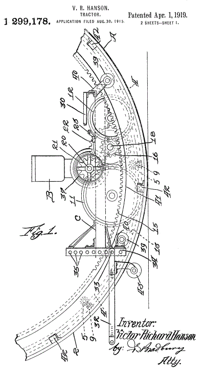 |
| The Victor monowheel tractor US patent: 1919
This shows how the engine B drove the two wheels via gear 16 meshing with the internal-toothed gear ring.
Source: USA patent 1,299,178 1 April 1919.
|
THE ICEWHEEL: 1925
 |
|
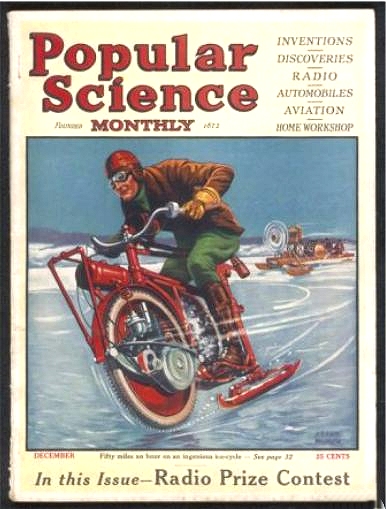
The Icewheel: 1925
Swiss-American Thomas Avoskan built this monowheel-plus-ski machine. On close examination the wheel is fitted with studs to give grip. The motive power is a Smith Motorwheel, identified by its horn-shaped brackets.
Note the propellor-driven sleigh in the background.
Source: Popular Science Monthly December 1925
|
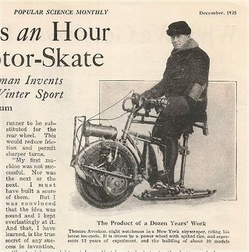 |
|
The Icewheel: 1925
A leather belt studded with half-inch steel spikes was fixed to the rubber tyre of the Motorwheel. The machine was steered by the handlebars, which were connected to the swivelling runner at the rear. Popular Mechanics claimed that it would go at 50 mph and ran 60 miles on a gallon of gasoline, and could tow a line of ten skaters.
Thomas Avoskan says in the article he built a score of prototypes over twelve years before achieving success, which reminds me of James Dyson saying it took him five years and 5,127 prototypes before he came up with his vacuum cleaner. It does not sound like well-directed research.
Source: Popular Science Monthly December 1925
|
 |
|
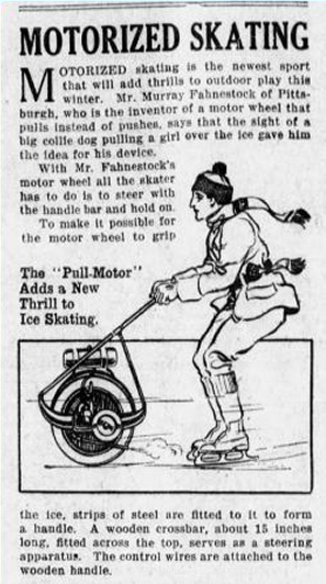
Motorised Skating: 1917
But hold on. Perhaps Mr Avoskan was not as original as he thought. This is clearly a skater being pulled along by a Smith Motorwheel. The inventor was a Mr Murray Fahnestock.
Mr Murray Fahnestock comes up on Google as the author of several books on the Model-T Ford; sounds like the right guy. No other details have so far been found.
The date of the article is believed to be 1917, but this has not so far been confirmed.
|
THE CISLAGHI MOTORUOTA: 1923
 |
|
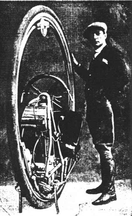
The Motoruota: approx 1927.
This may be Cislaghi standing beside his invention.
It would appear that Cislaghi was the founder of the Motoruota company; see more below.
"Motoruota" is Italian for "motorwheel"
|
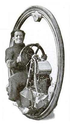 | | Davide Gislaghi awheel: 1924
This is indisputably Davide Gislaghi, the inventor, on/in one of his creations. Note there seems to be some differences of opinion about the spelling of his name. Gislaghi/Cislaghi was a motorcycle policeman in Milan, Italy. Popular Science Monthly reports that he won a bet by riding one of his monowheels from Milan to Rome and then running it in front of the National Stadium in Rome.
From Popular Science Monthly for December 1924.
|
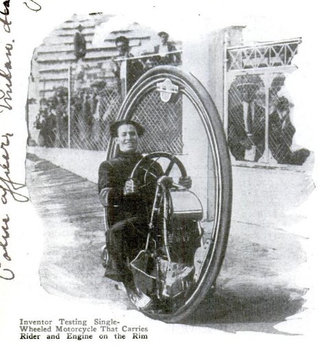 | | Davide Gislaghi awheel: 1924
This is a better version of the picture above. Judging by the writing at left, which says "police officer milano" the photograph was taken in Milan, Cislaghi's home town.
From Popular Science Monthly for December 1924.
|
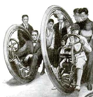 | | Two Motoruotas: 1924
Proof positive that at least two Motoruotas were built. Different frame and wheel sizes were an option.
From Popular Science Monthly for December 1924.
|
 | | Oh no it isn't!
The Garavaglia monowheel was at least 20 years earlier.
|
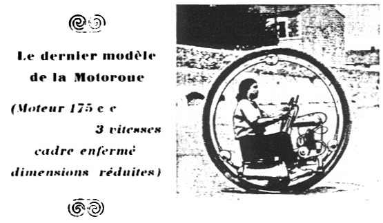 | | The latest model
The original caption reads: "The Latest Model of Motorwheel.
(175cc engine, three gears, frame reinforced, size reduced)
This was clearly another brave attempt to commercialise the monowheel.
|
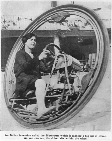 |
| This picture appeared in "Motorcycling" magazine for July 20, 1927. No further details were given.
Picture kindly supplied by Cindy.
|
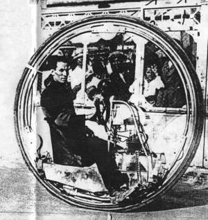 |
| This looks like another Motoruota. No further details available.
Picture courtesy Stan Smith
|
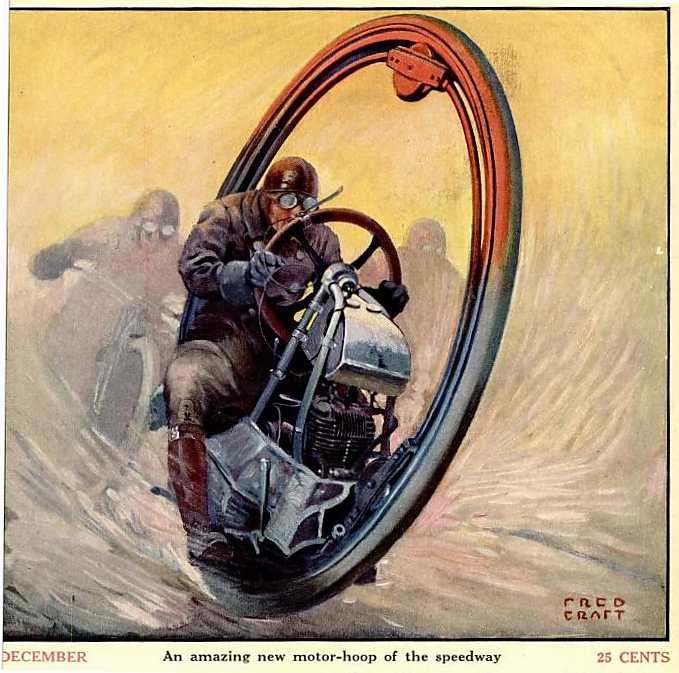 |
| A Motoruota monowheel: 1924
Superbly rendered on the cover of Popular Science Monthly for December 1924.
|
 | |
Diagram from Cislaghi's French patent, No 573,801. 1924.
This shows how the wheel was tilted with respect to the inner frame.
Picture kindly provided by Stephen Ransom.
|
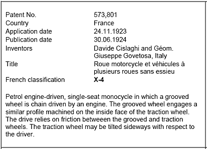 | |
Information on Cislaghi's French patent, No 573,801. 1924.
It is now pretty clear that Cislaghi was behind the Motoruota enterprise. (see below)
Data kindly provided by Stephen Ransom.
|
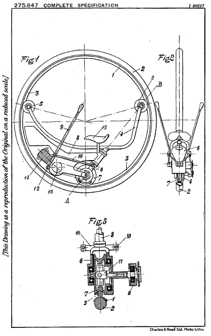 | |
Diagram from Cislaghi's British patent, No 275647. 1927.
Picture kindly provided by Patrick Appleyard.
|
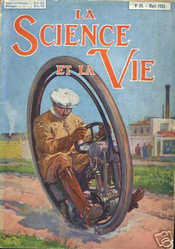 |
| The Cover of "La Science et la Vie" N°69 - Mar 1923
While it is unconfirmed, this cover painting appears probably of the Cislaghi machine, given the date of 1923.
The table of contents describes it as "Un curieux monocycle automobile".
|
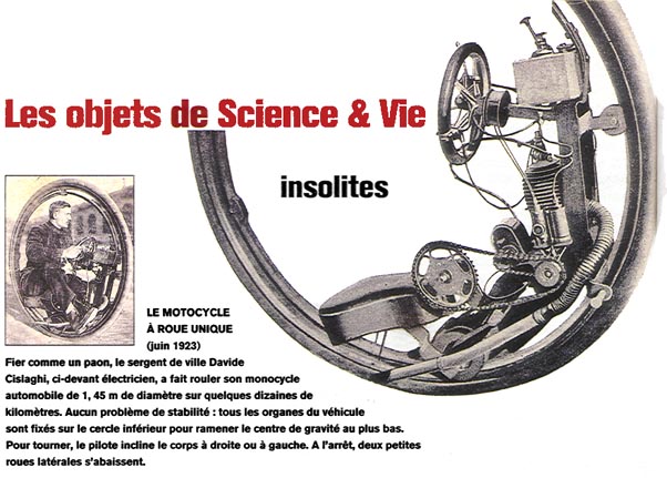 | |
From "Science et Vie" May 1993, p170
The text in the picture reads:
"Insolites" means "Strange"
"The motorcycle with one wheel. (June 1923)"
"Proud as a peacock, town sergeant Davide Cislaghi, a former electrician, has driven his 1.45 metre diameter monocycle for some dozens of kilometers. No problem with stability; all the vehicle parts are fixed to the interior circle to lower the centre of gravity. To turn, the pilot leans his body to right or left. On stopping, two little lateral wheels lower themselves."
|
There is a short Hungarian video of the Motoruota being demonstrated in Paris in 1932. Scroll down a bit.
A NEW TERROR: THE CHRISTIE MONOWHEEL of 1923
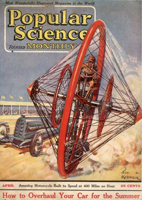 |
| Left: The Christie monowheel concept on the cover of "Popular Science Monthly" for April 1923.
This is an artist's impression of an invention by a Professor E.J. Christie of Marion, Ohio. It was certainly built- but most certainly wouldn't have reached 400 mph. To be fair, the inventor only claimed "a speed of at least 250 miles per hour, and possibly 400 miles per hour" though this is the sort of uncertainty that suggests he hadn't a clue what he was about.
There seems to be no reason to think that 250 bhp would have been enough to reach 250 mph (and lots of reasons not to try it) because the wind resistance of all those spokes and extra wheels would have been significant.
The design had a centre wheel of 14-foot in diameter, and weighed 2400 pounds. The "gyro wheels" on each side of the driver weighed some 500 pounds each.
The machine, which was reportedly "being constructed in Philadelphia" at the time, was to have been powered by a 250-horsepower airplane motor.
Brought to my attention by Harry Doughty, who rightly describes it as "the Mother of all monowheels!".
|
Here is the text of the Popular Science Monthly article:
"Will Gyroscopic Wheel Shatter Speed Records?
DOWN the track of a motor speedway a wheel 14 feet high whirls at such a dizzy speed that racing automobiles traveling at top speed of 115 miles an hour seem almost to stand still. So fast does the giant wheel travel that the details of its design can scarcely be distinguished. This is a possibility prophesied by Prof. E. J. Christie, of Marion, Ohio, for an amazing gyroscopic unicycle of his invention, now being constructed in Philadelphia, Pa. The 2400-pound 14-foot model of the speed wheel is almost ready for a trial spin and Christie confidently predicts that it will develop a speed of at least 250, and possibly 400 miles an hour!
In design, the strange vehicle resembles a giant bicycle wheel with an exceptionally long hub, at the end of which supporting spokes are fastened. Attached to the axle, on each side of the center are 500-pound gyroscopes designed to rotate at a speed of 90 revolutions a minute, a speed sufficient to maintain equilibrium.
Suspended from the axle by a frame, the upper end of which supports the driver’s seat, is a 250-horsepower airplane motor, the power of which is transmitted to the axle through a friction clutch, three-speed transmission, and jackshaft. An additional chain drive in the center of the axle connects the engine transmission with the gyroscopes.
The machine is controlled and operated like an automobile from the operator’s seat immediately above the axle. Here the driver is saved from swinging about the axle by the steadying weight of the engine slung below.
“How can such a strange vehicle be turned?” you may ask.
This problem Professor Christie has solved in a unique way. By means of the steering wheel, he shifts the position of the two gyroscopic flywheels on the axle to the right or to the left. When the center of equilibrium is thus shifted, the unicyle immediately turns in its course, without tilting, the degree of turn depending upon the distance the gyroscopes are shifted. In other words, the farther the shift, the shorter the turn.
The wheel is supplied with a seven-inch rubber tire, the manufacture of which proved a problem in itself. Pressure resistance was found to be so great that several attempts were made before a strong enough tire was produced.
The new gyroscopic unicycle is not the first machine of its kind Professor Christie has produced, although it is by far the most pretentious. He first used a gyroscope to demonstrate the rotation and momentum of the earth."
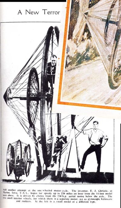 |
| Left: Oh no! He really did build it!
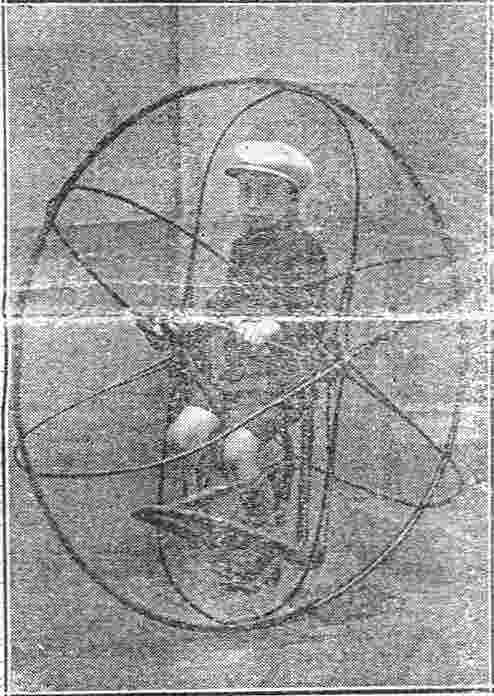
A day after I composed the above, Harry Doughty sent me this partial page from "Everyday Science & Radio News" for Feb 1923. It appears to be a poorly retouched photograph, the chap on the lower right looking rather like a cartoon. He certainly seems to be suffering from hip trouble.
In case the caption of this image is not readable, it says:
"Still another attempt at the one wheeled motor cycle. The inventor, E J Christie of Marion, Iowa, USA, hopes for speeds up to 250 mph from the 14-foot model seen above. It is driven by chains from the 250 hp aerial motor below the axle. The two small interior wheels, for which there is a separate motor, act as gyroscopic balancers and rudders. At the left there is a small model of a different type."
Some interesting points here. Clearly the editor was bored by monowheels, which seems to indicate they were already discredited as practical transport. Christie has not anticipated Kerry Mclean in fitting "rudders", ie aerodynamic surfaces; this appears to be a misinterpretation of the steering function of the gyroscope wheels.
A most interesting question is what happened if you stopped at a red light. Presumably it fell over sideways- and how would you get going again?
The small machine bottom left is rather a puzzle. It consists of no less than five wheels- but only one actually touches the road. It is too small for anyone to get inside and was presumably some sort of test model.
|
 |
|
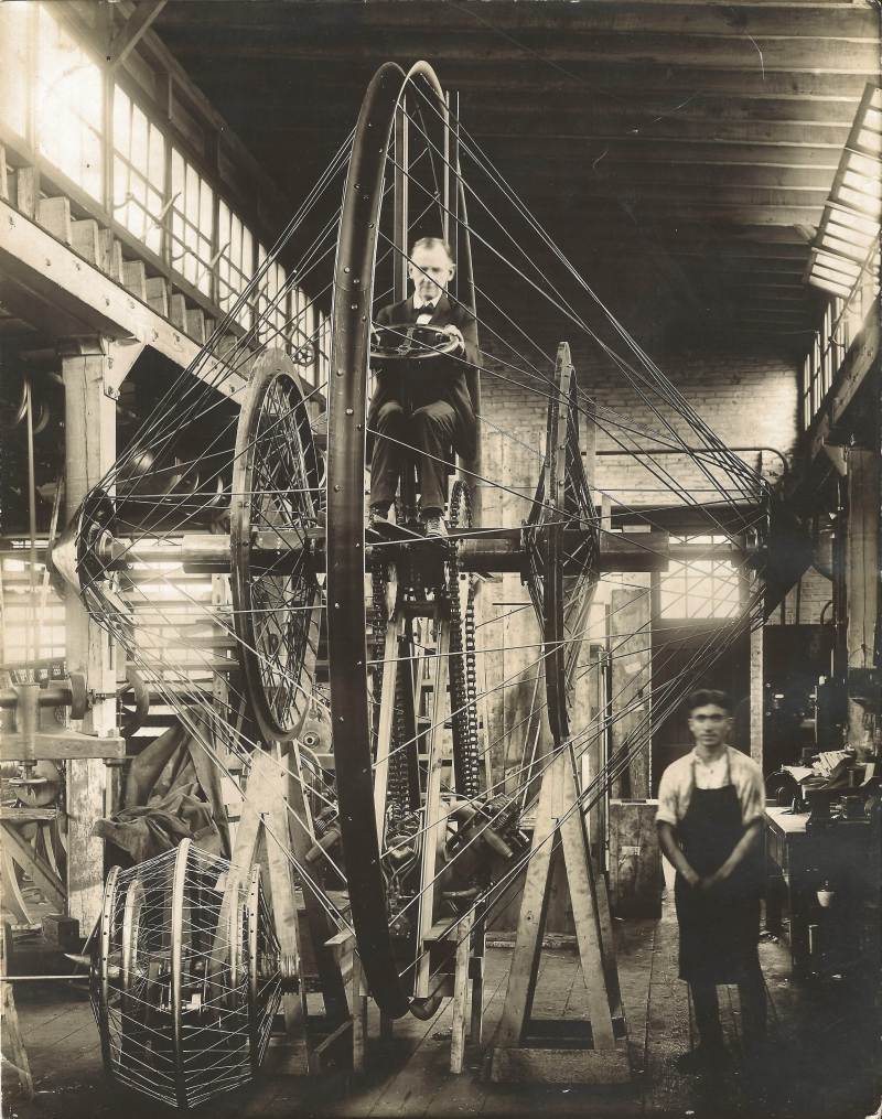
Above: The Christie monowheel under construction: 1923
|
This photograph was clearly taken at the same time as the one from which the rather poor image above was derived. The twin chain drive can be clearly seen. The engine is a V8 with stub exhausts. I can see no sign of either the "separate motor" or the separate chain drive for the inner gyroscope wheels as referred to above. Close inspection of the small machine to the left shows that it contains gears and possibly some sort of crank mechanism, but no engine is visible.
This magnificent picture was kindly provided by Sean Donley/3c salvage
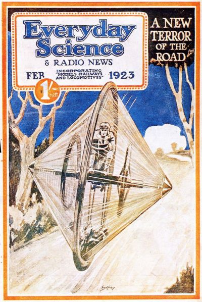 |
| Left: The cover of "Everyday Science & Radio News" for Feb 1923
They seem a mite unenthusiastic, but it is hard to argue with their headline. A New Terror indeed.
I am not qualified to judge whether or not the gyroscope steering system described above could have worked, but I have my doubts. No other monowheel designer seems to have found gyroscopes necessary for steering.
The final question is: was this machine ever actually run? The big photograph above seems to show a completed machine, apart from the absence of the tyre. Popular Science Monthly describes it as "almost ready for a trial spin" but in the inventing business "almost" can be a long way from completion. My suspicion is that it was never trialled, (possibly owing to a sudden attack of common sense on the part of Professor Christie) and if it had been things would have ended disastrously. Google is silent on the matter.
|
THE GYROCYCLE: 1926
 | | From " Dimanche Illustré " for 25/07/1926 n°178.
Original caption:
"A STRANGE VEHICLE: THE GYROCYCLE.
A Parisian inventor, M. Trual, amused himself by constructing for his son, this apparatus with one wheel. The cyclist is in equilibrium. The pedalling system, with ordinary gearing, permits 15 km/hour to be attained."
Jackie Chabanais says "It is very bizarre, but this child who was about 10 years old on the photo, I met him some years ago. He was very moved by seeing me in my tractowheel and he sent this photocopy."
|
BOY-SIZED MONOWHEEL
 |
| 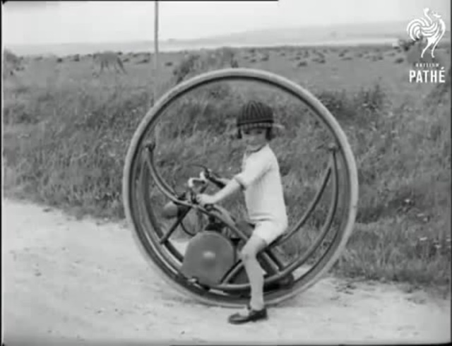 |
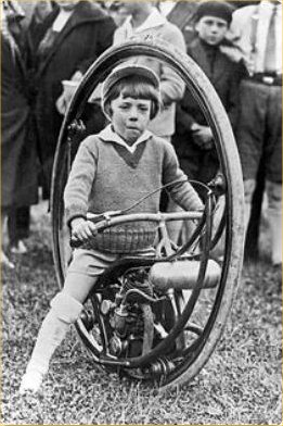
| Boy-sized Monowheel: 1927
This boy-sized monowheel was constructed, presumably by a proud father, in 1927.
There is a British Pathe video of the young lad in motion here, and the full version can be seen on YouTube. Dad has to run quite fast to keep up with the young shaver; in a sign of the times, the lad has to navigate through clumps of horse-droppings.
|
A FRENCH MONOWHEEL: 1927
 |
|
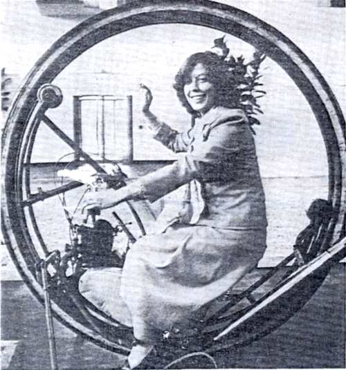
A French Monowheel: 1927
This picture comes from an unidentified German newspaper dated 16 June 1978. The caption reads: "No shortage of curiosities at the 'Old-Timer Exhibition' in Dusseldorf, where about 100 vehicles can be seen. Here is a French 'Mono Cycle' from 1927, which ‘put-puts’ along the roads at a maximum speed of 10 km/h."
Well, 6 mph should be safe enough. As we have seen, many monowheel builders were claiming quite unbelievable speeds.
Picture courtesy Stephen Ransom and Martin Frauenheim.
|
MR GERDE'S MOTORWHEEL
 | | Swiss engineer Mr. Gerdes astride/inside his one-wheel motorcycle at Arles, France, in 1931.
He was apparently on a journey to Spain- I have no info on whether he got there. At any rate, he looks cheerful enough here. I have always assumed that this machine was Gerde's invention, but it now looks as though he may simply have been one of the customers- and there were probably not that many- of the Motorouta company, described above.
|


