Here we deal not with motorbikes as such, but motorised bicycles, which typically have a small engine (very often a later addition) driving the front or rear wheel of a more-or-less standard bicycle frame. Motorwheels, (also called cyclemotors) which often used 2-Stroke engines, were notoriously unreliable. Basic servicing was sometimes required even if they were left unused for only a few weeks.
The engines, often only 35cc or less, had little power and on even a gentle hill you would have to resort to a bit of LPA. LPA (Light Pedal Assistance) was a discreet way to refer to the need to do quite a lot of pedalling. A major problem was that it was very difficult to incorporate a gearbox, so often the engine would be running at non-optimal rpm.
Engines were applied to either the front or rear wheels. Putting the engine on the front wheel, often just in front of the handebars, made the steering heavy, but it did mean all the engine controls were right to hand. But... most of the weight of a bicycle and rider is on the rear wheel, so you might expect much better traction. Despite this, there were many designs with front-wheel drive, the VeloSolex being the best-known example.
Ignition was (always, as far as I can tell at present) by magneto, so there was no need to carry a battery. It was usually a flywheel magneto to save space.
Many (all?) of these engines had a device called an exhaust valve lifter or decompressor; which may sound obscure today. It was a control on the handlebars that opened the exhaust valve via a cable no matter what the position of the exhaust cam. This prevented any compression in the engine to make push starting the engine easier, because there was no clutch to disengage. It could also also be used to rather crudely reduce engine power to slow down. To stop you had to keep the lever open until the engine stalled. To someone used to a clutch this all sounds rather unsatisfactory.
A two-stroke engine does not usually have an exhaust (or inlet) valve, so a separate valve just for decompression was fitted.
There is also the question of transmitting the engine power to the wheel. This might be by gearing, (eg Smith Motorwheel) by chains, (eg BSA Winged Wheel) or by friction roller onto the tyre. This might be one roller bearing down from above, or two rollers gripping either side of the tyre. The obvious snag is that the tyre will carry up water and mud from the road and compromise the friction drive. The machines with a roller on top of the wheel often had a lever that lifted the roller and gave the effect of a clutch.

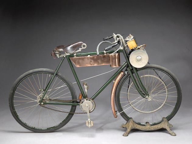 |
| Left: The Werner Motocyclette: 1898
This is really a motorbike rather than a motorised bicycle, even though it looks like the latter. It had a 198cc engine, much larger than those used later in motorwheels; this probably reflects the immature engine technology of the time.
Paris-based Michel and Eugene Werner had built their first motorcycle in 1896 by the simple expedient of mounting a single-cylinder petrol engine, designed by Hippolyte Labitte, in front of the steering head of a bicycle, directly above the front wheel, which it drove via a belt. Belts in this sort of situation are notorious for slipping.
It is famous as one of the first practical motorcycles, and proved an immediate success. The Werner brothers abandoned their existing cinematograph business to set up a factory to build it. Notorious entrepreneur Harry J Lawson, owner of the Motor Manufacturing Company (MMC), acquired the British rights to the design, which was built at his Motor Mills plant in Coventry. In 1900 Werner sold a staggering 1,000 units but by this time Lawson had found it more expedient to have the French factory supply him with complete machines.
|
 |
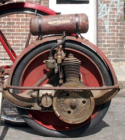
| Left: The Smith motorwheel: 1910
This is the only configuration so far known where you didn't just add an engine- you got an extra wheel as well. There would seem to be an obvious snag in that the weight at the rear of the bicycle was now split between two wheels, which I would have thought made the traction uncertain. However, the Smith motorwheel was popular.
The Smith Motor Wheel was an ingenious design. The disc wheel was driven directly from the cam-shaft, which was geared down 1:8 from the crankshaft to give a suitable drive ratio. However it was a 4-stroke engine and the camshaft of a 4-stroke engine must rotate at half engine-speed; Smith got round this by having four lobes rather than one on the camshaft, so it was effectively turning at half engine-speed.
This ingenious idea was borrowed from the Wall Motor Wheel, invented in England in 1910, of which Smith had bought the US manufacturing rights. The Wall Motor Wheel used a 4:1 reduction ratio and a two-lobed exhaust cam; the inlet valve was automatic.
|
 |
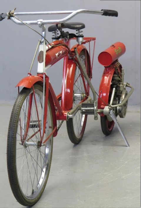
| Left: The Smith motorwheel: 1910
This is a different and unrestored example, believed to date from 1918. The bar in front of the flywheel looks as if it was a (not very effective) safety guard for the flywheel rather than a structural member.
There is much more information on the Smith motorwheel in the N-wheeled car gallery of the Museum.
|
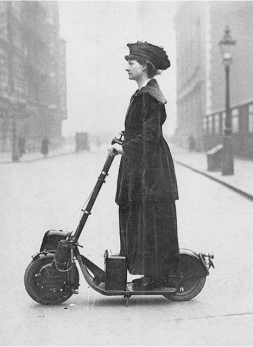 |
| Left: The Auto-Ped: 1916
This was the caption when the picture was originally published:
"Lady Florence Norman, a suffragette, on her motor-scooter in 1916, travelling to work at offices in London where she was a supervisor. The scooter was a birthday present from her husband, the journalist and Liberal politician Sir Henry Norman."
Not perhaqps a motorised bicycle, but the front-wheel drive intrigues me.
|
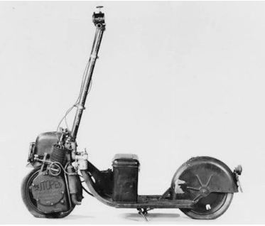 |
| Left: The Auto-Ped: 1916
A contemporary description:
"The engine is geared to the front wheel via a disk clutch. The flywheel, on the right side of the front wheel, contains a 6-volt lighting generator that originally furnished current for lighting and ignition, but the system later was altered by the addition of an ignition coil and four dry-cell batteries. The ignition switch is mounted on the right side of the frame, and the gasoline tank is above the front fender.
All control of the vehicle is through the steering column. Turning the column steers the machine in the conventional manner; pushing it forward engages the clutch; and pulling it back operates the internal, expanding brake on the front wheel. Turning the left grip operates the throttle, and turning the right grip operates the compression release through a wire controlling the opening and closing of the intake valve. A hand Klaxon is mounted on the left grip."
I am a little uneasy about declutching by pushing the steering column forwards.
|
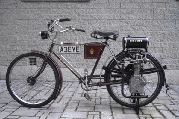 |
| Left: Merkel Motorwheel: 1916
Joe Merkel was born in Manistee, Michigan, in 1872. He designed the Merkel Motor Wheel, unveiled at the Cycle Trades Association convention in Atlantic City, 1916. The wheel was sold as a conversion kit for $80.
The Motor Wheel was a four stroke, over head valve unit with 2.5-inch bore and stroke, with a displacement of 200cc. There were two stages of drive reduction; the camshaft was geared down to turn at quarter crankshaft speed; normally the camshaft of a 4-stroke turns at half crankshaft speed, and so it had two lobes for each valve, on the same principle as the Smith Flyer. A gear on the end of the camshaft drove the wheel. The overhung crankshaft extended right through the wheel hub, to carry a flywheel magneto on the other side of the wheel.
There is more information here.
|
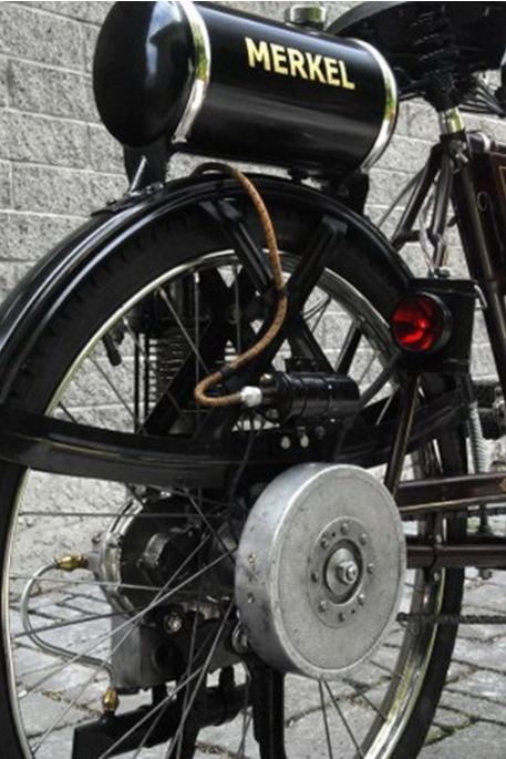 |
| Left: Merkel Motorwheel: 1916
This view shows the flywheel and above it an ignition coil- it appears that unlike most motorwheels it did not use a magneto? I know this contradicts the info just above. Further research indicated.
There is a mysterious metal pipe at bottom running from the crankcase to near the end of the exhaust pipe. Crankcase ventilation?
|
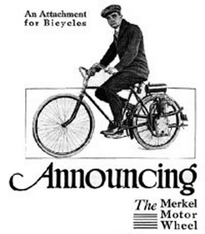 |
| Left: Advert for Merkel Motorwheel: 1916
|
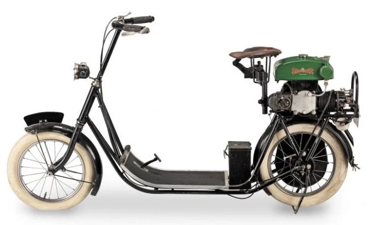 |
| Left: The ABC Skootamota: 1919
I know this isn't a cyclemotor per se, but it certainly looks like one.
The ABC Skootamota was designed Granville Bradshaw, a man with a reputation for wayward inventions like the Omega toroidal engine. There were earlier designs for aircraft engines and so on that failed to reach expectations. However, it appears that Mr Bradshaw got it right this time, and the Skootamota was very successful. One reason was its flat floor, which allowed ladies to ride it in the costume of the period ie skirts or dresses.
The single-cylinder four-stroke engine had a capacity of 123cc (60x44 mm) and deveoped 1.5 HP; it drove the rear wheel via the camshaft (for the 1:2 reduction ratio) and then a chain in a case running in an oil-bath; ther was no gearbox and apparently no clutch. The Amac carburettor was gravity fed from the fuel tank above it. Early engines were exhaust-over-intake but later versions had two valves. It was fitted with 16x2 3/8in. Clincher tyres.
There is more information here.
|
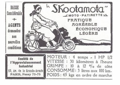 |
| Left: French ad for the ABC Skootamota: 1919
The Skootamota was manufactured and sold by Gilbert Campling Ltd of under a license from Mr Bradshaw. It was sold in Britain and throughout Europe.
From the ad we learn that maximum speed was 30 km/hr (18 mph) and was allegedly capable of climbing a 1 in 10 hill. There was of course no way to add pedal assistance, as on true cyclemotor machines.
The Skootamota is considered the fore-runner of all motor-scooters. It was so successful that it inspired a huge number of copycat competing machines, and the competition was so fierce that production only ran from 1919 to 1922. It is an unfair world.
There is more information here.
|
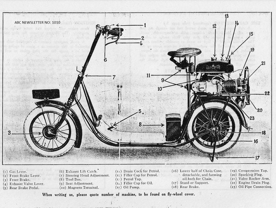 |
| Left: The ABC Skootamota: 1919
"THE A.B.C. Skootamota is the only exhibit at this stand. Two commercial types are shown, haying a box for parcels fitted in place of the usual seat. A spring saddle being attached direct to the top of this. A tropical model is also shown, enamelled in light colours, and fitted with a canopy. Three standard models are exhibited, one of which is nickel-plated all over. As is well known, this scooter is fitted with a small four-stroke engine of 124 c.c. The cylinder is placed horizontally over the back wheel, and is fitted with a detachable head, while the transmission is direct by chain to the back wheel. The valves are both located in the head, the inlet valve being at the side and the exhaust valve overhead. The power is transmitted through the camshaft, which allows of a sufficiently low gear being obtained without the use of sprockets of undue size, the wheels being 16 ins. by 2� ins."
Source of text: Motor Cycling 26 November 1919. Article on the 1919 Olympia show
The picture shows an exhaust valve lifting lever, and there is no mention of a clutch.
There is more information here.
|
 |
| Left: The ABC Skootamota: 1919
The other side of the Skootamota; the bottom of the chain-case is missing.
"Designed by Mr. Granville Bradshaw, the Skootamota is full of ingenious points. It is interesting to note that its cylinder forms half the unit of the neat little flat-twin stationary engine which Mr. Bradshaw designed for electrical generating sets and blowers for filling airships during the war. Following the original A.B.C. practice, the exhaust valve is situated in the cylinder head, which is detachable, and the inlet valve beneath it, while the cylinder is of steel, and is turned from the solid. One of the features of the Skootamota is that it is built as a miniature motor bicycle. The power unit is extremely neatly designed, and the transmission to the rear wheel is by a protected chain. The designer did not intend that the scooterist should stand, and the Skootamota is equipped with a comfortable pan seat. A novelty on this stand is a Skootamota equipped as a miniature tradesman's carrier, bearing the name of Messrs. Harrods, Ltd., and in this capacity it is possible that these little vehicles may prove to be extremely handy for the delivery of small parcels. Another scooter carrier shown is built for Messrs. Morel Bros. One Skootamota has a plated finish, and yet another is provided with a canopy for use in tropical countries."
Source of text: The MotorCycle 27th November 1919. Article on the 1919 Olympia show
|
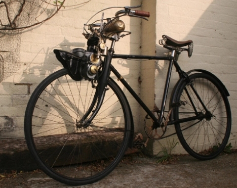 |
| Left: Motorised bike using a Labinal engine: 1922
The Labinal company manufactured auxiliary motors in Paris, for attachment to bicycles. The first Labinal Micromoteurs appeared in 1922; production ended in 1928. The 2-stroke engines had a capacity from 38cc to 50cc; one version (it is not clear which) gave 0.75 HP at 3500rpm. Drive was by a roller onto the front tyre.
There is more information here.
|
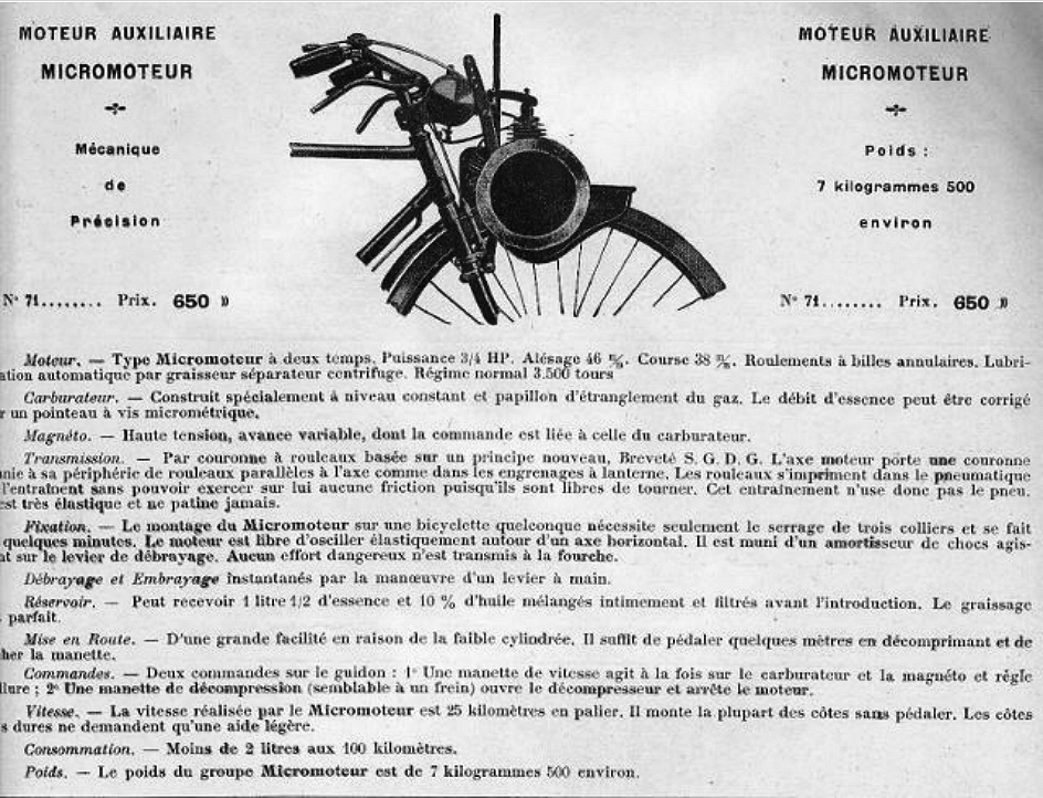 |
| Left: Technical details of the Labinal micromoteur: 1922
A good deal of information here. I plan a translation but for the moment you will have to use Google Translate.
|
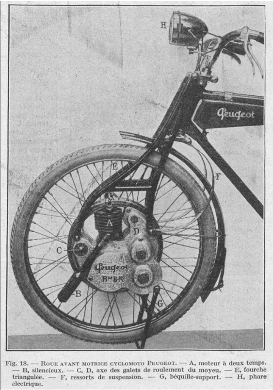 |
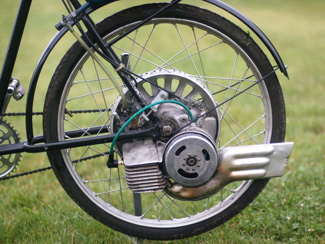
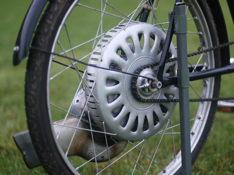
| Left: The Peugeot Motocyclo: 1922
Another of the rare machines with the motor fitted on the axle of the front wheel.
|
 |
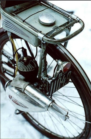
| Left: The Fichtel & Sachs Saxonette: 1938
The Fichtel & Sachs Saxonette motorwheel appeared in Germany in 1938; it was considered an improvement on previous designs and is regarded as the forerunner of the post-WW2 motorwheels, but had its problems and production ceased in 1939. It had a relatively large 60cc 2-stroke engine with a flywheel magneto.
After the end of WW2 engineers at DKW copied and improved the Saxonette to create the Radmeister project; this was a starting point the for British Cyclemaster engine.
|
 |
| Left: The Fichtel & Sachs Saxonette: 1938
The Fichtel & Sachs Saxonette motorwheel appeared in Germany in 1938; it was considered an improvement on previous designs and is regarded as the forerunner of the post-WW2 motorwheels, but had its problems and production ceased in 1939. It had a relatively large 60cc 2-stroke engine.
After the end of WW2 engineers at DKW copied and improved the Saxonette to create the Radmeister project; this was a starting point the for British Cyclemaster engine.
|
 |
| Left: Velosolex bicycle/moped: 1946
The French Solex company were a major manufacturer of carburettors; they also made the Velosolex machines. The engine is an integral part of the bike. The engine installation is very neat. They were extremely popular in France, and in total 8 million were sold in Europe. The Solex brand is now owned by Magneti Marelli.
|
 |
| Left: Velosolex bicycle/moped: 1946
The V�losolex used a 49 cc motor mounted above the front wheel. Drive a small ceramic roller that rests on the tyre. The first prototype VeloSolex was built in 1941, presumably intended as a response to petrol shortages in France during WW2. The motor was applied to standard bicycles such as the �Alcyon� brand, being initially by a 45 cc engine developed by Solex. VELOSOLEX were produced commercially from 1946 with a 45 cc engine without clutch, then later with a 49 cc engine.
There is more information here.
|
 |
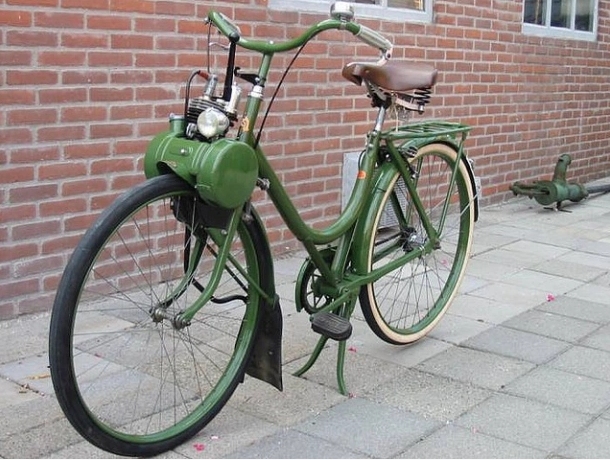
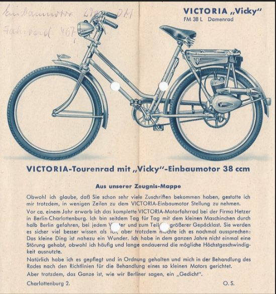
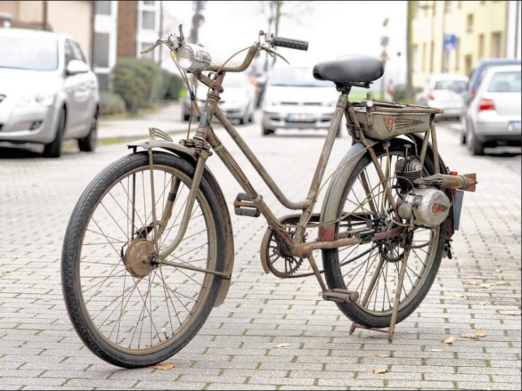
| Left: Victoria FM38 motorwheel: 1946
The 38cc Victoria FM 38 cycle-attachment engine (�hilfsmotor� in German, meaning 'helpmotor') was in production between 1946 and 1954. About 40,000 were made in total. The vast majority of FM38's were sold as a kit to mount onto the buyer's own bicycle, but some were sold as a complete unit mounted onto a Victoria cycle frame.
There is more information here.
|
 |
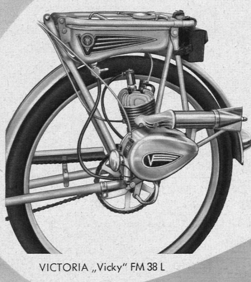
| Left: Victoria FM38 motorwheel: 1946
The engine was a single-cylinder two-stroke of 38 cc. Cylinder diameter was 35 mm, and the stroke 40 mm. Power was claimed to be 0.8 HP at 4000 rpm. There was a twist throttle handle for mounting on the handlebars, and a Noris flywheel magneto with lighting coil, giving 3 watts at 6 Volts.
There was a gearbox integrated with the engine block giving two gears, controlled by a lever on the handlebars. Drive to the rear wheel was by chain.
For some time both ladies and gents versions were available. This is a ladies model.
|
 |
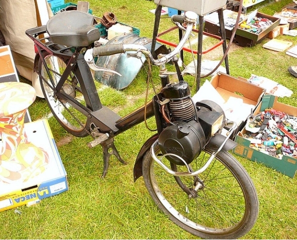
| Left: 1951 Victoria bicycle with Victoria FM 38 engine attached: 1951
The petrol tank held approx 3 litres of petrol-oil mixture.
Fuel consumption: was claimed to be approx 1.5 litres per 100 km at a speed of 30 km/h.
The weight with engine, fuel tank, luggage rack and all accessories was 11.5 kg.
|
 |
| Left: bicycle with Victoria FM 38 engine attached: 1951
|
 |
| Left: bicycle with Victoria FM 38 engine attached: 1951
|
 |
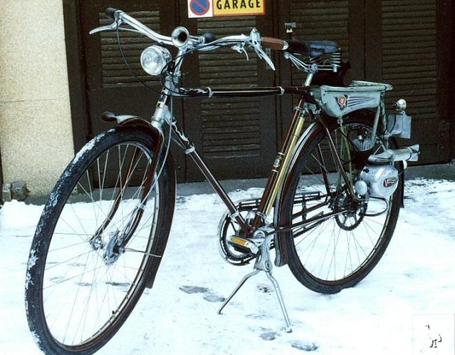
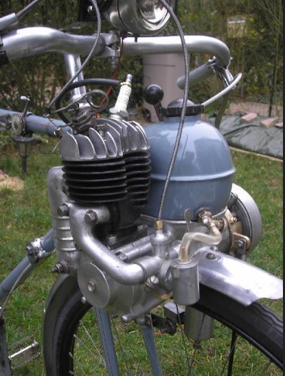
| Left: La Poulain motorised bike: 1949
This machine is powered by a Model A 50cc engine. The silver lever next to the handlebars (barely visible) raised the engine friction-roller off the tyre, and so acted as a clutch.
There is more information here.
|
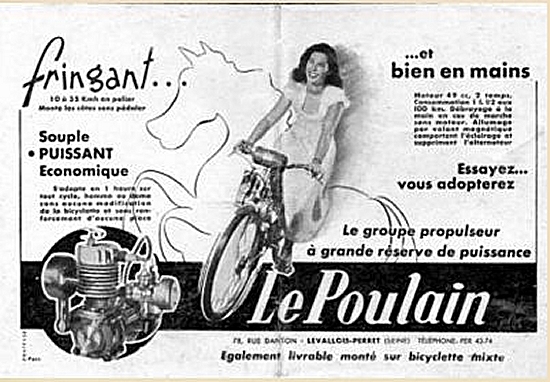 |
| Left: La Poulain motorised bike: 1949
This advert shows a later engine design. Simple, powerful, and economic, apparently.
|
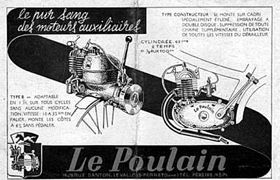 |
| Left: La Poulain motorised bike: 1949
This advert shows a later engine design.
|
 |
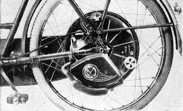
| Left: La Poulain motorised bike: 19??
Found on the Web. All I know is that it is a monobloc type-B, according to the filename of the image
There is more information here.
|
 |
| Left: Early Cyclemaster motorised wheel: 1950
The Cyclemaster, along with the BSA Winged Wheel, was one the most popular cyclemotors in Britain. It was launched in Britain in June 1950. It was a package of engine and rear wheel.
|
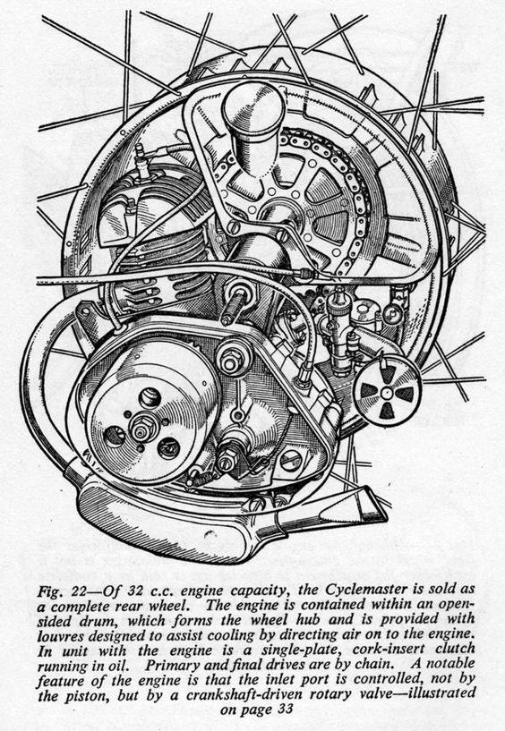 |
| Left: Cyclemaster motorised wheel: 1950
The engine cylinder is nearly vertical, which distinguishes it from the BSA Winged Wheel, which had a horizontal cylinder. The carburetor is at lower right, with a closeable opening to give a choke affect. The silencer is the curved box at the bottom of the diagram. Note the final chain drive to the wheel.
The engine had a bore and stroke of 32 mm and a capacity of only 25.7 cc. Maximum power output was 0.6 HP at 3,700rpm. (15mph road speed) Fuel consumption was claimed to be 300 MPG at 18mph.
There is more information here.
|
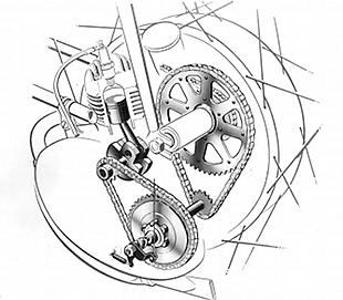 |
| Left: Cyclemaster cyclemotor: 1950
Drive reduction on the Cyclemaster was by two chains.
Note there is quite a serious reduction ratio of 18:1, as the very small engine has to turn at high rpm to produce enough power. Note the tiny piston.
|
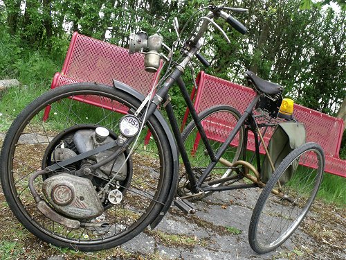 |
| Left: Cyclemaster cyclemotor: 1950
An unconventional mounting for a Cyclemaster, on the front wheel of a tricycle. The front-wheel fitting requires a torque reaction arm, the black bar sloping up towards the tax disc. There is a third brake lever, ingeniously arranged to operate the Cyclemaster's coaster brake. Note the acetylene headlamp.
Photograph taken at the East Anglian Run on 19 May 2013.
|
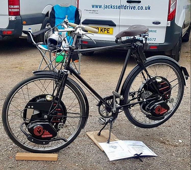 |
| Left: Cyclemaster cyclemotor: 1950
Another unconventional mounting, with a Cyclemaster on each wheel, should give double the power and commensurately better performance. It seems likely it would be quite a handful to ride. It is probably a modern construction.
An image search failed to find any information at all about the machine, date, or location.
|
 |
| Left: GYS Motamite cyclemotor: 1950
This GYS Motamite cyclemotor is owned by Dave Whatling; it was built in 1950 and has roller-drive to the front tyre. The engine was a 49cc two-stroke with a deflector-top piston that was claimed to give 1.2 HP at 3500 rpm. Later versions were marketed as the Cairns Mocyc. Make of bicycle unknown.
There is more information here, and here, and here.
Photographed at the Radar Run on 13 Apr 2008
|
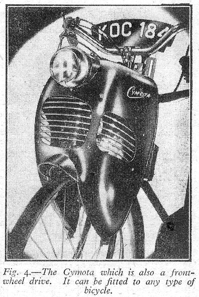 |
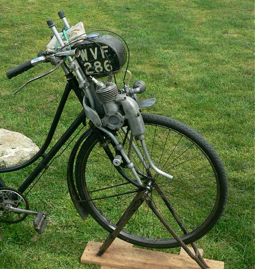
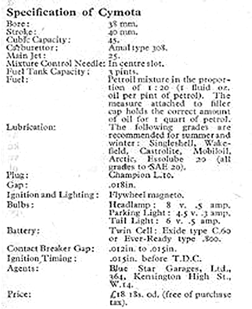
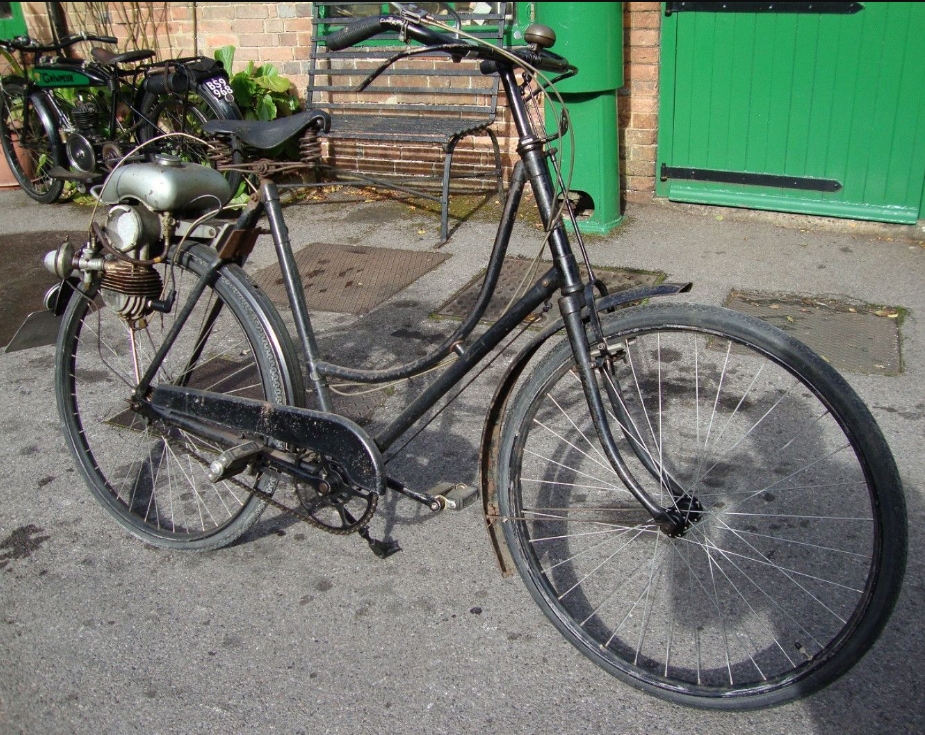
| Left: The Cymota: 1950
The Cymota had a very neat cowling to hide the works. Drive was by friction roller to the tyre. The two-stroke engine used a deflector type piston.
It had a short life, being made from 1950 to 1951 only at Erdington, Birmingham and sold by Blue Star Garages in London.
There is more information here.
Source: Newnes Practical Mechanics for August 1950.
|
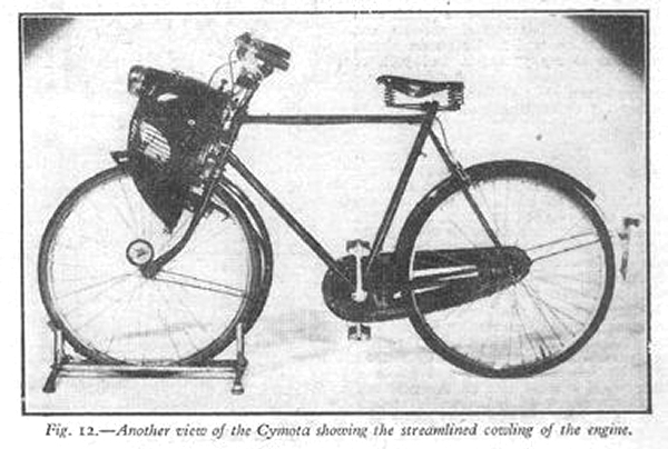 |
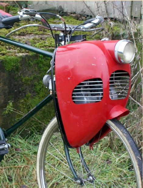
| Left: The Cymota: 1950
The Cymota fitted to a bicycle of unknown make.
Source: Newnes Practical Mechanics for August 1950.
|
 |
| Left: The internals of the Cymota: 1950
The crankshaft drove directly on the friction-roller. Note flywheel magneto and the presence of a decompressor valve to aid starting.
The engine could be raised from the wheel by use of a lever. (top left)
Source:
|
 |
| Left: The Cymota: 1950
The specifications. Note the power output from the 45 cc engine is not given.
There is more information here.
Source: Newnes Practical Mechanics for August 1950.
|
 |
| Left: The Cymota: 1950
A refurbished Cymota fitted to a Raleigh Superbe Tourist Gents Bicycle. Very neat.
|
 |
| Left: Power Pak engine and Goddard bicycle: 1951
This shows a 1951 49cc Power Pak engine fitted to an early Sinclair Goddard bicycle.
There is more information here.
|
 |
|
Above: Tube Investments Power Wheel rotary engine: 1951
This is a unique example of a rotary cyclemotor; here 'rotary' means that the engine rotates around a stationary crankshaft, as in early aero-engines. It is not a rotary-piston design like the Wankel. It was designed by Cyril Pullin, who was also already well-known for the Pullin-Groom and Ascot-Pullin brands of motorcycle.
The stroke was 35 mm and the bore 38 mm, giving 40 cc. A decompression valve was fitted opposite the spark plug. Drive to the axle was via two pairs of spur gears. The power output is unknown, but it could drive a bicycle at 18 mph in tests.
The Power Wheel was a last-minute exhibit at the Earl's Court motorcycle show in 1951, but it appears not to have been put into production.
Source: Motor Cycling for 29 Nov 1951
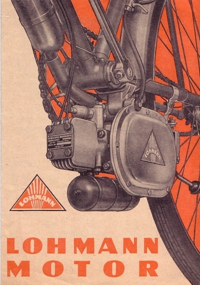 |
| Left: Lohmann compression-ignition motor: 1952
The Lohman cyclemotor was an unusual 2-stroke compression-ignition German design meant to run on paraffin; it had variable compression controlled by a twistgrip. It was mounted beneath the chainwheel of a bicycle. Drive was by a rubber wheel pressing on the underneath of the tyre. Most roller-drive cyclemotors had the roller on top of the tyre.
It was claimed that the Lohman could achieve 350 miles per gallon, but as far as is known this was never proven.
There is more information here.
|
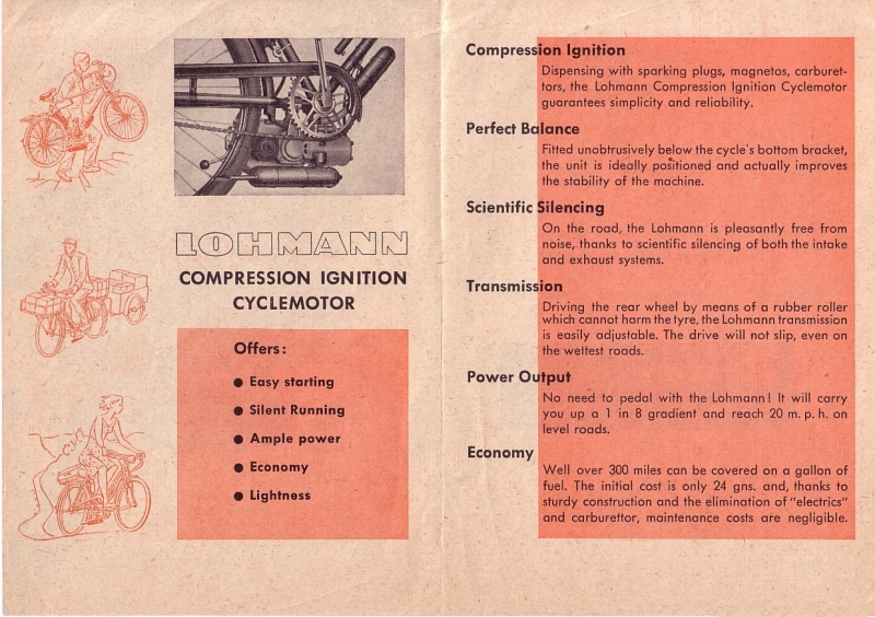 |
| Left: Lohmann compression-ignition motor: 1952
Although the motor was designed to run on paraffin, though it was sometimes described as a diesel engine; apparently in practice a carefully-judged mixture of diesel, petrol, and paraffin, plus 2-stroke lubricating oil, is required to make it work reasonably today. This suggests that customers would have been faced with some serious problems.
Note the claim that there was no need to pedal on 1 in 8 gradient; this seems very optimistic to me. Howver judging by the top left picture on the leaflet, you do have to carry it up stairs. The middle picture shows a man towing a trailer and with a front carrier on the bike. I don't think you're going to be sailing up 1 in 8 hills with that equipage; I'm not sure it would be much use on the level.
There is more information here.
|
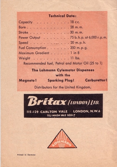 |
| Left: Lohmann compression-ignition motor: 1952
The power output is here stated as 75 BHP at 6000 rpm, truly impressive for 18cc; it must be a misprint for 0.75 BHP. The Lohman was imported by Britax in 1952 and 1953; quite a short time, and it seems likely it was not very popular.
There is more information here.
|
 |
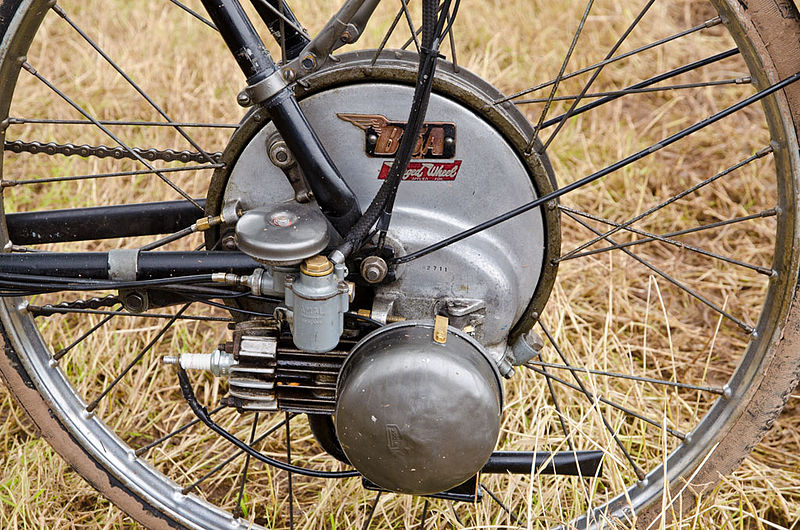
| Left: BSA Winged Wheel motorised bike: 1953
The BSA Winged Wheel was one of the most popular motorwheels in Britain; from its introduction in 1953 until 1957. It was a package of engine and rear wheel that weighed about 27 pounds.
Note the petrol tank on top of the rear mudguard. This held half-a-gallon; according to the manufacturer's figures that would take you 100 miles. Seems a bit optimistic...
|
 |
| Left: BSA motorised bike: 1953
The most popular of all the cyclemotor cycles in Britain was the BSA, primarily intended for mounting the BSA Winged Wheel engine. It was sold as a complete machine with a Winged Wheel factory-fitted, but could also be bought with no a rear wheel "for use with Motorised Wheels of all types".
The advertising blurb make a point of the fact that there is a positive drive by chain, rather than a slippery friction roller.
Note the need to give "slight assistance on the steeper hills."
|
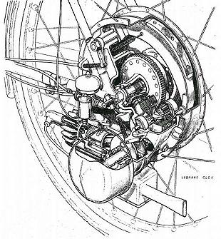 |
| Left: BSA Winged Wheel: 1953
The Winged Wheel had a single cylinder of 35cc with 36mm bore and 34mm stroke; BSA claiming one horsepower at 6,000 rpm, which is pretty fast rotation for the era. The cylinder had horizontal finning. Drive was by gears to the axle. There was a friction clutch but no gearbox.
The circular brake drum with its single internal shoe (which was considered by commentators to be very effective) is an integral part of the rear wheel. No adaptions to your own rear wheel possible here.
|
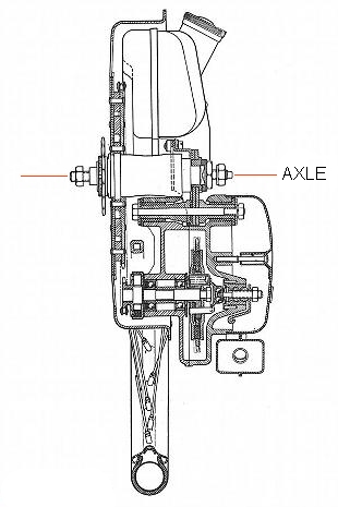 |
| Left: BSA Winged Wheel section: 1953
This drawing only shows part of the wheel; the axle is indicated by the red lines.
BSA sold its bicycle business to Raleigh company in 1957, and production of the Winged Wheel ceased. An impressive 29,000 units were sold; less than 300 are known to survive today.
There is more information here, and here
|
From a contemporary magazine article:
"A 35cc cyclemotor, to be called the Winged Wheel, is to be marketed by BSA. Designed to replace the rear wheel of a normal bicycle, the unit embodies gear drive transmission through a three-plate clutch, a 9�in-diameter in�ternal expanding brake and a heavy duty free-wheel of the locking roller type. Complete with control cables and levers, tyre and tube, fuel tank and fittings, the unit will retail at �25."
"The two-stroke engine is incorporated in a 26 x 1�in cycle wheel with the cylinder, horizontally disposed, in line with the cycle frame; the cylinder head faces for�ward into the air stream. Strengthened by heavy duty spokes, the wheel can be fitted to most types of standard bicycle. A separate fuel tank of half-gallon capa�city is intended to be fitted in the carrier position above the rear wheel. Weight of the engine-wheel unit is given as just under 27 lb."
"Bore and stroke measurements of the engine are 36 x 34mm. The cylinder is machined from high-grade cast iron and is finned horizontally. At its top (or for�ward) end, the cylinder is spigoted to receive the light-alloy cylinder head, which has a hemispherical combustion space - and a centrally disposed boss for the long-reach sparking plug. Cylinder and head are secured to the crankcase, by four long studs and nuts and special saddle washers which bridge four pairs of adjacent head fins. Diametrically opposed inside the barrel, the outlet ends of the transfer ports are flared to impart a swirl to the compressed charge from the crankcase."
"The carburettor is an Amal, fitted with an unusual strangler operated from the throttle lever. The aim, of course, is to keep the number of controls down to the minimum. This is achieved by employing a throttle lever fitted with a small ratchet which, when lifted, allows the lever to be moved past the position where the throttle is fully open. Movement of the lever beyond this point causes the blind end of a groove in the throttle slide to actuate a small tongue on the end of the pivoted strangler butterfly valve. Thus the valve is brought down to blank off the choke tube in order to provide the necessary rich mixture for cold starting."
"A low-expansion, silicon-aluminium alloy casting, the piston is of the slightly domed, deflectorless type and carries two pegged compression rings. The gudgeon-pin is fully floating, takes its bearing in a phosphor-bronze small-end bush and is retained by circlips. The big-end bearing consists of a single row of rollers which run between the crankpin and the hardened and ground big-end eye of the connecting rod. Material employed for the, connecting rod is case-hardened nickel-chrome steel with a tensile strength of 50 tons."
"The mainshafts and their webs are of medium-carbon case-hardened steel and, with the crankpin, form a three-piece crankshaft assembly. Parallel ground, the crankpin is an interference fit in the webs. Supporting the crankshaft are two 1 in �outside-diameter roller bearings, one at each side."
"Aluminium alloy is used for the crank�case castings. The inner, or right-hand, crankcase half is an integral part of a single, large casting which forms the shoe-plate of the brake as well as an enclosing shell to house the clutch and gear trans�mission mechanism. The outer, or left-hand, portion of the crankcase carries a roller journal bearing and a pressure oil seal, and it is extended to form a spigot on which the stator of a Series 90 Wico�Pacy mag-generator is mounted. The rotor, of course, is -carried on the left-hand side engine mainshaft. The Series 90 mag-generator is the latest version of the Bantamag and was fully described in The Motor Cycle for 11 September, 1952. For the Winged Wheel, the generator is fitted with a separate cloth cover, retained by a spring clip."
"The right-hand main-shaft is splined to carry a 17-tooth spur pinion which, situated in the transmission box, drives the clutch through a 66-tooth gear pinion on the clutch drum peri�phery. When the clutch is engaged, the drive is transmitted from a pinion on the clutch shaft to a fourth pinion in the gear train. This last pinion is riveted to the wheel hub, which is keyed to the large-diameter brake drum."
"The clutch shaft is carried by two ball jour�nal bearings, one at each end. One bearing is housed in the combined crankcase and brake cover plate (which houses also one of the main wheel bearings). The other bearing is housed in a secondary cover plate which closes that portion of the main shell in which the transmission is installed."
"Loading the clutch pressure plate are no fewer than ten small coil springs located in thimbles. The springs are manufactured in 18 swg. wire, are 7/16in diameter and have a 24 lb pressure rating. Cork inserts are used in the fric�tion plates. A short clutch pushrod is actuated by a cable-operated bell-crank mounted on the outside of the transmis�sion housing. The entire gear train runs in oil. Synthetic rubber oil seals are fitted on the dutch shaft and in the hub assembly as well as on the crankshaft."
"Apart from its large diameter, the brake is unusual in that each shoe is mounted on a separate pivot. Operation is by means of a single, parallel cam. The shoes are linked by means of a single return spring situated close to the cam. In order to eliminate any possibility of chatter, each shoe has a locating screw which is inserted into the shoe plate and operates in a slot midway between the shoe pivot and the cam. Dimensions of the linings are 5�in long x 5/8in wide. Brake operation is by cable from a handlebar lever."
"The silencer comprises a box-section expansion chamber and short discharge pipe. The unit is readily dismantled for cleaning purposes. Its lid is retained by one nut and, on its removal, the single baffle plate can be withdrawn."
"Power developed by the wheel, it is stated, is sufficient to propel an ordinary cycle at a cruising speed of 20 mph; maximum speed is approximately 26 mph. Fuel consumption is expected to average around 200 mpg."
"Last week a member of the staff of The Motor Cycle rode a bicycle fitted with a prototype model of the Winged Wheel. Starting with the engine either cold or warm was accomplished after a few easy turns of the pedals. The pro�cedure was to pedal off with the clutch held out, and, with the throttle lever set at about one-third open, engage the clutch when a fast walking speed had been reached. The engine appeared to be quite happy, and two-stroked per�fectly, at speeds in the region of 20 mph. Maximum speed achieved on level ground was 25 mph. At the lower end of the scale, the engine pulled extremely well. The large rear brake was most effective, and was endowed with sufficient spongi�ness to provide true delicacy of control. Power on hills was well sustained. After a baulk on average main-road gradients, the pedal assistance required was of a light nature. There was no vibration, and roughness was perceptible only when the engine was made to pull at inordin�ately low speeds."
|
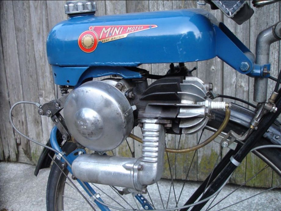 |
| Left: The Trojan Mini-Motor: 1957
When I was but a lad, an old lady called Mrs Young lived next door, and she had a bicycle with a little engine above the rear wheel. To the best of my recollection it was one of these Trojan Mini-Motors, though it had a green rather than blue tank. I never got the chance to examine it, as she was (in my mind at least) a rather intimidating person.
The Mini-Motor was a 2-stroke with a bore of 38mm and a stroke of 44mm, giving a capacity of 49.9 cc. Output was claimed to be 1.5 HP at 3000 rpm, corresponding to 20 mph. It had no gears, and drive to the rear wheel was by a friction roller mounted on the crankshaft. It had no decompressor (additionally at least- one was later added) which could make starting tricky if the friction roller slipped rather than overcoming the engine compression.
There is more information here, and even more information here, including a complete parts list.
|
Roller slippage was always an issue with this sort of drive; slipping not only caused loss of power, but would damage the tyre. The engine and tank had a pivot at the front, allowing the engine to be raised so the roller was clear of the tyre, giving a sort of neutral gear; this was operated by the grey cable at left.
 |
| Left: VeloVap motorised bike: 1959
Here the engine is an integral part of the bike. Note small petrol tank behind the saddle. Presumably a pipe ran forward to the engine through the central tube.
|
 |
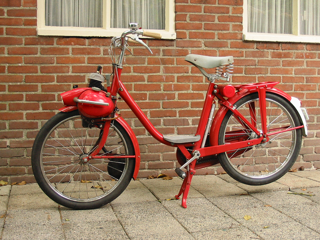
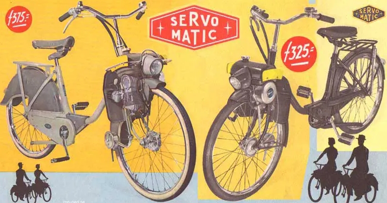
| Left: 1951 Avaros Ideal Servo-matic de Luxe motorised bike: 1951
Another engine over the front wheel. What (if anything) Servo-matic meant is currently unclear. Drive was probably by friction roller. A neat installation.
Note ignition cable running over the mudguard to the flywheel magneto on the other side. Looks like the cable has become detached from the sparkplug.
|
 |
| Left: 1951 Avaros Ideal Servo-matic de Luxe motorised bike: 1951
The Avaros company was based in Papendrecht, in Holland, and was named after its creator, Albert van Rossum.
|
 |
| Left: 1951 Avaros Ideal Servo-matic de Luxe motorised bike: 1951
The Alvaros has a 49 cc engine with a bore of 39.5 mm and a stroke of 40mm.
There is more information here.
|
 |
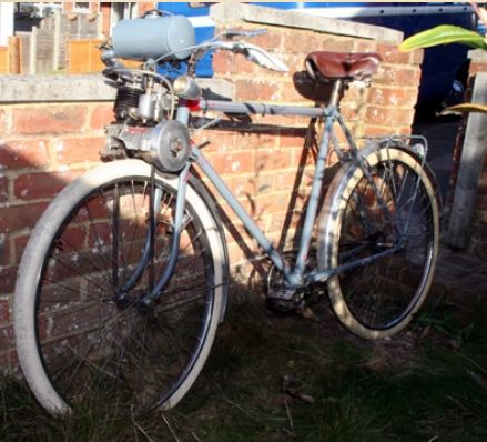
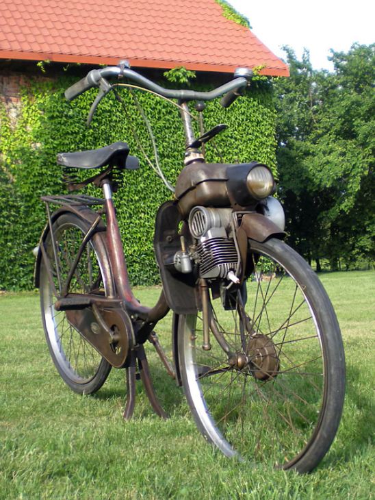
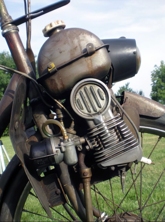
| Left: HMW-Fuchs motorised bike: 1953
This Fuchs motorwheel/cyclemotor is a attached to a restored Austrian HMW bicycle. The motorwheel was made by the same company, so the engine was very likely attached at the factory.
Note the logo on the engine- 'Fuchs' is German for fox. The engine was called a Hilfsmotor, ("help-motor") indicating it was only capable of doing part of the work of moving the bicycle. Some LPA required...
There is more information here. The site says the bicycle is from 1949, while the engine dates from 1953, which suggests it was in fact an aftermarket attachment.
|
 |
| Left: HMW-Fuchs motorised bike: 1953
A view of the complete motorised bike.
|
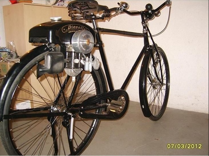 |
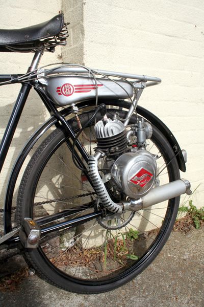
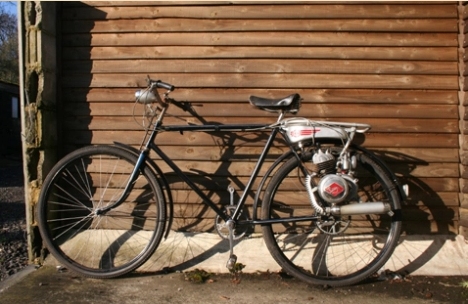
| Left: Motorised bike with Diesella engine: 1951
The Diesella was a Danish design. It had a 50cc 2-stroke engine and despite the name ran on petrol. Drive was by roller on the rear wheel, with a lever (on the other side) to lift it off and give the effect of a clutch. Note the inverted cylinder. Apparently they had the nickname "ass pusher".
You can see a Diesella on test on YouTube.
There is more information here.
|
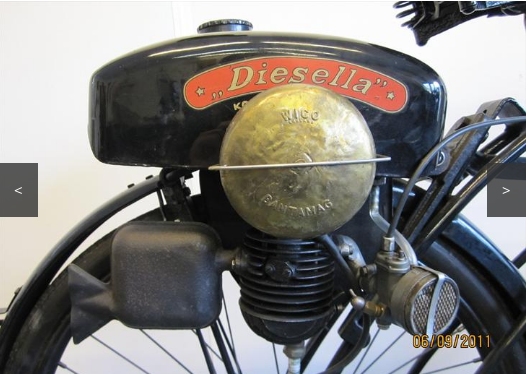 |
| Left: Motorised bike with Diesella engine: 1951
You can see a video of the Diesella starting up on YouTube.
The brass round thing has WICO BANTAMAG stamped on it, so it's a safe assumption it is a flywheel magneto.
There is more information here.
|
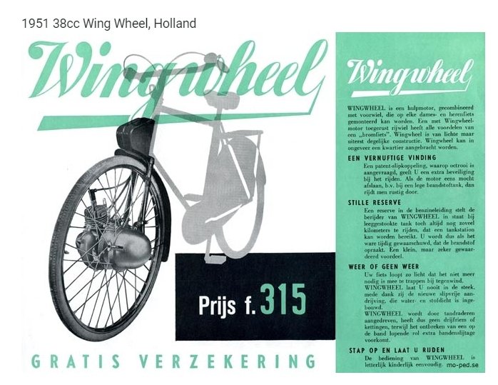 |
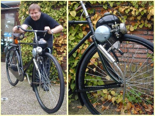
| Left: Wingwheel bike from Holland: 1951
This design is unusual because it has the engine at the front, but attached to the hub rather than sitting above the wheel. The only other example in this gallery is the Peugeot Cyclomoto of 1922.
It has nothing to do with the BSA Winged Wheel, which was rear-wheel mounted.
The black thing above the wheel is presumably the petrol tank. I have not got round to translating all the Dutch, but since the rest of the bicycle is greyed out, it looks as though the Wingwheel was a package of wheel, engine, and front forks.
'Gratis verzekering' means 'free insurance'.
|
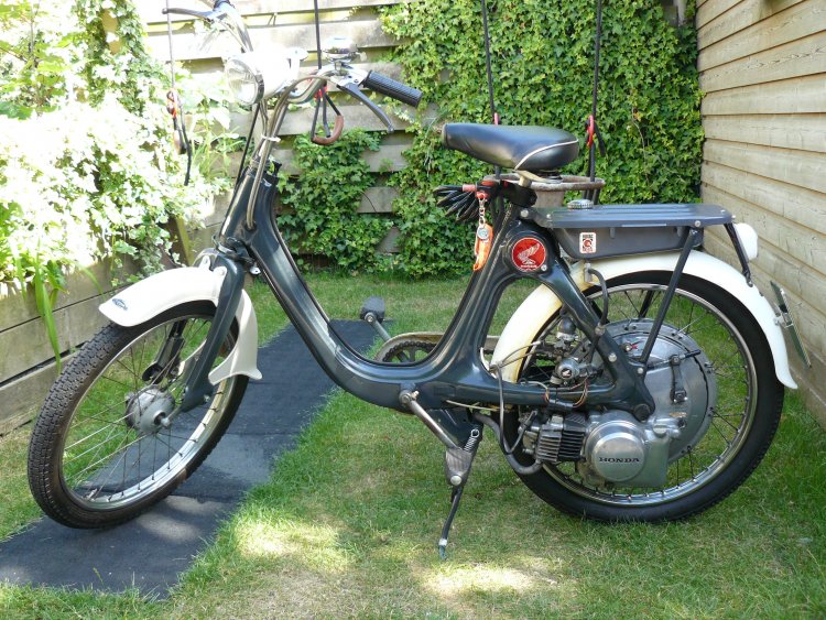 |
| Left: Honda P50: 1966
The Honda P50 was the last motor-wheel moped design by Honda; it was unusual in having a 49 cc four-stroke engine (most motor-wheels were two-stroke) with a chain-driven overhead camshaft; quite sophisticated. An exhaust-valve lifter was fitted. It is alleged by some sources that the P50 had a continuously-variable transmission; that sounds intriguing, but confirmation is currently lacking. The workshop manual says:
"POWER TRANSMISSION IS PERFORMED by a specially engineered three stage speed reduction and a reliable centrifugal clutch that automatically disengages at idling speed and engages when throttle is opened, eliminating any need for a manual clutch or gear shift."
That sheds little light. In the section of the manual that deals with the transmission we are told that there is no transmission, which is obviously untrue:
"The transmission of the rotating power generated at the engine to the rear wheel is made possible by the power transmission mechanism. The P50 is not equipped with a transmission, however. all the speed reducing operations is performed by chains which also drives the rear wheel. (Fig. 3- 57 )
(Gears are used on P50 for Holland export type)" Presumably they meant it was not fitted with a gearbox.
|
Speed reduction is certainly by three chains in series, but there is no reference anywhere in the manual of any way to change gear ratios.
Production ceased in 1968.
The P50 has a brief Wikipedia page.
 |
| Left: Homemade motorised bike with Berini engine: 1950
The bicycle is a Dutch Gazelle from 1927 with an original "Eton Minor" luggage carrier; Gazelle are still very much in business. The engine is a Berini M13 2-stroke 32.5 cc hulpmotor. ("help-motor") It was made between 1950 and 1952 and has a speed of 30 to 35km/h.
There is more information here.
|
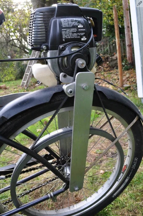 |
| Left: Homemade motorised bike using a Honda engine: date unknown
The engine is a Honda GX31 4-stroke with centrifugal clutch, bought second-hand on Ebay for about $80. Drive to the rear wheel is by toothed-belt.
The bike can reach 30mph on the flat. It was built by Ghost Wolf, who gives much more information here.
|
There is an excellent selection of motorised bicycles and mopeds (there is a very blurred line between them) at motorbicycling.com.
|


