For many years power was distributed around London by a high-pressure water supply, provided by The London Hydraulic Power Company. It allowed power to be distributed long before electric power networks were possible, and used on sites where a steam engine and its associated boiler would be impractical. Water was supplied at a nominal 800 psi (5.5 MPa or 55 Bar) pumped by five hydraulic power stations, originally driven by coal-fired steam engines, and later by electric motors.
In most cases water was pumped from the nearest river, and into a tank where mud and sediment settled out. The demand for water would vary continuously, and this was accomodated by hydraulic accumulators that were enormous weights resting on hydraulic cylinders.

THE LONDON HYDRAULIC POWER COMPANY (BRITAIN)
The London Hydraulic Power company was the largest network in Great Britain; it began active operation in autumn 1883. It was not the first- the Hull system became operational in 1876.
The first London pumping station was built at Falcon Wharf, Holland St, at Bankside, east of Blackfriars Bridge, on the south bank of the River Thames. The site presumably disappeared when Bankside power station was built, but Holland Street still exists. Bankside power station is now the Tate Modern art gallery.
|
|
|
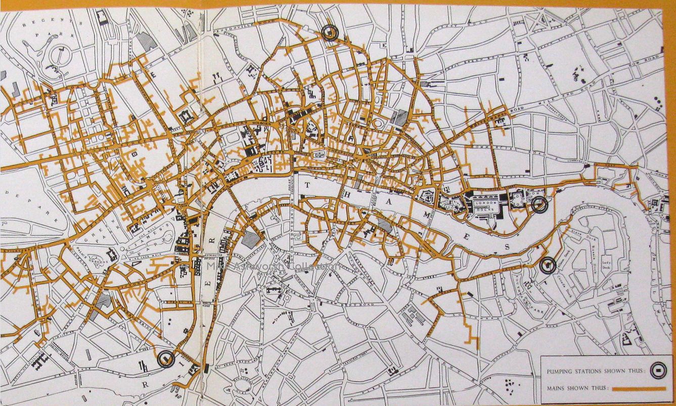
Above: The London hydraulic network in 1960, at its fullest extent.
Just to the west of Tower Bridge (to the left of the M in THAMES) hydraulic mains can be seen crossing under the Thames through the Tower subway.
Further east, (to the left of the S in THAMES) another branch of the network runs under the Thames. It would not have been economic to dig a tunnel under the river for a few pipes, so I suggest that they ran below the river in the abandoned tunnels of the City & South London Railway, (Now the Northern Line) that ran from Bor station to King William Street. (It was abandoned to allow straighter alignments when the line was extended north to Moorgate) The shape of the branch on the map above follows the route of the old tunnels.
|
The London pumping stations were:
- Falcon Wharf, Holland St SE (1883- )
- Philip Lane EC, City of London ( - )
- Kensington Court (18??-1893)
- Millbank SW (1887-)
- Wapping E (1890-1977)
- City Road Basin (1893-
- Rotherhithe (1903- )
THE WAPPING STATION
The best-known of the stations is Wapping Hydraulic Power Station, which still exists and contains pumping machinery which is allegedly in working order, though I think that is perhaps questionable. There is much more detailed information about the Wapping station here.
Until (I think) 2013 the main pumping hall at Wapping contained a very good (though rather expensive) restaurant, that I and my partner visited several times. Another part of the building housed an art gallery and performance space. I find in my records, Watson, that I last dined there on Wednesday 13 June 2007; foie gras, pork, and chocolate & marmalade ice-cream were consumed; very nice. It closed some years ago; a definite loss.
Business on the London system began a slow decline from 1904, as electricity distribution improved. By 1973 only two pumping stations were operational. The London Hydraulic Power Company went into voluntary liquidation in 1976.
OTHER BRITISH NETWORKS
Similar hydraulic networks were built in Birmingham, Hull, Liverpool, Manchester, and Glasgow; see:
There is a general Wikipedia page on hydraulic power networks.
THE ANTWERP SYSTEM (BELGIUM)
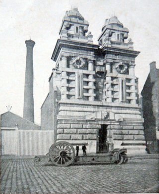 |
| A former hydraulic pumping plant in Antwerp in Belgium. The twin towers housed two hydraulic accumulators
This building was called the 'Zuiderpershuis' which tranlates literally as 'Southern press house' implying there there were at least two of them; presumably there was a 'Northern press house'.
The Antwerp system not only supplied mechanical power; it was also used for the local generation of electricity, its distribution over any distance being then uneconomical. The Paris compressed air network was also used for local electricity generation, and must have been even more inefficent, due to the energy lost as heat when air is compressed.
There is a Wikipedia page. See also below
|
THE GENEVA HYDRAULIC SYSTEMS (SWITZERLAND)
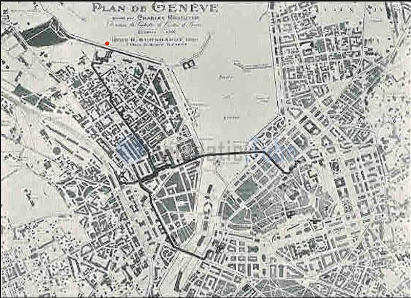 |
| A power water network in Geneva: date illegible
Note that the map is oriented with North-East at the top.
There were three water networks in Geneva, Switzerland. The first was the ordinary drinking water supply; its operating pressure is currently unknown.
The second was the medium pressure power network. It had an operating pressure of 6.5 bar (94 psi) and reached a total length of 82 km by 1896. It was used for powering 130 Schmid-type water engines. Albert Schmid (1847-1915) was a Swiss mechanical engineer. The total power is stated to have been 230 HP. This doesn't seem very much; less than 2 HP per engine, but the power network mostly supplied small businesses, especially the important Swiss sector of clock and watchmakers. 2 HP would drive a lot of watchmaker's lathes and drills, so it does make sense. The Grand Théâtre was also supplied, presumably to power scene-changing machinery.
The third was the high pressure power network which had an operating pressure of 14 bar (203 psi) and reached a total length of 93 km. It was used to power 207 turbines and water-engines, as well as operating lifts, which don't require a lot of water but do need a lot of pressure. The total power was 3000 HP, so it must have pumped a good deal more water than the medium pressure network.
The map presumably shows only one network- either the intermediate or the high pressure one. The pumping station was on the edge of Lake Geneva and is marked 'III ' at top left; see red dot. Note the short branch supplying what appears to be a main railway station; possibly to power winches that moved goods wagons.
|
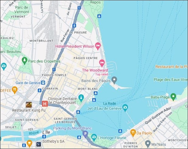 |
| A Modern Map of the same location
North is at the top (as it should be) this time.
|
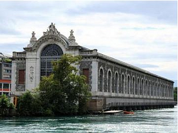 |
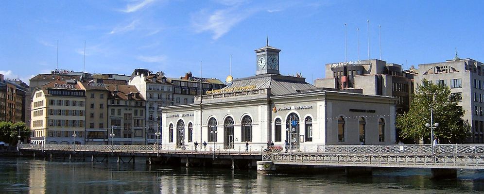
| The water power plant at Geneva
The Power Plant Building (Bâtiment des Forces Motrices) housed water turbines that generated hydroelectricy, and powered the water supply and hydraulic power networks in Geneva. Situated close to where the Rhône River leaves Lake Geneva, (heading for Lyon) it was built between 1883 and 1892. Its purpose was to harness the river's flow to generate water pressure for Geneva's water supply and to operate a hydraulic power network. Additionally, its weir was crucial in managing Lake Geneva's water levels.
There is more info on the Power Plant Building here
|
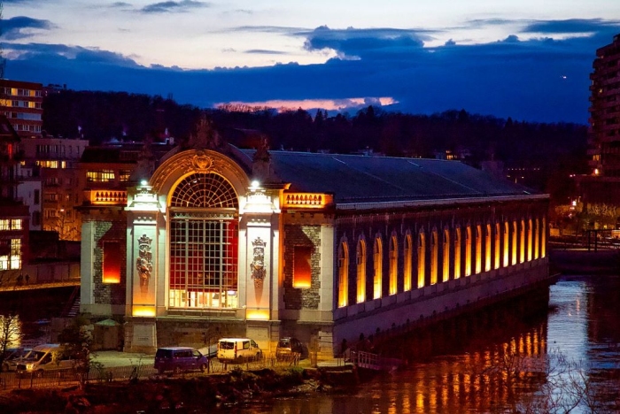 |
| The water power plant
Although the turbines in the building ceased to drive the power water networks in 1963, they continued to pump Geneva's drinking water system until 1988. The weir remained operational until it was replaced by the Seujet Barrage (Wikipedia page in French, but Google translates it nicely) in 1995, which is some fifty meters downstream. It was reopened in 1997 as an opera house and concert hall, and very impressive it looks too when lit up at night.
Although the turbines in the building ceased to drive the power water networks in 1963, they continued to pump Geneva's drinking water system until 1988. The associated weir remained operational until it was replaced by the Seujet Barrage (Wikipedia page in French, but Google translates it nicely) in 1995, which is some fifty meters downstream. It was reopened in 1997 as an opera house and concert hall.
|
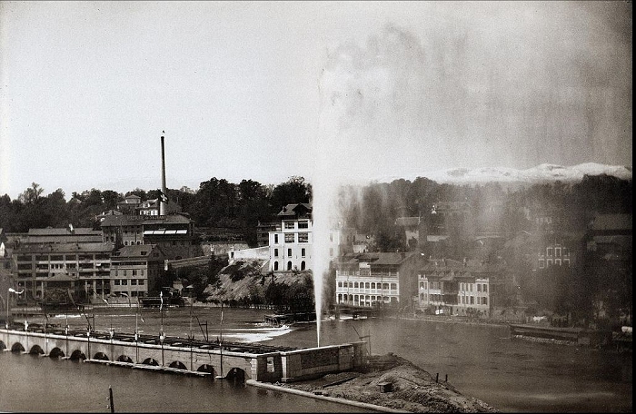 |
| The original overpressure fountain in action
Geneva is famous for its giant fountain, (the Jet d'eau) which today is purely decorative. However, the original fountain was a practical part of the hydraulic power system. Its purpose was to relieve the pressure in the system when the various engines closed down at the end of the working day; this clearly wasted energy. Why this was thought necessary is not clear; the London network had nothing of the kind; what it did have was a number of hydraulic accumulators to accomodate excess water. In Geneva the fountain was removed when a better solution was found; what it was is currently unknown.
This begs the question that if there were two high-pressure networks, would there not have to be two fountains? Presumably the problem was much worse on one rather than the other; this is currently unclear.
When the fountain was taken out of use there was a public outcry, and the current fountain was installed There is more info on the Jetd'eau fountain in Wikipedia.
|
THE HISTORY OF GENEVA'S PUMPING STATIONS
The first water-driven pumping station in Geneva was built in 1709, and gave name 'The Pont de la Machine' to the bridge adjacent. It was built at the entrance to the left arm of the Rhône by Joseph Abeille to pump water from the river to feed Geneva's fountains. No image of it has been found so far.
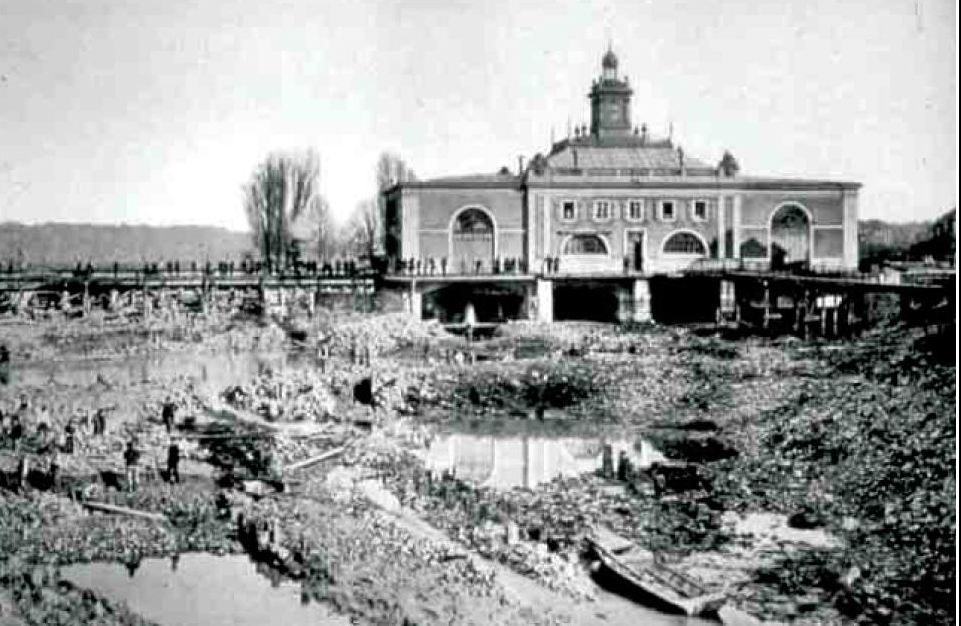 |
| The second water power plant, built 1841
The second water-driven power house was built in 1841, designed by Jean-Marie Cordier. It was built roughly in the center of the bed of the Rhône.
This picture shows the second water power plant at the end of its working life in 1887, when a section of the Rhone had been dried out during the construction of the third and final power house.
|
 |
| The second water power plant today
|
Hydraulic power networks were also built in other countries:
OTHER WAYS OF TRANSMITTING POWER
Power can also be distributed by a compressed air network such as the extensive system in Paris. This is however much less efficient because of the heat lost when compressing the air. Water by comparison is almost incompressible and the equivalent losses are negligible.
Power distribution can be mechanical over short distances. Perhaps the most dramatic example is the Great Machine of Marly, (Wikipedia) built in 1684 amd powered by waterwheels which pumped water from the Seine up to the Palace of Versailles. (Wikipedia)
The typical 19th-century factory would have horizontal line shafting mounted just under the ceiling, with a drive belt linking it to individual machines. One mid-19th-century factory in the USA had 1,948 feet of line shafting carrying 541 pulleys in its finishing shop.


