The city of Paris once had an extensive network for distributing power by compressed air. London, Manchester, and Liverpool had hydraulic power distribution networks, and there were others in Antwerp, Australia and Buenos Aires, but the compressed air network of Paris was unique. Attempts were made to set up a network in Birmingham, but these failed.
There is an immediate objection; transmitting power by compressed air is horribly inefficent, because all the heat created in the compressor is lost long before the air gets to the point of use. Nonetheless the Paris network flourished for many years. Factory-wide compressed air networks for driving power tools are commonplace, but only Paris had a city-wide network.
The roots of the system go back to 1879 when the Austrian engineer Viktor Popp set up the Compagnie des Horloges Pneumatiques (CGHP)to drive pneumatic public clocks with one air pulse per minute, after authorization to install a compressed air network was granted by the City of Paris.
At the time compressed air was in the air, so to speak, following the extensive use of compressed air for rock drilling in the construction of the Mont Cenis tunnel, which was initially expected to take 25 years but was opened in 1871 after only 14 years following the introduction of pneumatic equipment. (Dynamite was also a help in the later years of construction) At the time there was much debate as to the best way of transmitting power over a distance; electricity was in its infancy, but high-pressure water had proved highly successful
Popp obtained French nationality in 1881. In 1886 he was licensed to distribute compressed air continuously as a general source of motive power. In 1889 he obtained a further municipal concession to supply electricity by using the compressed air power network to drive local electrical generators. Large amounts of power were handled by converted steam engines, but small amounts by a rotary air engine introduced and patented by Popp; this intriguing device is described below.
For several years Popp ran the company as director of the Compagnie Parisienne de l'Air Comprime. (CPAC) However in 1892 the German banks who had provided most of the capital for the rapid expansion of the power network took over control, and Popp was forced to resign. (The involvement of the Germans did not sit well with the French, who had not forgotten the Franco-Prussian war) He then turned his attentions to compressed-air traction, and the growing motor industry. Popp was later involved in the Branly-Popp radio system.
In 1888 Viktor Popp installed a 1,500 kW compressor plant at 16 Rue St-Fargeau, in Belleville, a district in the north-east of Paris. That grew to 18,000 kW by 1891. Another usine (power-house) was built later at Quai de La Gare.
THE PARIS COMPRESSED AIR NETWORK
 |
|
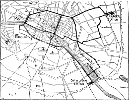
Above: The Paris compressed air network in 1889. The St-Fargeau usine is off to the extreme right, marked by a red dot.
|
 |
| Left: The Paris compressed air network: 1891
The original Rue St-Fargeau compressing station is at top right. The location seems to have been dubiously chosen as it had no direct rail access for delivering coal; this presumably came by cart from the nearest railway which was the Petit Ceinture, but old maps show no nearby goods yard. It was much better sited for a supply cooling water for the condensers; this presumably came from the nearby Menilmontant reservoir, which was fed by the Dhuis Aqueduct; this was not an aqueduct carried on arches but an oval masonry conduit running underground. The area of Menilmontant is the highest part of Paris and the reservoir was placed there so it could supply water by gravity to the top floors of buildings in the city. Another convenience, the first electric elevators, came into use in the late 1800's. Not only did elevator technology make it easier to reach the top floors of a building faster, the use of elevators meant heavy equipment could be moved much easier.
The later Quai de La Gare usine was built adjacent to both the Ceinture (for coal) and the Seine. (for water)
The bobbly line is the the defensive Thiers wall built around Paris between 1841 and 1844. It was demolished in sections between 1919 and 1929.
Note that this map appears to show the Petit Ceinture ending at the Cemetery Pere Lachaise; actually it went (and indeed goes, though the line is disused) underground at this point.
|
As the network grew, inventors were rapidly patenting air motors, clocks, and even beer dispensers. One claimed advantage of compressed air over electricity was safety. Electric cables can short and catch fire spectacularly, and there is always the risk of electric shock. In contrast, the worst that could happen with compressed air was a burst pipe; this would not be a good thing to be standing near, but since the pipes ran through the sewers the chance of this was very small.
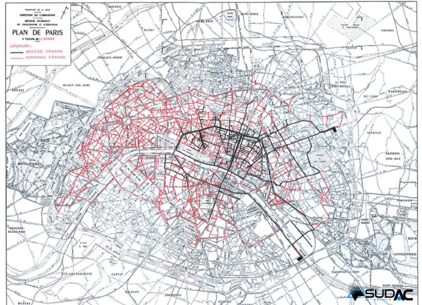 |
| Left: The Paris compressed air network: 1911
Black shows the ancien reseau (old network) using 12-inch diameter pipes, while red shows the nouveau reseau. (new network) using 20-inch diameter pipes.
The Quai de Gare usine is the black rectangle at lower right, next to the Seine.
|
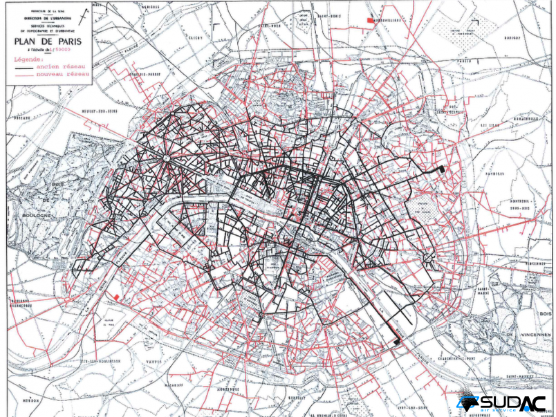 |
| Left: The Paris network: 1962
Black shows the ancien reseau (old network), while red shows the nouveau reseau. (new network)
This map is believed to show the compressed-air network at its greatest extent. There are now many mains extending outside the Thierry wall line.
The red block at top right is the new usine at Abbevilliers, opened in 1961 to serve industry that had moved from the centre of Paris to the north of it.
In 1959 SUDAC had over 900 km of pipes.
|

THE ST-FARGEAU USINE
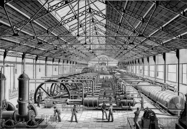 |
| Left: The St-Fargeau usine: 1889
This shows a row of horizontal steam-driven compressors. The steam cylinders and flywheels are on the left and the compressor cylinders and air reservoirs on the right. The air was compressed to six atmospheres. (88 psi)
The boilers were in an adjacent hall to the left, and the steam pipes coming horizontally through the wall before dropping down to the engines are clearly visible.
Usine roughly means 'power-house'.
From The Manufacturer and Builder, July (?) 1889, p135. Courtesy Tom Bates
|
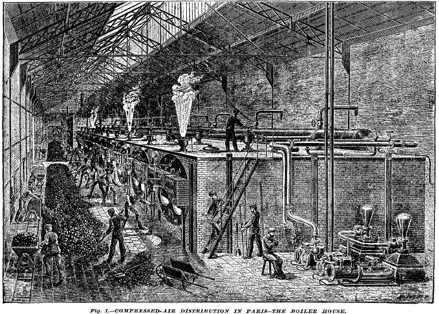 |
| Left: The boilers at the St-Fargeau usine: 1889
There are nine Paxman 'Economic' return-flue double-furnace boilers nearest the viewer. The boilers were 14 foot long and 7' 6" in diameter. Paxman was a British firm and this caused trouble later as people thought the machinery should be made in France. At the far end were two boilers of the Meunier type.
Three of the safety valves appear to be blowing off- a waste of steam and surely a hazard to the chap standing on top of the boilers. Two boiler feed pumps with air reservoirs can be seen at bottom right.
Running along the back of the boilers is the steam range- a large pipe collecting the steam from each boiler and distributing it to the engines so any combination of boilers and engines could be shut down as required for maintenance.
At the extreme left coal is brought in in tipping-wagons and placed in a long heap on the floor for the stokers.
All these boilers were connected to by underground flues to a 40-metre high chimney, with an internal diameter of 5.54 metres at the base and 3.1 metres at the top.
From The Manufacturer and Builder, August 1889, p182. Courtesy Tom Bates
|
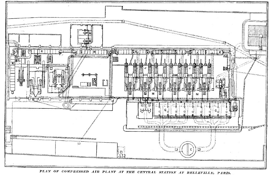 |
| Left: Plan of the St-Fargeau usine site: 1889
G = boilers
C = Chimney
c = compressor cylinders
M = steam cylinders
R = air reservoirs
The two pictures of the interior above are taken looking leftwards from the right-hand side of this plan.
From The Manufacturer and Builder, May 1889, p112. Courtesy Tom Bates
|
The original engines installed by Popp at St-Fargeau to drive the pneumatic clocks were two Farcot engines of 120Hp total output. The Farcot was a horizontal Corliss type of engine.
The first steam engine installed at St-Fargeau was a 350HP beam engine built by Casse et Cie of Lille.
By 1887 the engine house was a rectangular structure 100m by 20m wide, with the adjoining boiler house 20m long by 11m wide. In 1887 six new engines of 450Hp at 50rpm were supplied by Davey Paxman & Co of Great Britain, who were largely responsible for designing the new plant; the order was placed in January 1887. The engines were big horizontal coupled-compound condensing engines, with a high-pressure cylinder of 22" bore and a low-pressure cylinder of 35" bore; both had a 48" stroke. They were probably Paxman Class C engines. Each had a 14 foot diameter flywheel. Paxman also supplied nine of their 'Economic' boilers, 14ft long and of 7ft 6in diameter.
The compressors (also by Paxman) were driven directly by the engine piston rods, so there were twelve compressor cylinders, two mounted on the same girder baseplate as each engine. Seven new air reservoirs were added, each 12.5m long and 2m in diameter; each one could be isolated by valves to allow maintenance. A new boilerhouse contained thirteen boilers.
By 1889 increasing demand meant that further enlargement was necessary. Orders were placed with Paxman again, but this time there was a political row about importing foreign machinery from Perfidious Albion. The Municipality of Paris insisted that some of the new machinery should be constructed in France. The Paxman order was cancelled, and they were duly compensated. Orders went instead to the Société Cockerill of Seraing, in Belgium, which is not strictly speaking France. I am left with the uncomfortable persuasion that the important thing was that the machinery should not come from Britain.
By July 1889, five new engines and compressors, with ten boilers to supply them, were in course of construction at the Société Cockerill.
 |
|
Above: Plan of the St-Fargeau usine site: 1889
This plan has the same apparent date as that above, but clearly dates from after the extension of the usine. It looks as though the The Manufacturer and Builder was somewhat behind the times.
Note the gateway onto the Rue St-Fargeau at bottom left.
From Engineering 1889
|
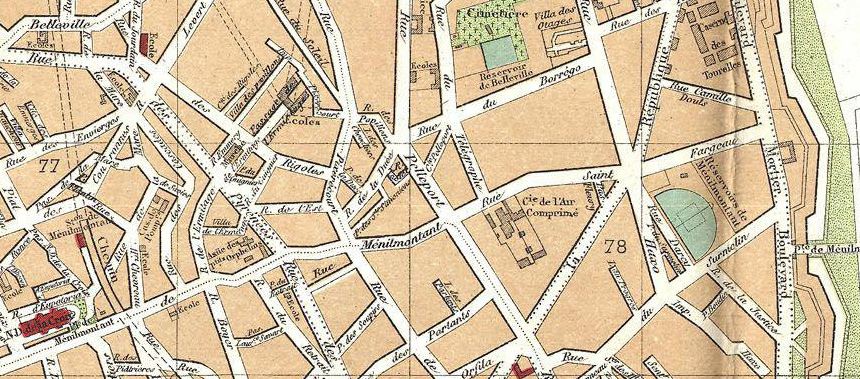 |
| Left: The location of the St-Fargeau usine in Belleville: 1892
The 'Cie de l'Air Comprime' site can be seen just to the right of centre, opposite the Rue de Telegraphe. This was the site of one of the Chappe optical telegraphs that linked Paris with distant places such as Lille and Strasbourg. This district is the highest ground in Paris, (apart from Montmartre) which is why the Menilmontant reservoir was sited there; it could supply water by gravity to the top floors of the buildings of Paris.
The factory buildings are accurately represented according to the plan just above.
The Thiers wall can be seen at extreme right, and the Petit Ceinture railway curving upwards at left, with no sign of a goods yard for coal.
From Paris map 1892
|
THE QUAI DE GARE USINE
By 1889 Popp's Compagnie Parisienne de l'Air Comprimé had 40 miles of pipelines supplying 4,000 establishments. The demand for compressed air was still growing, until the Saint-Fargeau usine became unable to meet it during peak periods. n response the usine at the Quai de Gare was built in 1891 with an output equivalent to 10,000 horsepower.
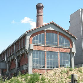 |
| Left: The Quai de Gare usine today, with its chimney
Only the main engine hall of the Quai de Gare remains today. It has been thoroughly renovated and is used as the library of an architecture school.
Being on right next to the Seine, the Quai de Gare usine suffered severely from the Great Flood of Paris in 1910. The clock network failed at 10:50am on the 21st of January 1910.
|
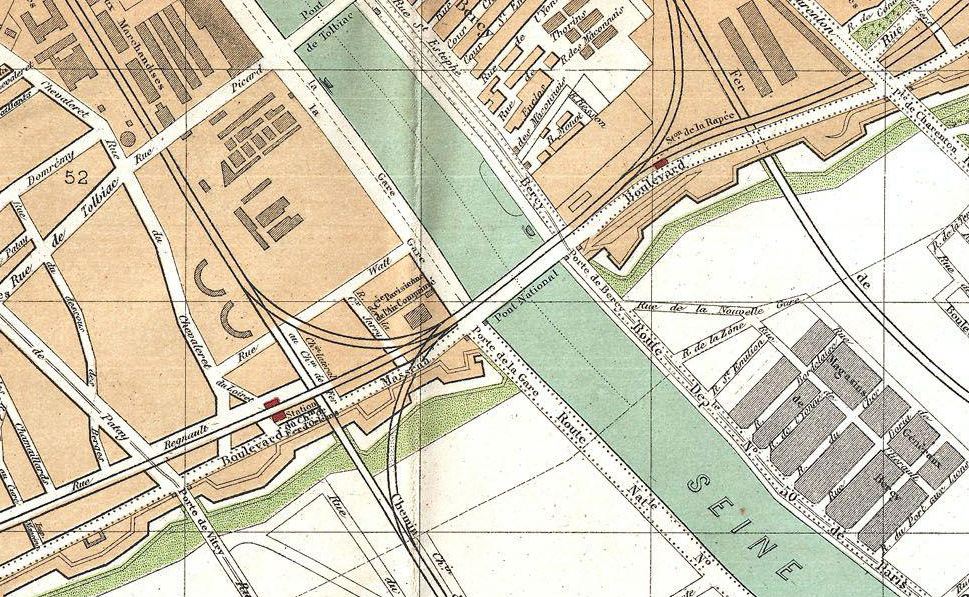 |
| Left: The location of the Quai de Gare usine
The usine can be seen at the left end of the bridge Pont National. It is clearly well-placed for drawing cooling water from the Seine, and the Petit Ceinture runs right past the factory, (from lower left to upper right) which presumably facilitated coal deliveries, though again no handy goods yard can be seen on this map.
Note the rail junctions to the Orleans line running from lower middle to upper right, where it terminated in the Embarcadere d'Orleans, a small station that was replaced by the Gare d'Orsay in 1900; this in turn closed in 1977 and the building converted to an art museum, the Musee d'Orsay. And a very fine museum it is too.
The railway line running from the right to top centre terminated at what became the Gare du Lyon.
From Paris map 1892
|
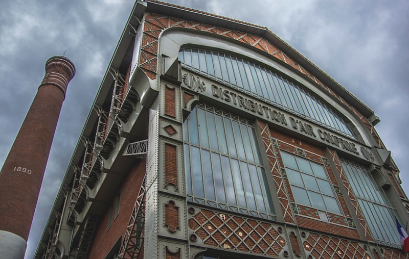 |
| Left: The other end of the Quai de Gare usine
Note the date of construction (well, perhaps start of construction) on the chimney.
|
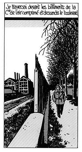 |
| Left: The Quai de Gare usine in fiction:
This is one of the illustrations for the graphic novel version of Brouillard au pont de Tolbiac. (Fog at Tolbiac Bridge) by Leo Malet, published in 1956. The graphic version was by Jacques Tardi in 1982. The chap here appears to be walking south-west away from the river, along the Boulevard Massena with its avenues of trees, leaving the usine behind him. The railway is presumably the Petit Ceinture, though only one of the two tracks is visible.
If anybody is interested, the pont de Tolbiac is a road bridge across the Seine, with its western end in the 13th Arrondisement of Paris, where most of the action of the novel takes place. It can be seen at the top of the 1892 map above.
|
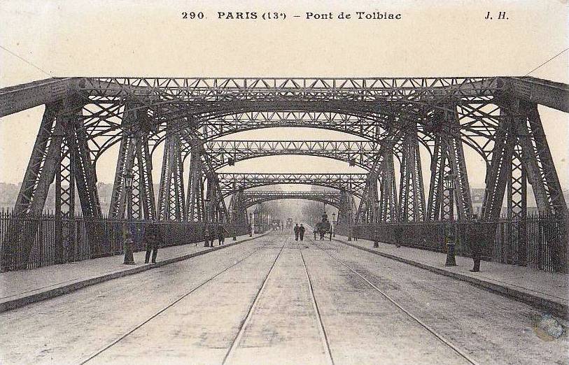 |
| Left: the Viaduc de Tolbiac, circa 1905
This is the Pont de Tolbiac so far as the novel above is concerned. It certainly looks as though just about anything could happen here.
Things are indeed a bit murky, for the postcard actually shows the Viaduc de Tolbiac, which carries the Rue Picard over the railway lines to the Gare d'Orsay, before it reaches the Pont de Tolbiac which is a stone arch bridge crossing the Seine. See map above.
The viaduc was built in 1895, and dismantled in 1996 to make way for a slab structure. Shame.
|
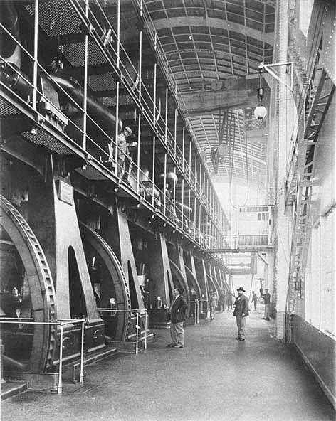 |
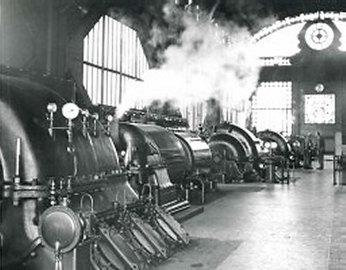
| Left: Inside the Quai de Gare usine: circa 1905
This shows the huge vertical steam engines, with the human figures giving the scale. Eight flywheels are visible here, so we are looking at one half of the engine hall.
In the centre of the picture there appears to be a chap hanging on to a crane hook in a most hazardous manner. Clearly no risk assessment has been performed.
|
 |
| Left: Section of the Quai de Gare usine: 1892
Here the two rows of boilers are in the middle, with the engine-house on the right.
- A = drying channels
(not sure what that means- they look like sewers in cross-section. May just mean 'drainage')
- C = water conduit
- E = water purifier (presumably water-softening)
- F = boiler
- G = travelling crane
- M = steam engine & compressor
- R = air reservoirs
- S = roof ventilator
- V = heaters (presumably boiler feed heaters)
From Ice & Refrigeration, Oct 1892
|
 |
| Left: Section of the Quai de Gare usine engine hall: 1892
The compressors were of the Cockerill type. Note the need for massive flywheels, as the power from the engine and the power used by the compressor were not distributed in the same way over a cycle. Air was delivered at 7 atmosperes (103 psi). In preparation for the operation of the new usine, new air pipes 20 inches in diameter were laid, connecting with the old pipes 12 inches in diameter.
- c = air compressor
- C = water tunnel
- F = boiler
- G = travelling crane
- h = high pressure steam cylinder
- S = roof ventilator
- t = air pipelines
- T = pipe tunnel
- T' = intermediate air reservoir
The obvious question is that since this is clearly a compound engine, where is the low-pressure cylinder?
From Ice & Refrigeration, Oct 1892
If you are wondering why a refrigeration journal should take an interest in a compressed-air usine, it is because the exhaust air from the air motors was cold, and was widely used for cooling and chilling.
|
 |
| Left: Plan of the Quai de Gare usine engine hall: 1892
This shows one half of the engine hall.
- c = compressor cylinder
- h = high pressure steam cylinder
- J = pumps (function unstated)
- L = filter wells
- R = air reservoirs
From Ice & Refrigeration, Oct 1892
|
By 1905 seventy workers were employed at the Quai de Gare usine night and day.
On 17th September 1905 at 8:15am the explosion of a 290 mm diameter steam trap working at 10 bar pressure
in the boiler hall killed three workers and injured three others. Pierre Héritier, a twenty-eight-year-old driver and Gustave Jaussonne, stoker, were killed instantly. Basile Rignault succumbed a few hours after to his wounds. Too badly scalded to be saved, two of the other wounded, Theophile Bernard and Eugene Allary, died the next day at the Hospital of the Pity bringing to five the number of fatalities.
 |
| Left: SUDAC steam turbines and centrifugal compressors at the Quai de Gare usine
The date of turbine installation has not so far been found.
Photo date unknown at present
|
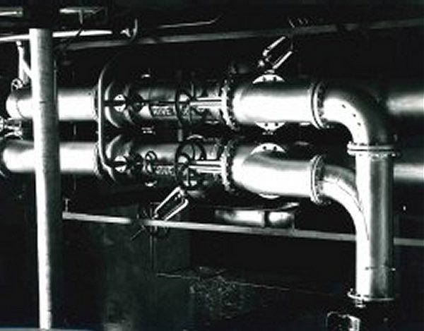 |
| Left: SUDAC supply pipes
The upper pipe is labelled 'rive gauche'. (left bank of the Seine)
The lower pipe is labelled 'rive droite'. (right bank of the Seine)
Judging by the welded junction at right, this is was a relatively modern part of the network.
|
USING THE COMPRESSED AIR
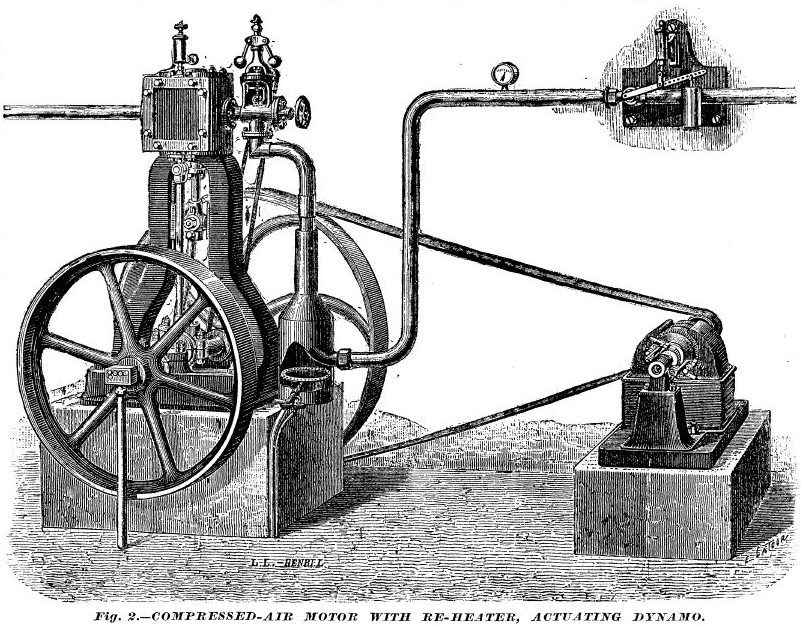 |
| Left: Air-motor system with gas reheater: 1889
This is a typical compressed-air installation for generating a modest amount of electricity; enough for one establishment. The air engine is indistinguishable from a steam engine, which it may have been at an earlier stage in its career; it has a conventional speed governor that works by throttling the incoming air.
The air enters the premises at the right, its delivery being controlled by valve controlled by a spring and a weight; this apparently functioned as a pressure regulator. From there the air passed into the reheater, where a gas-ring heated the air pipe. This extracted much more power from the air (which had lost its heat of compression) and also prevented the engine from freezing up. A small Gramme dynamo is driven by belt from the engine, much geared-up. It seems ironical that the compressed-air power system could not be used effectively unless gas was also available. Coke-fired reheaters could also be used but were much messier.
In some cases the amount of reheat was limited so that cold air came out of the engine, and this was used for cooling beer, general cold storage, making ice and ice cream, etc. However, the air always had some moisture content, and it was important to make sure that the engine did not choke with ice or snow.
One thing missing here seems to be a meter so the air used could be charged for; I would have expected something like a gas-meter. There seems to be a little box fixed to the axle of the engine; perhaps this was a revolution counter.
From The Manufacturer and Builder, August 1889, p183. Courtesy Tom Bates
|
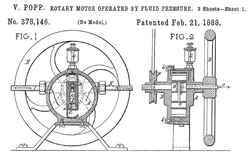 |
| Left: Popp air-motor from US patent 378,146: 1888
If you are researching the Paris air system, sooner or later you will come across a mention of the Popp rotary air engine. This has finally been tracked down by one of my correspondents. Popp was granted US patent 378,146 in Feb 1888.
In the long history of rotary steam engines, there were few if any successes. However a rotary air engine probably sounded like a better proposition as it did not work over the great temperature range of a steam engine, which caused all sorts of trouble with thermal expansion. There would be no condensate to get rid of, though there might be trouble with icing if the air was wet and no pre-heating was used.
Power is developed by the sliding vane rotating in an eccentric cylinder. The earliest steam version of this appears to be the Woodhouse engine of 1839.
|
The exhaust pipe is of the same diameter as the inlet pipe, which would not have helped to get the maximum work out of expanding the air.
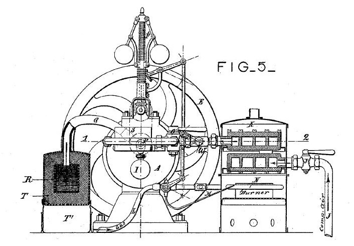 |
| Left: Popp air-motor system with gas preheater from US patent 378,146: 1888
This shows a fully equipped Popp engine. On the right is an air preheater K with a gas-burner N beneath it. The compressed air comes in at the right, through the stop-valve J and is heated by passing through the iron boxes. The gas-heater has a pilot light fed by small pipe M which bypasses the gas-control valve. The centrifugal governor appears to act on both the compressed-air supply and the gas supply to the burner for heating it, which makes sense.
The box S just visible above the central axle of the motor, is a revolution counter. The Popp patent does not say so, but this was presumably used to charge for the amount of air consumed.
The container R is a muffler (silencer) to reduce noise from the air exhaust. T and T' are not identified in the patent.
|
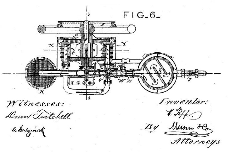 |
| Left: Popp air-motor system with gas preheater from US patent 378,146: 1888
The engine seen from above, showing at right one of the labyrinths in which the air was pre-heated.
The patent gives no indication of the size of the engine or how much power it would produce.
|
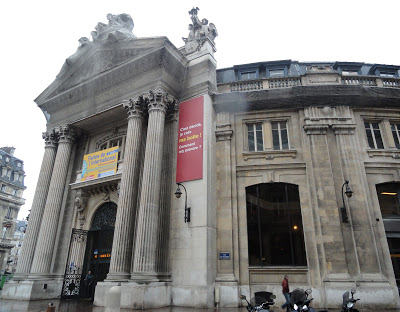 |
| Left: Electricity generation at the Bourse
The Bourse is a round building in the centre of Paris, on the Rue de Viarmes. It is next to Les Halles, an area which used to be the main produce market in the city. It was originally built as a corn exchange, then became a stock exchange, and is now a business centre. It is the Bourse de commerce, and not to be confused with the Paris Bourse which is a completely different building.
In 1889, during the conversion to a stock exchange, a 50 HP compressed-air lighting plant was installed in the basement, using Paxman engines; they illuminated both the Bourse itself and the surrounding areas. The cold exhaust air was used to chill cold stores also installed in the Bourse basement; these were rented out to merchants of Les Halles for the storage of fruit and vegetables.
|
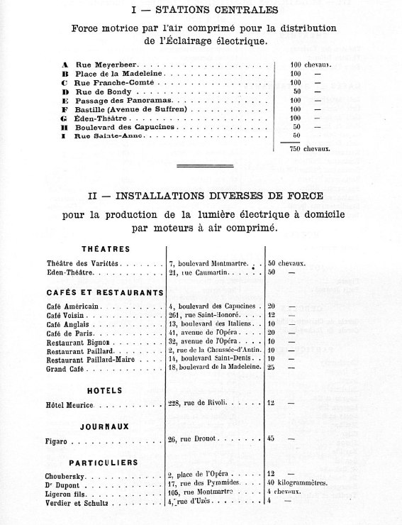 |
| Left: First page from 'Diverses Applications de L'Air Comprime et de Electricite' 1888
This is the first page from a 'Diverses Applications de L'Air Comprime et de Electricite' published by Popp, which lists the Paris air installations as of 1st October 1888. It lists the name and address of each user, and gives a unique insight into the wide variety of ways that the compressed-air supply was used.
In section I, each of the 'Stations Centrales' had a compressed-air engine driving an electrical generator for public supply; these were steam engines with some minor modifications. The total of 750 horsepower is equivalent to 560 kW. This may not seem much electric power for a city the size of Paris, but most of it was used for lighting rather than power. The Bourse station is not listed because it opened a year later in 1889.
Section II deals with compressed-air electricity generators for single enterprises; thus the Figaro newspaper had its own 45 horsepower (33 kW) engine. The Figaro manager wrote: "The service leaves nothing to be desired, and we only have to congratulate ourselves on daily reports with the administration of Mr. Victor Popp ". At least that's the version provided by Google Translate.
Particuliers translates as 'special'. What was special about these establishments is not currently known.
Note that the size of the establishment's installation is given either in chevaux or kilogrammetres, which was presumably an alternative unit of power usage.
|
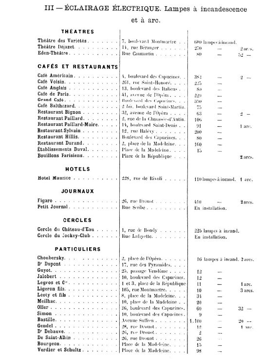 |
| Left: The second page from 'Diverses Applications de L'Air Comprime et de Electricite' 1888
This page deals with lighting, but it is expressed aa the number of incandescent and arc lamps used rather than horsepower.
Journaux are newspapers.
Cercle translates literally as 'circle', but actually means an exclusive gentleman's club;
the Jockey-Club is considered the most exclusive in France.
Particuliers again translates as 'special'. What on earth were they doing there? Whatever it was, they were it doing under electric light. It has been suggested that it simply refers to private houses, but 'Legros & Cie' sounds like a business to me.
|
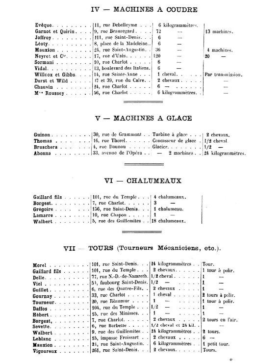 |
| Left: Third page from 'Diverses Applications de L'Air Comprime et de Electricite' 1888
Section IV of 'Diverses Applications' refers to powering sewing machines.
Section V deals with ice-making machinery; I am not sure what an 'ice turbine' is, but I suspect that an air-turbine was used to drive a compressor for ammonia refigeration. A concasseur de glace is an 'ice breaker' ie an ice-crusher.
Section VI is titled chalumeaux which translates as 'torches'; I assume this means industrial blowtorches.
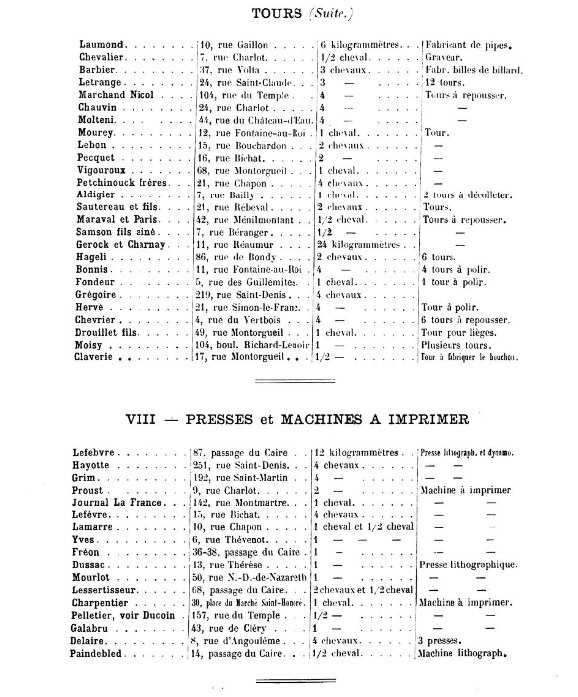
Section VII Tours does not translate directly, but I think it refers to lathes and turning.
|
 |
| Left: Fourth page from 'Diverses Applications de L'Air Comprime et de Electricite' 1888
Section VII of 'Diverses Applications' deals with the powering of printing presses.
|
 |
| Left: Fifth page from 'Diverses Applications de L'Air Comprime et de Electricite' 1888
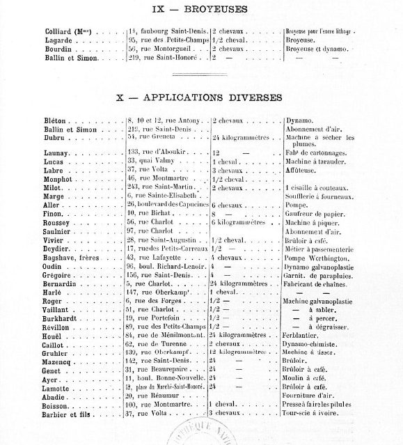
Section IX of 'Diverses Applications' deals with broyeuses which are shredders.
Section X gives us some really diverse applications, such as machine a piquer, which translates as 'stinging machine', (which leaves me quite baffled as to what was going on) and a feather-drying machine.
|
 |
| Left: Sixth page from 'Diverses Applications de L'Air Comprime et de Electricite' 1888
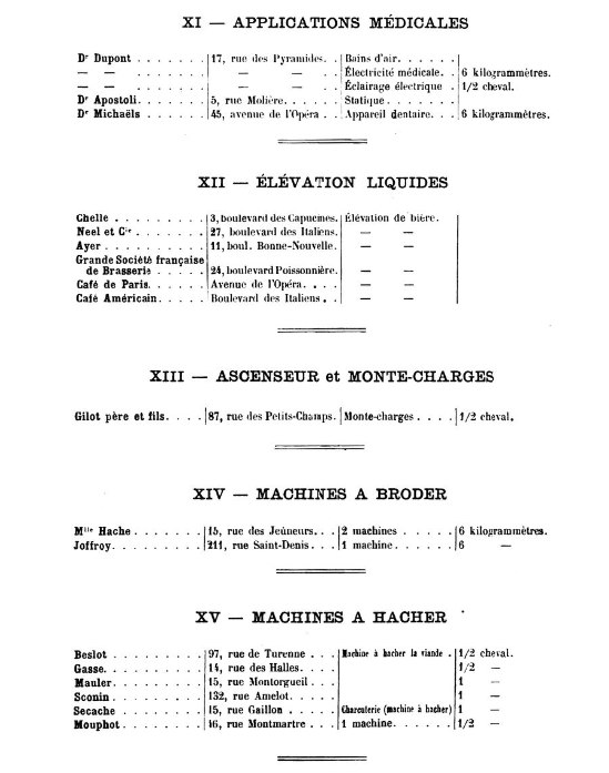
Section XI of 'Diverses Applications' deals with medical applications.
Section XII of 'Diverses Applications' deals with the elevation of liquids, in every case the liquid being beer. I thoroughly approve.
Section XIII deals with 'ascenseurs' which are lifts. 'Monte-charges' are, I think, goods lifts.
Section XIV deals with 'broder' or embroidery- presumably specialised sewing machines.
Section XV deals with 'hacher' or chopping up.
|
 |
| Left: Seventh page from 'Diverses Applications de L'Air Comprime et de Electricite' 1888
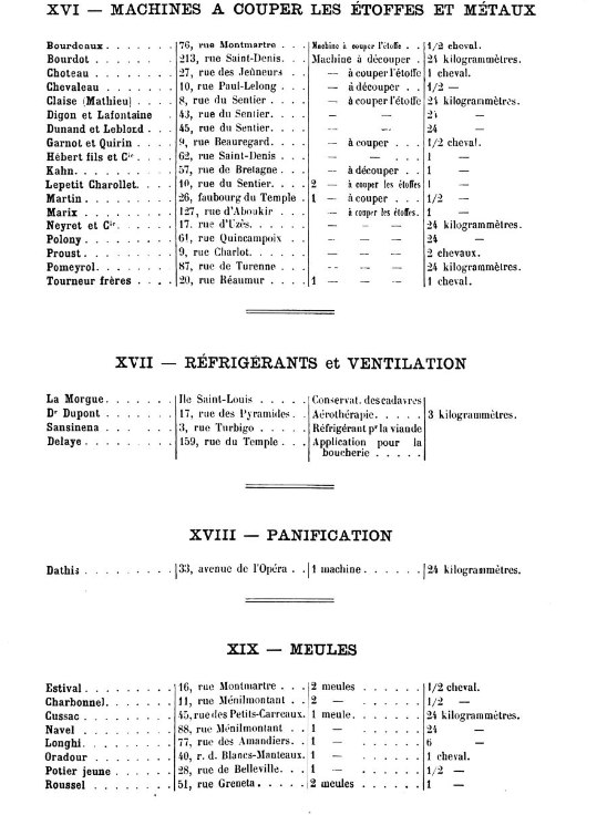
Section XVI: This is the cutting of fabrics and metals
Section XVII: A notable application here is the refrigeration of corpses at the Morgue on the Ile St-Louis.
Section XVIII: Panification is bread-making, as you probably guessed.
Section XIX: Meules are millstones, so these establishments were doing some sort of milling.
|
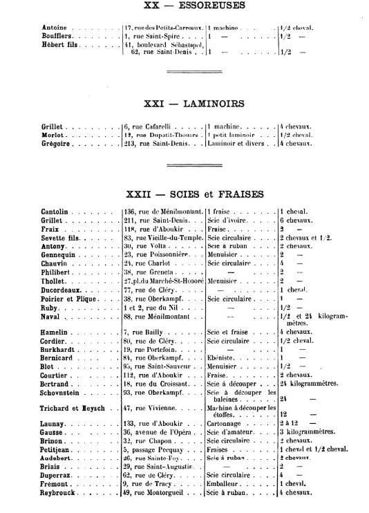 |
| Left: Eighth page from 'Diverses Applications de L'Air Comprime et de Electricite' 1888
Section XX deals with essoreuses which are wringers for drying cloth.
Section XXI deals with laminoirs which are rolling mills. Presumably not steel-rolling mills which require thousands of horsepower and were not likely to be found in the middle of Paris. It probably refers to the manufacture of linoleum, etc.
Section XXII deals with Scies et Fraises which literally translates as 'saws and strawberries' but a bit of Googlage suggests that in this case a fraise is a circular-saw blade.
|
LATER HISTORY
In 1949 CPAC became the Société Urbaine de Distribution d'Air Comprimé. (SUDAC)
SUDAC decided to build a third power station in Aubervilliers in 1959. It opened in 1961.
By the end of the 1960's the amount of industry in Paris was decreasing rapidly. The company still exists as SUDAC though it now supplies factory compressed-air plants; the first of these was installed in 1973.


