Gallery opened 27 Aug 2018
Updated: 20 Dec 2018
New suction motor example (turntables)
Pneumatic computing (sort of)


The Pianola |
Gallery opened 27 Aug 2018 |
This gallery of the museum is a direct result of my recent to Amsterdam. I did not want to accompany my companions to the Van Gogh Museum, so I took myself off to the Pianola Museum at 106 Westerstraat. And a very fine museum it is too, highly recommended. Hence this page.
I am NOT an expert on pianolas in general, so please let me know if I've got something wrong.
THE PIANOLA
The Pianola or player piano is a piano that plays automatically, with information on the note and its duration read from holes made in a moving paper roll. It has a normal keyboard and can be played by hand in the usual way. There is a Wikipedia page which is strong on the history of the pianola but says little about the technology.
Two good websites are The Player Piano and The Pianola Institute but both are light on technical information.
PIANOLA TECHNOLOGY
When I strode into the museum I was aware that the operation of a pianola is essentially pneumatic. Using my skills as an audio engineer, I deduced that the pedals drove the piano roll, and at the same time operated a peculiar-looking compressor next to the roll, which produced compressed air to operate the keys. I was totally and completely wrong.
The pianola is indeed primarily a pneumatic instrument, but it operates by suction (ie a partial vacuum) rather than positive air pressure. There is a good reason for this.
Just below is my attempt to explain the operation of a typical pianola; be aware there were many variations.
The pedals have no mechanical connection except to the bellows which create a pressure below atmospheric. This 'suction' is stored in the equaliser (or reservoir) which helps to keep the suction constant in the face of varying demands.
The holes in the tracker bar are usually covered by the paper roll, and there is a partial vacuum in the bottom section of the relay, keeping the valve pulled down. The relay diaphragm P is called a 'pouch' in pianola-speak; when a hole aligns with the tracker bar the suction below the diaphragm is released; there is still suction above it so the valve stem moves upward, letting suction through to the 'pneumatic' which operates the piano mechanism. 'Pneumatic' is presumably short for 'pneumatic motor'. Note (ha!) that the piano action is very much simplified in the diagram.
When the hole in the roll is no longer over the tracker bar, air no longer flows in and the air in the bottom section of the relay is sucked out through a bleed hole B and the valve moves down again, cutting off the suction to the pneumatic and opening it to the air through the top of the relay.
I believe that pianolas operate by suction rather than pressure because it keeps the piano roll sucked against the tracker bar, making a good seal. Pressure would tend to force the roll away from the tracker bar, and if that happened all the notes would sound at once. Probably not a good idea.
 | Left: Basic mechanism of a Pianola
|
We now come to what I find the most interesting part. The piano roll need to be moved steadily over the tracker bar, and driving straight from the pedals would not give steady motion or a set speed. Therefore the take-up roller for the piano roll is actually driven by a pneumatic motor to make it independent of pedalling speed. This is what I thought was a compressor; in pianola-speak it is usually called the 'air motor'. It is very unusual to find a motor or engine working off suction rather than pressure- one reason is that since you can only have a maximum of 14.5 psi of suction (ie a perfect vacuum) you're not going to get much power out; compare a steam engine running at 250 psi.
I said when I set up this page, that it was the only example of a suction motor that I knew of; Googling 'suction motor' just gets you lots of suction pumps driven by electric motors. However several people have pointed out that another, and more common example, is the vacuum-operated motors that used to be fitted to drive motor-car windscreen wipers; the vacuum was derived from the engine induction manifold. This is described in Wikipedia, and there is a specialised site here that gives much more detail.
The great snag with vacuum-operated wipers is that the amount of vacuum or suction in the manifold is not constant; it is greatest when the engine is idling with the throttle closed, and weak with the throttle full-open. This is of course quite the wrong way round from the point of view of wiper operation; as you speed up to overtake the wipers slow down or stop, which is not exactly a safe situation. Vacuum-operated wipers have therefore been obsolete for many years.
There is another example of a suction engine. In the UK they were commonly used to power railway turntables, using vacuum created by a steam locomotive's vacuum brake ejector.
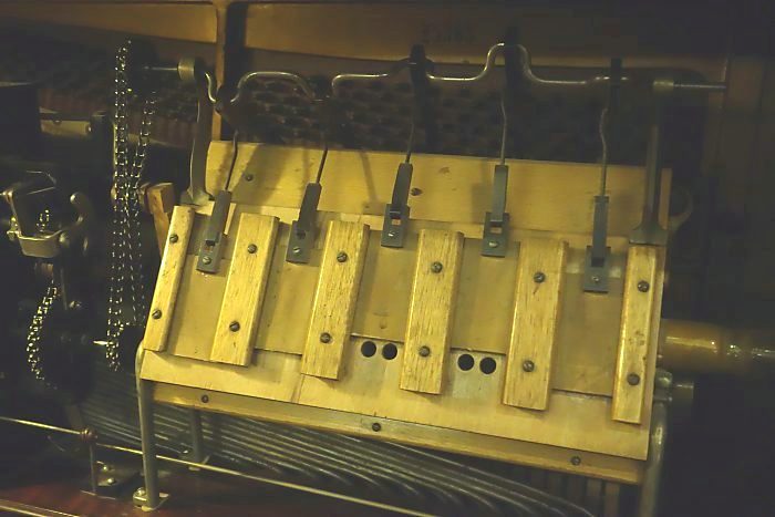
The pianola air motor is composed of pneumatics (bellows) rather than pistons in cylinders, as is every motor in the system. This may seem merely quaint, but my interpretation of this is that it is highly practical. There is no need for lubrication, very little friction, and it's generally a low-tech approach that does not rely on close tolerances. There is no or very little leakage, so a pianola does not sit there hissing like a nest of serpents. The air-motors I have seen have been 3-phase or 5-phase, to give a steady torque on the piano roll mechanism.
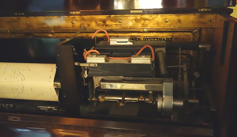
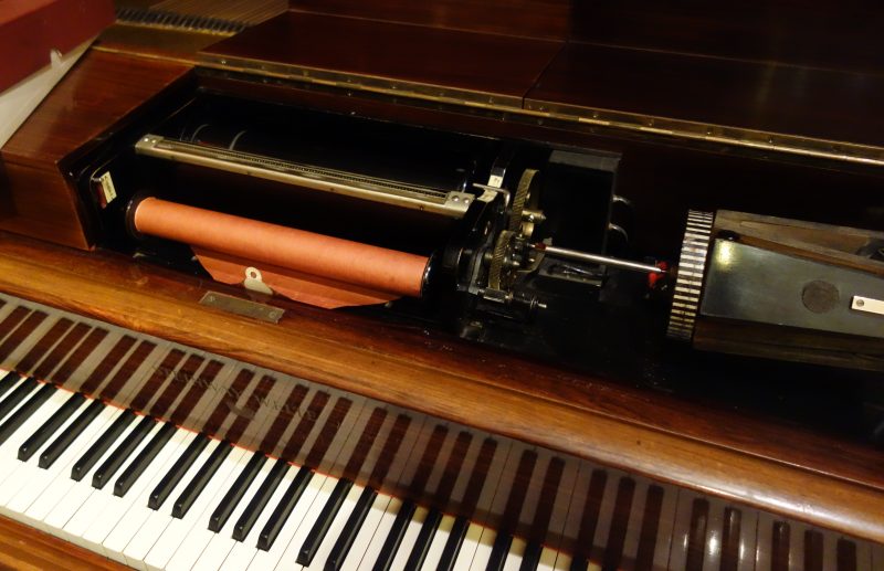 | Left: Pianola tracker bar and air motor
|
A bellows used to compress air merely needs automatic non-return valves for induction and delivery. An air motor, on the other hand requires positively operated valvegear to alternately apply suction and then admit air.
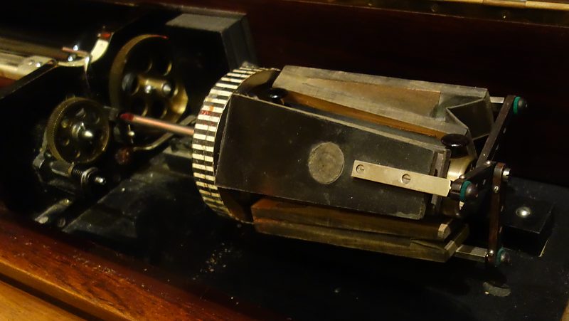 | Left: Three-phase air motor of above pianola
|
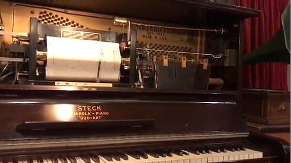 | Left: Still from Steck pianola video showing three-phase air motor on the right
|
 | Left: Another pianola with a three-phase air motor on the right of the piano roll
|
 | Left: Five-phase air motor
|
![]()
![]()

|