Updated: 11 Dec 2014
Walker engine added
This gallery is in course of arrangement


Rotary Internal-Combustion Engines |
Updated: 11 Dec 2014 |
Rotary internal-combustion engine proposals exist in their hundreds, if not their thousands. The similarity with the rotary steam engine in the past is hard to ignore, the difference being of course that in this case a rotary engine achieved some success, in the shape of the Wankel , even if if it took a huge amount of development to get there.
If you have looked at my page on rotary steam engines, you will know that even with steam the problems of sealing and efficiency were severe. Things must surely be an order more difficult in a rotary internal combustion engine, where the pressures and temperatures are much higher.
This page used to contain other engines that were not strictly rotary designs, such as toroidal engines and The Scissor, pursuing-piston, or cat-and-mouse engines. These have now been moved to their own pages in the interest of faster downloads. See the Unusual IC Engines page for a full list.
This web page does not even attempt to provide a comprehensive list of the many rotary internal combustion designs that were promoted, as there are simply too many of them. The dates given here are not necessarily the date on which the proposal was made public, the patent was filed, or anything else precise. It simply means that the project was being actively developed and promoted at that time.
If you know of any good rotary IC engines that should be here, please let me know...
The list below links you to details of the engine, where such details exist on the page. It does not pretend to be a complete list. More engines will be added in time, but probably rather slowly. You know how it is. Of course you do.
Please ignore the #-numbers, this is just a filing system that attempts to keep all this organised. The greyed-out engines have not yet been delivered to the Museum.
THE WEBB ENGINE: 1853
Originator: Joseph Webb (of Dalston, in the county of Middlesex, England) British Patent No 1216, 1853.
 | Left: The Webb engine: 1853
|
The combustion gases were presumably generated in some sort of pressurised external burner, but the Museum has currently no information on this, or on what fuel was proposed. Webb's patent application never got beyond the provisional stage, and there is no indication the engine was ever built.
Nice drawing, though.
1.gif) | Left: Animation of The Webb engine: 1853
|
THE CORNU ENGINE: 1898
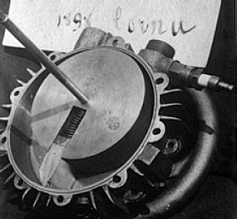 | Originator: Paul Cornu (1881�1944)Paul Cornu is much better known as a pioneer of the helicopter, though it is generally accepted he made no controlled flights; see Wikipedia. Little is known about this engine, built by Paul and his father Jules, but Leishmann and Johnson, in their paper "Engineering Analysis of the 1907 Cornu Helicopter" state that it would run unloaded but stopped immediately when it was asked to produce any power. See also: Cornu F, "Un pionnier de L�helicoptere: Paul Cornu (1881�1944)", Imp. Moriere, Lisieux, 1969. This engine has a single sliding vane set in the piston (rather surprisingly, there is nothing that exactly corresponds to it in the Rotary Steam Engine Gallery) It looks like a rather crude production; that wonky spring pushing the vane outwards does not inspire confidence. |
THE JASPER EXPLOSIVE MOTOR: 1899
Originator: Wilhelm Jasper (New York)
The Jasper Explosive Motor (clearly not a prime mover for the nervous) used the same mechanical principles as the Behrens rotary steam engine and one can only speculate as to how Mr Behrens felt about this.
The holes 9 are "ignition inlets" and burners were maintained just outside these apertures. The sector plates 15 uncovered the ignition inlets and the inlet ports 4 at the appropriate times. The exhaust port is at 22. The engine was water-cooled, with cast water passages such as 27.
Currently nothing is known as to whether this engine was ever built and if so, what the results were. As Bill Todd pointed out to me, it's an inherently inefficient non-Otto cycle engine, as it has no charge compression at all.
THE UMPLEBY ENGINE: 1908
Originator: Umpleby (England)
 | Left: The Umpleby engine: 1908
|
THE WANKEL ENGINE: 1957
Originator: Felix Wankel (Germany)
![]()
 | Left: The Wankel engine: 1957
|
![]()
THE SARICH ORBITAL ENGINE: 1972
Originator: Ralph Sarich (Perth, Australia)
This design gathered a lot of publicity in its day; See Wikipedia.
The Sarich Orbital engine had a number of fundamental and unsolved problems kept it from becoming a practical engine. Amongst these are key components that cannot be cooled and others that cannot readily be lubricated; it is very susceptible to overheating. To which we might add the usual sealing problems.
See United States Patent 4,037,997, "Orbital Engine With Stabilizing Plate", published 1977
THE CHAPMAN ORBITAL ENGINE: 1973
Originator: Howard R Chapman (California, USA)
This engine should not strictly be in this gallery of the museum as it was not an IC engine, though it was closely associated with them; it was a "steam engine" powered by Freon. It was intended as part of a bottoming cycle to improve the efficiency of conventional IC engines.
Since it is fundamentally a steam engine, it is to be found in the Rotary Steam Engine gallery, here.
See United States Patent 3,743,451, "Rotary Engine", published 1973
THE SIDDONS S-ENGINE
![]()
![]()
UNCLASSIFIED
 | Left: The Siddons S-engine: 1969
|
THE HAMILTON WALKER ROTARY ENGINES
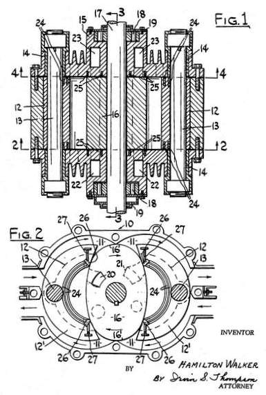 | Left: Hamilton Walker engine: 1965
|
 | Left: Hamilton Walker engine: 1965
|
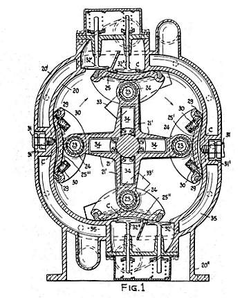 | Left: Walker engine: 1967
|
 | Left: Walker two-stroke engine: 1984
|
CURRENT ROTARY IC ENGINE ACTIVITY.
These are external links; not responsible for the content of external sites. Some of these links are currently dead but are retained here as their titles are the only clue to tracking them down if they reappear at another address, as they sometimes do.
The Janova Engine. The University of Arizona has rearranged its website.
The Ball Piston Engine. Dead link
The Rand Cam Engine. Back from the dead! Now called the Radmax (TM)
The Antonio Sanchez Hybrid Engine (Spain) Now dead as well.
The Dyna-Cam Engine Dead link
The Perlex Engine Dead link
The Veselovsky rotary engine Looks like this one's died too.
The Rotary of Koushi Akasaka (Japan)
SOME PATENTS
A huge number of patents for rotary IC engines have been registered. Here is a random sample.
US 2 927 560 Yves L. G. Brelle 1956
US 2 958 312 Shimomura Kenji 1957
US 3 186 385 Walker 1965
US 3 442 257 Walker 1967
US 3 743 451 Chapman 1973
US 4 037 997 Sarich 1977
US 4 434 757 Walker 1984

|