Steam engines have been designed and built with a wide variety of valvegear, but as far as is known at present, rotary valves have rarely been used. Some rotary steam engine designs made use of rotary valves, such as The Ritter Rotary Engine. They are not duplicated here.
Since the Museum has galleries on rotary steam engines, rotary IC engines and rotary-valve IC engines, a gallery on rotary-valve steam engines seems necessary to complete the set.
There are some rotary-valve steam engines in other galleries of the Museum:
The Paget Locomotive had rotary valves with a sleeve to control admission cutoff. Trouble with thermal expansion and valve seizure doomed this innovative locomotive. Valve drive was by a complicated system of cranks and shafts that included a gearbox to allow reversing.
The Carel engine was a high-speed stationary engine with rotary valves between two vertical sets of tandem-compound cylinders. Valve drive was by a bevel gear from the centre of the crankshaft.
The Corliss valve is sometimes called a rotary valve, though in reality it does not rotate continuously but oscillates back and forth; it is more correctly called an oscillatory or semi-rotary valve. This raises an interesting question. Corliss valves and the like (such as the engine of the First Heilmann locomotive) have much the same geometry as true rotary valves and would appear to have the same sealing problems. However, if this is the case it did not stop Corliss valves being widely adopted.
So why were rotary valves so rare? Perhaps the answer is simply that they posed more difficult sealing problems than conventional valves. Such problems sealed the fate of rotary steam engines, probably because their geometry turned an essentially 1-dimensional problem into a much more difficult 3-dimensional one. See here.

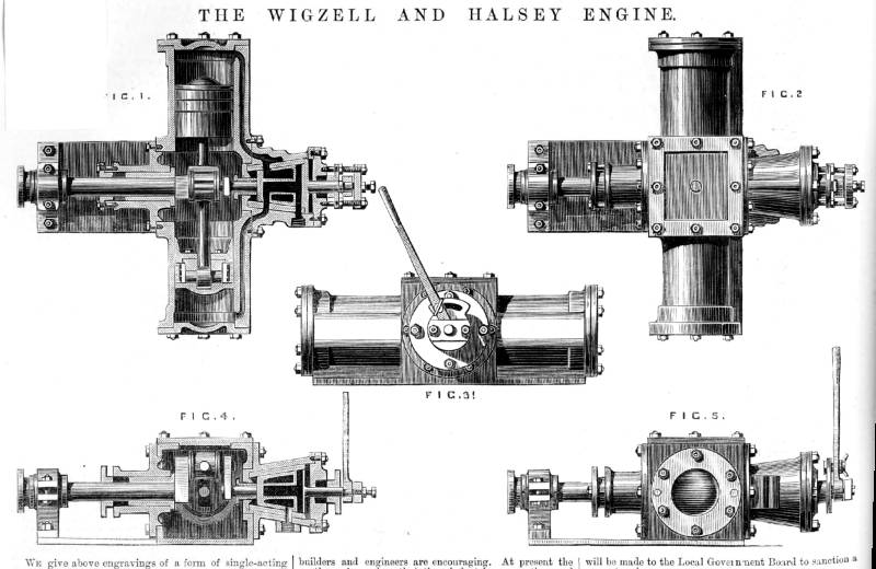
THE WIGZELL & HALSEY ROTARY VALVE STEAM ENGINE: 1877
 |
|
Above: The Wigzell & Halsey rotary valve engine: 1877. From Engineering 5th Jan 1877
This seems like a relatively conventional opposed two-cylinder engine apart from the rotary valve. This is made conical so axial pressure would hold it in against its bearing surfaces, with any wear taken up automatically; how well this worked I cannot say. It is not clear how this pressue was applied- probably by the incoming steam. A control valve concentric with the steam distribution valve allowed reversing- essential for what was intended for steam-launch use. According to the text three-cylinder versions were also being made.
The steam seems to go in and out of each cylinder through the same long and tortuous passage, which will not have helped efficiency as the incoming steam has to pass through a passage just cooled by the exhaust steam. Steam inlet and exhaust connections are on the side and bottom of the valve body.
|
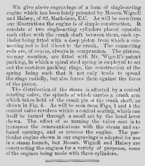 |
| Left: The Wigzell & Halsey rotary valve engine: 1877.
Description of the Wigzell & Halsey rotary valve engine in the British journal Engineering 5th Jan 1877
|
THE NOBLE ROTARY VALVE STEAM ENGINE: 1890
 |
| Left: The Noble rotary valve engine: 1890
The Noble Engine rotary valve engine depicted in the British journal Engineering June 20th, 1890.
Steam inlet and exhaust was controlled by means of a rotating disc with cut-outs, mounted at the end of the cylinder. In the engine shown there were two double-acting cylinders, and there valve-discs were driven by a common pinion mounted on a shaft driven from the crankshaft by bevel gears. Reversing (and cut-off control?) is accomplished by a lever that moves a sliding collar on the valve drive-shaft; this presumably alters the phase relationship between the crankshaft and the valve-discs by means of helical grooves in the valve drive shaft.
The three small cocks on the top of the cylinder are presumably for lubrication. I am inclined to think that forced lubrication would have worked better.
From Engineering June 20th, 1890
|
 |
| Left: The Noble rotary valve discs: 1890.
Since the valve-disc is at one end of a double-acting cylinder, getting steam in and out of the end of the cylinder remote from the cylinder-head requires long and convoluted steam passages running the length if the cylinder. This is very likely to have impaired efficiency.
Note the pipe for balance steam. The valve discs are of considerable area and the steam pressing them against their bearing would cause considerable friction. The balance pipe therefore routes steam to the opposite side of the valve-disc, to balnce the pressure. Since I would have thought that the steam pressure on different sectors of the valve-discs would be different, the balancing was presumably something of a compromise. The source of the balance steam is not clear.
From Engineering June 20th, 1890
|
 |
|  |
| Left: The Noble rotary valve engine: 1890.
|
THE DINGLER'SCHE ROTARY VALVE STEAM ENGINE: 1885
This single-cylinder double-acting rotary-valve steam engine was found in the Deutschmuseum in Munich.
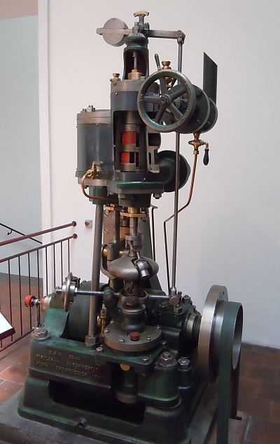 | |
| Left: The Dingler'sche rotary valve engine: 1885
The steam cylinder is on the left; in the centre is the valve chest with the rotating valves painted red. Below it is a thing like a flat metal pumpkin that is actually the centrifugal governor. The valve and governor shaft is rotated by a helical gear on the crankshaft. When the speed rises the governor weights lift and their motion is communicated to the top of the valve chest by the long vertical rod, and presumably controls the admission cut-off. The handwheel to the left of the governor is the speed adjustment, the big handwheel at top right is the steam stop valve.
The engine was intended for driving electrical generators directly and is therefore a high-speed steam engine. The operating pressure was 8.5 Bar (123psi) and 20 HP at 700 rpm was produced. The piston is 240mm in diameter but the stroke only 150mm, these very over-square dimensions being adapted for high speed. Date of manufacture unknown, but it was in operation until 1920.
Patentschrift 32,144 was issued on 14 July 1885, to Dinglersche Maschinenfabrik in Zweibrucken, which is the name on the left of the baseplate.
The engine cannot be steamed (as half the valve chest has been cut away) but it can be driven by the green drive-belt at the extreme right.
|
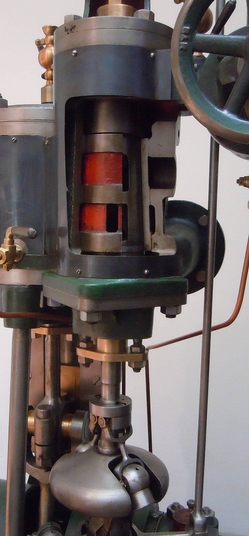 | |
| Left: The Dingler'sche rotary valve engine: 1885
A close-up of the rotary valve assembly, with the governor below.
I understand that 'Dingler'sche' means 'Dingler's machine'. The company was founded by Christian Dingler. There is a comprehensive website about the company here but it is all in German. The company built steam engines from 1873 to 1939.
|
THE READING ROTARY VALVE STEAM CARRIAGE ENGINE: 1902
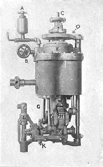 |
| Left: The Reading Steam Carriage engine: 1902
This compact and ingenious engine powered the Reading Steam Carriage. It has four single-acting cylinders arranged in parallel, driving two crankshafts that were geared to the output shaft. A salient feature is the single rotary valve which handles inlet and exhaust for all four cylinders. It sits on top of the cylinder block, and is driven by a vertical shaft geared to the output shaft. It was rated at 5.75 horsepower, not a generous power output. In use the cylinders were lagged and the gears and cranks were enclosed in an oil-bath.
- A Lubricator
- B Steam inlet & auxiliary throttle (to be closed and the handwheel removed when leaving the vehicle)
- C Reversing bell-crank
- E Steam chest
- L Cam-operated water pump
The vehicle was advertised as having a "four-cylinder single-acting engine. One rotary valve, requiring no packing." There was chain drive to the centre of the rear axle; apparently no differential was fitted.
Reading steam cars were built by the Meteor Engineering Company from 1902 to 1903,
after the company acquired the Steam Vehicle Company of America. The clearly short-lived Meteor enterprise is listed in Wikipedia, along with a surprisingly large number of other steam-car companies.
Image source: Steam Vehicle Company of America trade catalogue
|
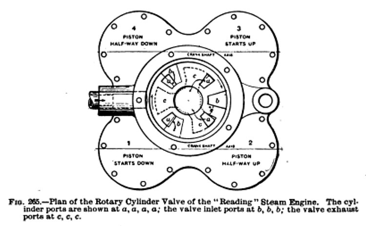 |
| Left: The Reading Steam Carriage engine: 1902
Top view of the cylinder block and valve housing.
Source Self-Propelled Vehicles by James E Homans. (pub Audel 1903)
|
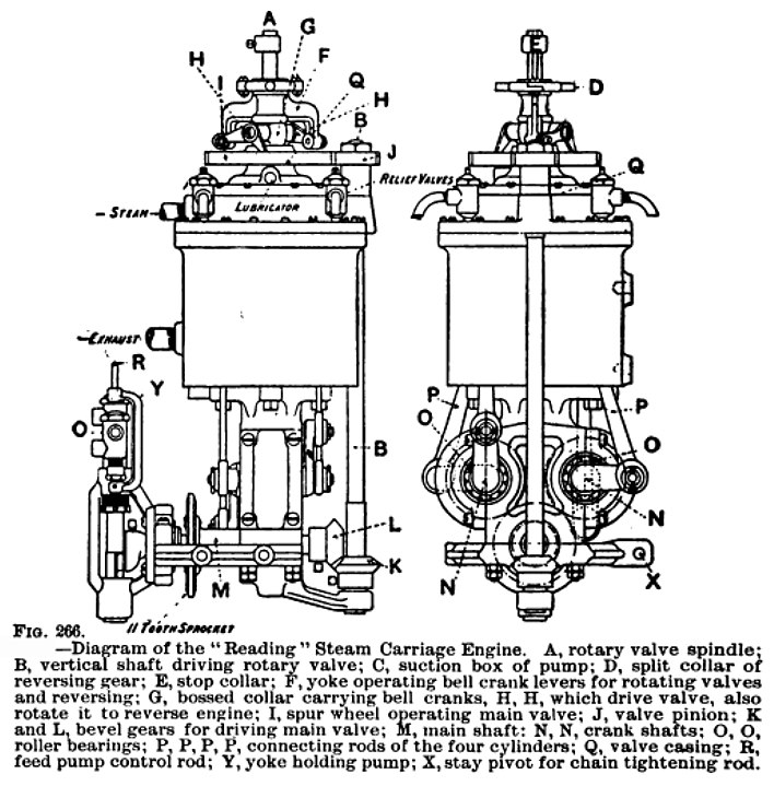 |
| Left: The Reading Steam Carriage engine: 1902
The vertical shaft B takes the drive from the crankshaft to the large gear driving the valve plate. The arrangements on the top of the engine are for reversing; whether it could also give a variable cutoff is not currently known.
Note the relief valves (presumably spring-loaded) to release condensed water on the top of the pistons.
Source Self-Propelled Vehicles by James E Homans. (pub Audel 1903)
|
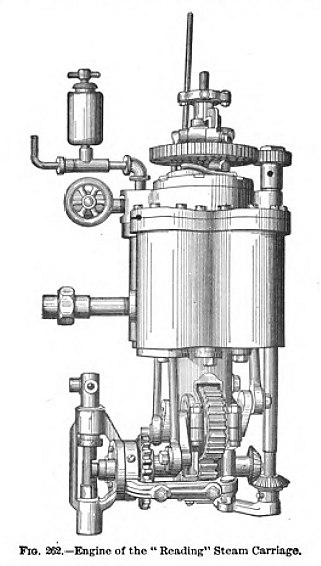 |
| Left: The Reading Steam Carriage engine: 1902
This engraving is clearly taken from the photograph above, and it gives a better view of the gearing and the drive to the valve.
Image source: unknown
|


