Gallery opened 18 Apr 2018
Updated: 23 Oct 2022
German refrig illustration added
Distributing cold under the streets


Refrigeration Networks |
Gallery opened 18 Apr 2018 |
Refrigeration may not be a glamourous area of technology but it is of vital economic importance. On the large scale it means frozen food can be transported around the world; on the small scale it means we don't have to go shopping for perishable food every other day.
There have been networks for distributing power by compressed air, and by high-pressure water. The time has been distributed by compressed air in Paris and in Vienna. However the distribution of cold around a town is something rarely discussed. Nonetheless it happened.
THE DENVER and ST LOUIS REFRIGERATION NETWORKS
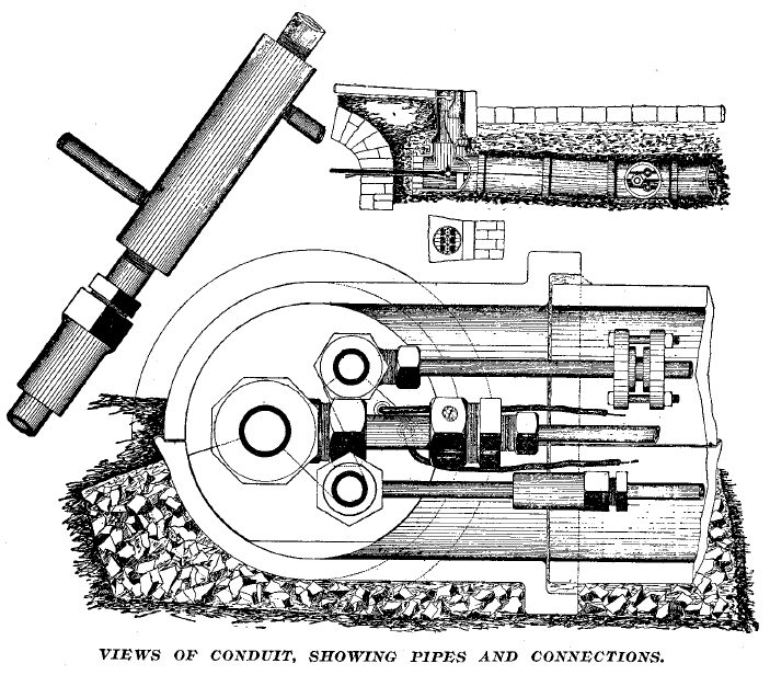
The pipeline system of the St Louis Automatic Supply Co was begun in 1890 and afterward gradually extended. It consisted of three lines of wrought-iron piping, inside a conduit of vitrified pipe. The pipes were "of extra-strong wrought iron, carefully put together with special fittings made of steel, and with carefully packed joints, so that leakage is rendered absolutely impossible." One devoutly hopes so.
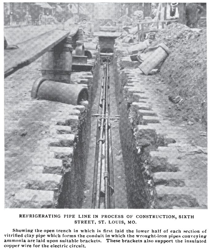 | Left: St Louis Automatic Supply Co refrigeration pipeline under construction
|
 | Left: St Louis Automatic Supply Co: 1894
|
All info from Ice & Refrigeration March 1894
THE KANSAS CITY REFRIGERATION NETWORK: THE MERCHANTS' REFRIGERATING COMPANY
All info on this network comes from COLD STORAGE AND ICE TRADE JOURNAL, September 1907
The Merchants' Refrigerating Company was organized by J E Brady, its president and manager, in 1903, together with six other produce dealers. A plot of ground at 550 and 552 Walnut street was bought and Warehouse A erected there. At the same time the warehouse was being planned Brady became convinced that a street pipe refrigerating system which would bring all the conveniences of a cold store to the very door of every produce dealer in that section of Kansas City would be a great success. There were many difficulties to overcome, but finally the pipes were laid and-the service inaugurated. It was an instant success, for not only the produce dealers along the route of the pipe line, which was about a mile in extent,but the hotels, florists, druggists and other business men using large quantities of ice in the main business section of the city, demanded that the service be extended to their establishments.
Warehouse A was built of brick, four stories high, and contained ten rooms, with a total storage capacity of 400.000 cubic feet. It was equipped with two 75 ton Wolf Linde type ammonia compression refrigerating-machines, powered by steam engines fed by boilers fired with crude oil on the 'Roop & Johnson' system.
 | |
Above: The Kansas City refrigeration network in 1907. A= Warehouse A, B= Warehouse B, C= Central Power Plant (top right)
|
The demand for refrigeration increased, and in autumn 1906 work was begun on Warehouse B and the Central Power Plant, both on West Third street, directly opposite each other. The location chosen for the new works was in the heart of the produce business district. The growth of demand had been so rapid that a Central Power Station as well as Warehouse B was needed. The Central power station was separate from the new Warehouse B but connected to it by a passageway under the street. Central power station contained all the machinery for both Warehouse B and the distributing pipeline.
Refrigeration was distributed in the form of liquid ammonia under pressure in a first pipe; assuming it worked on a normal ammonia cycle, the pressure here would have been 150 to 170 psi. When the pressure was released in a throttling valve, the ammonia vapourised and became very cold due to the latent heat of vapourisation. The vapour was then returned to the central station in a second pipe. There was a third pipe used for pumping ammonia out of refrigerating establishments or isolated pipe sections that required maintenance.
Note that all the pipes were at ambient temperature, the cold not being produced until the ammonia had reached its destination; there was thus no need for insulation or lagging.
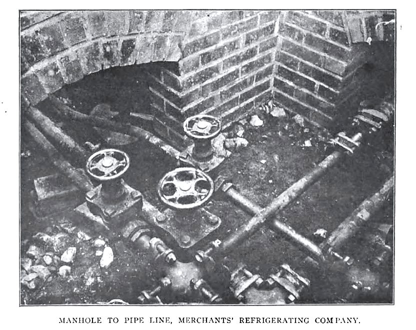 | Left: Kansas City refrigeration manhole in 1907.
|
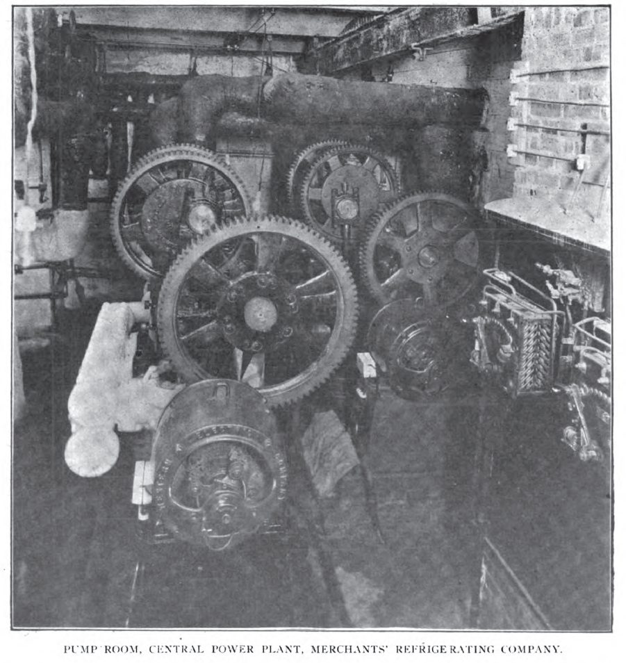
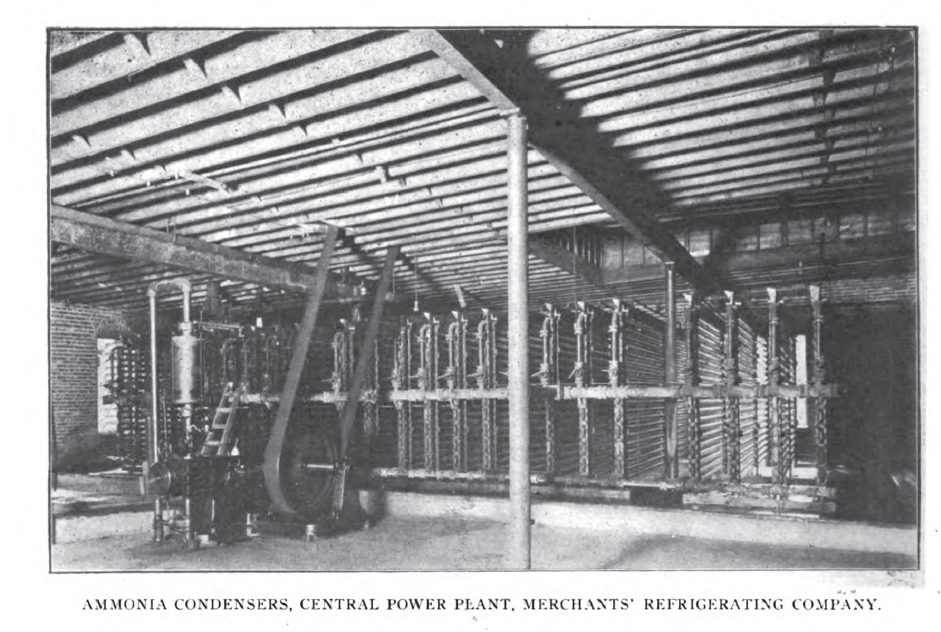 | Left: Merchants' Refrigerating Company Central Power Plant: 1907.
|
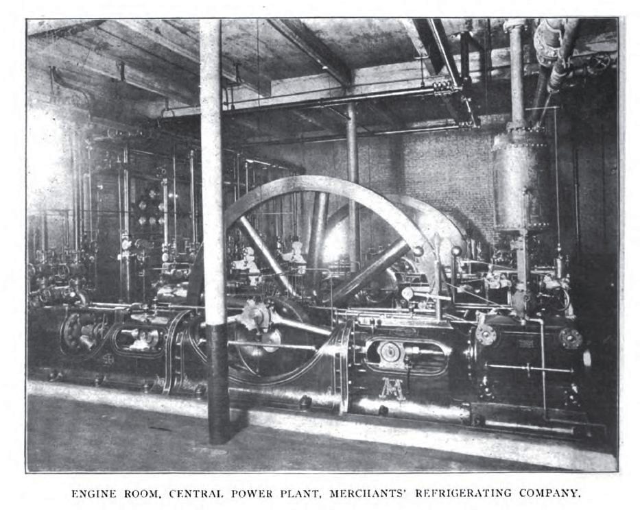 | Left: Merchants' Refrigerating Company Central Power Plant: 1907.
|
 | Left: Merchants' Refrigerating Company Warehouse A plant: 1907.
|
 | Left: Merchants' Refrigerating Company Warehouse A plant: 1907.
|
In 1907, the Kansas City network was said in the COLD STORAGE AND ICE TRADE JOURNAL article to have been in successful operation for four years, which seems to indicate there were no unfortunate accidents that filled the streets with choking clouds of ammonia.
When I first heard of these refrigerating networks, I have to say my first thought was- running high-pressure ammonia pipes under the city streets? What could possibly go wrong?
However, I have to say that searching for 'ammonia accidents', while bringing up plenty of contemporary disasters, has not so far found anything at this sort of date.
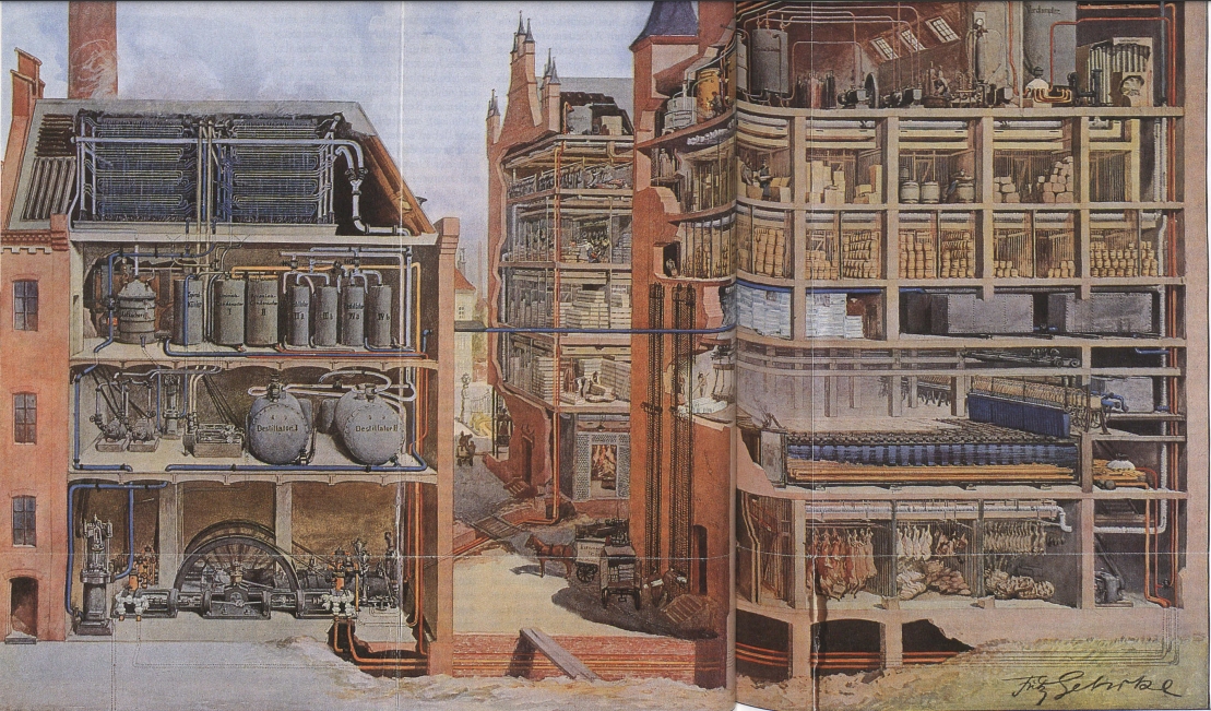 | |
Above: German Refrigerating company plant & warehouses
|
![]()

|