This page is now titled "British & Swiss Vertical Boiler Locomotives" as a separate page for French vertical boilers has been created.
Many steam locomotives have been built with vertical boilers, though horizontal boilers are greatly in the majority. A vertical boiler allowed a locomotive to be built on a short and narrow wheelbase, allowing it to negotiate the tight curves and narrow gauge tracks typically found in industrial railways. Maintenance is easier because a vertical boiler can be simply lifted off the chassis for replacement, while horizontal boilers are much more an integral part of the locomotive.
A major advantage of the vertical boiler is that it is much less sensitive to being tilted on inclined track; with a horizontal boiler an incline could lead to the firebox becoming uncovered, with disastrous consequences.
A disadvantage is that the size of a boiler is limited by height restrictions. Other limitations are restricted grate area and relatively short boiler tubes.

CHAPLIN LOCOMOTIVES
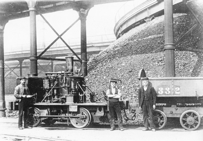 |
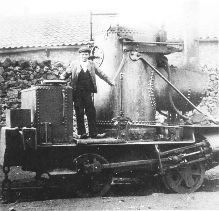
| Left: Chaplin vertical-boiler locomotive at Beckton gasworks: early 1900's
This is one of three locomotives built by Alexander Chaplin & co, delivered in 1874 to Beckton Gasworks east of London, which were variously described as "The largest gasworks in Europe" or "The largest gasworks in the world". They had two vertical cylinders that appear to have been geared to one of the driving axles.
They worked trains removing coke from the Beckton retort houses; they were numbered 1675, 1756, and 1757. Little information is available on these engines; it is believed that all were scrapped around 1900.
Here are some nuggets of hard fact:
Track gaugeTBA
Wheel diamTBA
CylindersTwo vertical , 5.75in diam x 11in stroke
Working pressure100 lb/sqin
| | | | | | | |
|
In the background can be seen part of the Elevated Railway that delivered coal to the retort houses.
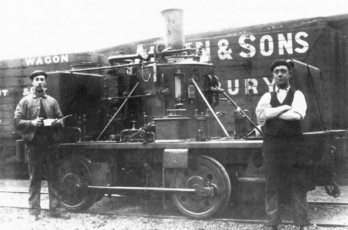 |
| Left: Chaplin vertical-boiler locomotive at Beckton gasworks: early 1900's
Another view of the Chaplin locomotive. It is believed that the left axle, under rhe water tank, was chain-driven from a sprocket on the engine crankshaft, but this is not yet confirmed.
|
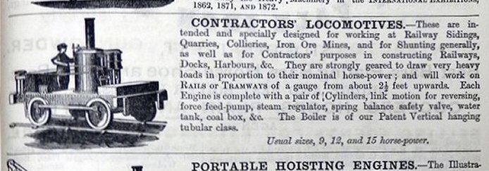 |
| Left: Advertisment for Chaplin vertical-boiler locomotives: 1881
Alexander Chaplin & Co of Cranstonhill Engine works, Port Street, Anderson, Glasgow were makers of locomotives, road engines, boilers and stationary engines, though cranes seem to have been their major interest. They began operations in 1849 and ceased manufacturing in 1930.
A total of 135 of these locomotives were built between 1860 and 1899.
|
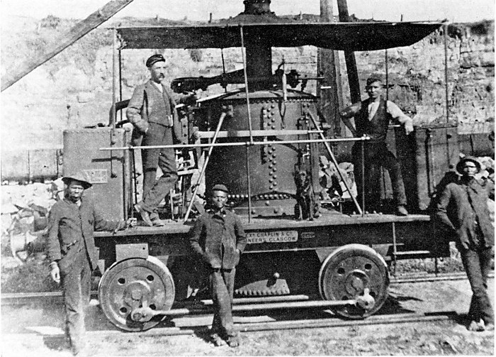 |
| Left: A Chaplin vertical-boiler locomotive in South Africa: c: 1880
This Chaplin locomotive is seen at East London harbour in South Africa. It was one of four originally obtained for breakwater construction in 1873, and then general harbour work. They worked on the 7 ft 1/4 in (2,140 mm) Brunel gauge and were rated at a nominal 15 HP. The Brunel gauge lines were finally regauged or closed between 1909 and 1912. Note the dog sitting next to the boiler.
There is more information on Wikipedia.
|
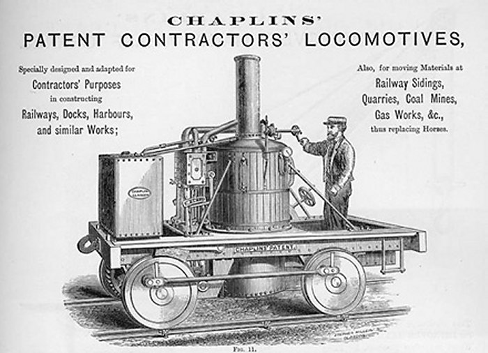 |
| Left: Advertisment for Chaplin vertical-boiler locomotives: 1881
This gives a better idea of the construction. The water tank is at the left, then comes the two-cylinder engine (two-cylinder to avoid dead-centre problems) then the rather fat boiler. The driver has his hand on the throttle-valve; normally there would be a coal-bunker behind him.
|
COCHRANE LOCOMOTIVES
 |
| Left: Cochrane vertical-horizontal-boiler locomotive: 1871
This odd locomotive was built by Cochrane & Co of Middlesborough in 1871 for their own use. It had 7in x 14in cylinders, 2ft 6.25in diameter wheels, a 5ft 6in wheelbase, and a working pressure of 100 psi. The horizontal part with the chimney presumably contained some short fire-tubes.
It seems likely that this was an experiment in combining the virtues of the vertical boiler (no chance of tubes being exposed on steep gradients, compact footprint) with the greater heating surface of a conventional horizontal boiler.
|
SENTINEL LOCOMOTIVES
One of the best-known British manufacturers of vertical-boilered locomotives was the Sentinel Waggon Works.
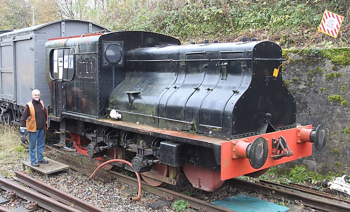 |
| Left: Sentinel vertical-boiler locomotive: 1927
This Sentinel locomotive is the former Croydon Gasworks No. 37 Joyce, built in 1927 with Works No 7109. It is under restoration at the Somerset & Dorset Railway Heritage Trust at Midsomer Norton railway station. You can read about the restoration here.
Sentinel locomotives often had this peculiar styling rather like two mobile pianos back-to-back.
Andy Chapman, the part-owner of No 7109, stands proudly by his '28-ton mistress'.
|
This example was fitted with two vertical engines, one behind each of the access doors at the front; each engine was rated at 100 HP. The middle section was taken up with a 600 gallon water tank, thus positioned so that as it emptied wheel adhesion would change in roughly the same way for each axle. The inside of the large cab was mostly taken up by the water-tube boiler, which had squat proportions like most of the other verical boilers on this page. It operated at 275 psi, quite a respectable pressure.
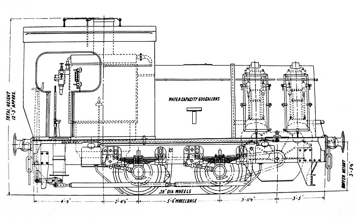 |
| Left: Sentinel vertical-boiler locomotive: 1927
This shows the two vertical engines, one behind each of the other, and the chain drive to the front axle. The two engines were spur-geared to a single shaft inside the gearbox at the front.
Each engine was a two-cylinder double-acting unit with poppet valves operated from separate inlet and exhaust camshafts. There were five settings for direction and cut-off, selected by sliding the camshafts axially.
Drawing from the book Sentinel Patent Locomotives produced by the Sentinel Waggon Works in Dec 1931.
|
There is much more on the Sentinel designs in the Sentinel gallery page here.
DE WINTON LOCOMOTIVES
Another British manufacturer of vertical-boilered locomotives was the De Winton & Co of Caernarfon, Wales, who flourished from 1854 to 1901. The partners were Owen Thomas and Jeffreys Parry de Winton.
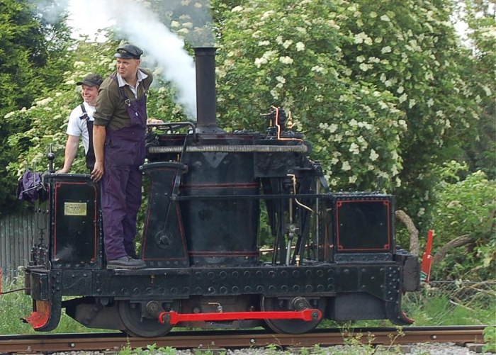 |
| Left: The de Winton locomotive Chaloner : 1877
This is the preserved vertical-boiler locomotive Chaloner The design is rather similar to the Chaplin locomotive described above. From left to right we have the coal-bunker, the driving position, the rather fat boiler, the two-cylinder engine and the water tank. It was built in 1877 and spent it s working life in slate quarries. It can usually be found at the
Leighton Buzzard Light Railway.
The engine is driving the right-hand axle directly; thanks to Ian Childs for confirming this.
2 ft gauge (610 mm)
|
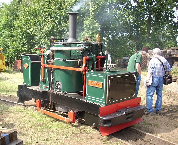 |
| Left: Modern replica of de Winton locomotive: 2008
This replica was built by Alan Keef Ltd of Herefordshire.
This picture gives a better view of the construction than the black paint of Chaloner. The red lever and its linkage control the forward/reverse and valve cutoff. The white pipe above is the steam supply to the engine.
|
HEAD WRIGHTSON LOCOMOTIVES
The firm of Head Wrightson was a Teeside manufacturer that existed from 1860 to the 1970s. They built locomotives that were very similiar to those of Chaplin and de Winton, with exactly the same layout of water tank, two-cylinder vertical engine, boiler, driving position and coal bunker.
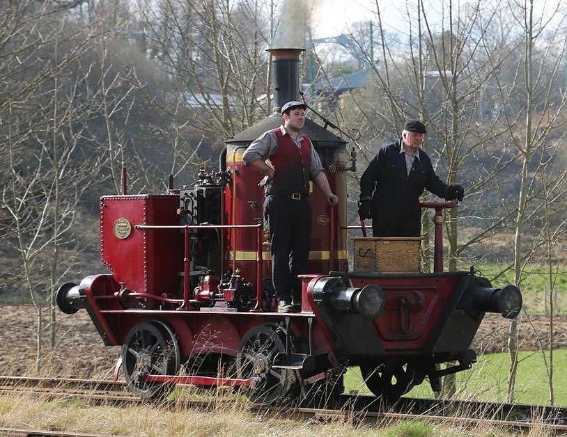 |
| Left: Restored Head Wrightson locomotive: 1871
This Head Wrightson locomotive, known as Coffeepot No 1, was restored by Beamish_Museum in County Durham. There is much info on the details of restoration at
Beamish Transport Online.
The locomotive was supplied to the Dorking Greystone Lime Company in 1871.
|
This is the only design in which it is currently known that it had a separate water pump to feed the boiler. The pump is a two-cylinder type, was made by Hickey of London to a design by Worthington Simpson, and it can be seen mounted at the foot of the boiler. The boiler feed provisions of the other locomotive designs in this gallery are unknown; no pumps are visible. The likelihood is that they had pumps worked from the engine crankshaft, in which case they would have to run up and down a bit of track to feed the boiler.
THE GREENWOOD & BATLEY LOCOMOTIVE
This thoroughly remarkable tramway locomotive was built by Greenwood & Batley in 1878 for Mr Loftus Perkins, an English engineer who was particularly involved in developing central heating and refrigeration. The high-pressure propulsion system was provided by Loftus Perkins, who developed it, and applied it also to ships. He was the youngest of three generations of remarkable engineers, starting with Jacob Perkins (1766 - ) Angier March Perkins ( - ) and Loftus Perkins (1834 - 1891).
The locomotive has so many unusual features that it is hard to know in which gallery of The Museum it should be placed. It certainly had a vertical boiler, but a boiler with a working pressure of 500 psi, which would earn it a place in the high-pressure galleries. But then it was also a condensing locomotive, was one of the very few locomotives using triple expansion, and had a geared jackshaft drive in a very unusual scotch-crank arrangement. The propulsion system was provided by Loftus Perkins, who developed it.
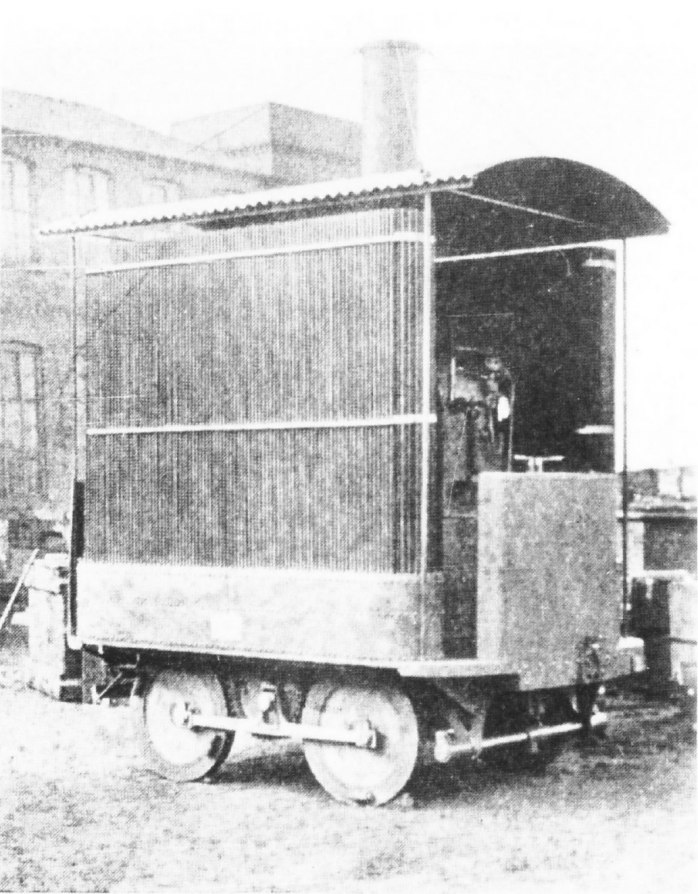 |
| Left: Greenwood & Batley vertical-boiler locomotive: 1878
The locomotive looked very much like a garden shed on wheels. The array of small vertical tubes was an air-cooled condenser.
The vertical water-tube boiler and the triple expansion engine were mounted side-by-side. The chimney can be seen to be stayed to the four corners of the corrugated-iron roof.
The vertical engine had a single-acting HP cylinder 3.125" in diameter, and a double-acting IP cylinder of 5.5" in diameter, arranged so the gland between the HP and IP cylinders was not exposed to the full temperature of the high-pressure steam, about 450 deg F. (232 degC) The two cylinders worked in tandem on the same piston rod with a common stroke of 9". The LP cylinder was 7.5" in diameter and mounted on a second piston rod, so there were only two cranks and the engine was very compact.
The engine was coupled to a jack-shaft by spur gearing, and there was a scotch-crank coupling rod on each side of the locomotive, between the axles.
Apologies for poor image quality. This seems to be the only photograph in existence.
|
 |
| Left: Greenwood & Batley vertical-boiler locomotive: 1878
This section shows the extensive banks of condenser tubes on each side. The engine is on the left and the vertical water-tube boiler on the right.
|
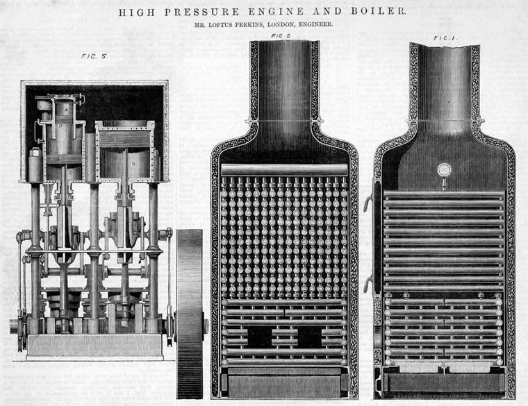 |
| Left: The Perkins high-pressure system: 1877
On the right is the water-tube boiler; it seems to have a very small steam header tank.
On the right can be seen the triple-expansion engine. A is the HP cylinder, with trunk piston D. B is the IP cylinder below it. C is the LP cylinder. The cylinders were steam-jacketed to prevent condensation; steam direct from the boiler was passed through coils of small-bore pipe that were embedded in the cylinder castings. This is represented by black dots on the cylinder walls in the drawing. Also, the whole triple-cylinder assembly appears to be enclosed in a lagged box.
Little can be deduced about the valves and valve-gear from the drawing; three eccentrics can be seen on the crankshaft, but it is not clear what they operate.
It is not certain where this image was published, but judging by the style it was probably in The Engineer.
|
The locomotive was tried on Leeds Tramways but does not appear to have been a success, and its ultimate fate is currently unknown. This all seems like remarkably advanced technology for tramway work, and it is difficult to see that triple-expansion would have given much of a cost saving.
Greenwood & Batley, were a large engineering manufacturer with a wide range of products, including tramcars, armaments, textile machinery, electrical equipment, and printing and milling machinery. They already had a track record (ha!) for unconventional power, as in 1876 they built a tram powered by compressed air.
The Perkins system was also also applied to a 79-foot steam yacht "Emily" built for Mr Perkins by Forrest and Son of Limehouse, London; Perkins married Emily Patton so not much mystery there about the name. A Perkins Watertube Boiler was fitted working at 400 psi; extremely high compared with current marine practice. A triple-expansion engine which was a larger version of the locomotive engine was fitted.
One of Mr Perkins other ideas was an early heat pipe. He used wrought-iron tubes sealed at both ends and partially filled with water, calling them "heat conductors" or "Perkins Tubes". They were re-invented at General Motors in 1942, and again at Los Alamos National Laboratory in 1963.
The Perkins company went on to become Baker-Perkins in 1923. The main factory seems to have closed in 1992; it is not clear if some of the subsiduaries are still operating.
Some of the information here was derived from 'Vertical Boiler Locomotives' by Rowland A S Abbott
THE RIGI RACK LOCOMOTIVE
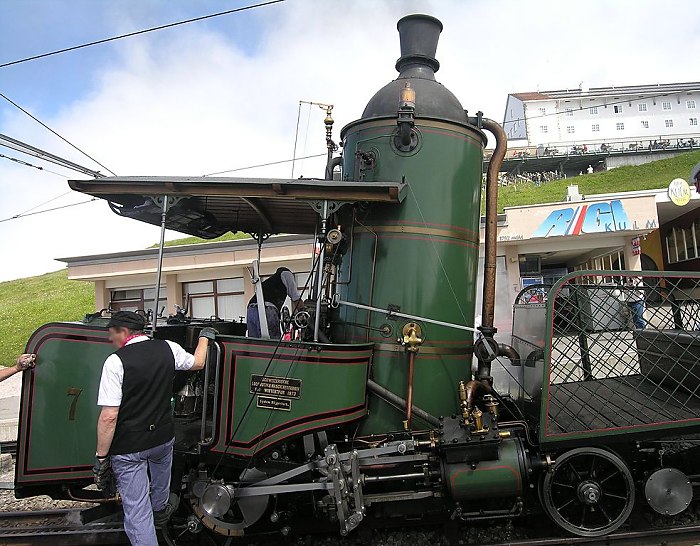 |
| Left: Rigi vertical-boiler locomotive: 1881
Built in 1873 by SLM of Winterthur for use on the Rigi Railway System in Switzerland, this is the oldest Swiss locomotive still surviving, and also the only standard-gauge vertical-boiler rack locomotive left in the world. It uses the Riggenbach rack system. The two cylinder steam engine allegedly gives 196 HP power at a speed of 7.5 km/h.
As can be seen from the photograph, on some parts of the line the boiler is far from vertical, and this is a good example of such boilers' tolerance for inclines. The locomotive was taken out of service in 1937 when the Rigi railway was electrified, but was returned to use in 2009.
|
OTHER VERTICAL-BOILER LOCOMOTIVES
There are a few other vertical-boiler locomotives already in the Museum, such as:
The grasshopper locomotives. (Jackshaft drive page)
The Boston-Ohio crab locomotives. (Jackshaft drive page)
BIBLIOGRAPHY
The definitive guide to British vertical-boiler locomotives is:
'Vertical Boiler Locomotives' by Rowland A S Abbott, published in the UK by The Oakwood Press 1989
The book lists 82 manufacturers of vertical-boiler locomotives.


