Some of the more unusual steam locomotives had 'Duplex drive' where separate cylinders drove wheels or sets of wheels that were not all coupled together. This is otherwise known as 'divided drive'. Articulated locomotives have separate driving arrangements but are not considered to use duplex drive; a rigid wheelbase is required.
Duplex locomotives have a good Wikipedia page.
The usual motivation was to halve the stresses in the connecting rods that communicated the power of the cylinders to the driving wheels. In a conventional locomotive there is on each side one connecting rod driving one crank, and the other wheels are driven from that one by coupling rods. Clearly there is something of a bottleneck as on each side all the power of the engine has to go through one connecting rod and one crank-pin, and as US locomotives grew in size and power this was becoming a problem. Another issue is that the connecting rod has to be of massive construction and so is difficult to balance.
There is however, a rather obvious snag to this concept. Wheelslip can now happen in two ways rather than one, and this was a serious problem with most if not all of the duplex designs. To see how destructive wheelslip can be, consider the Blue Peter accident in 1994.
There is a rather grim video of the accident on Youtube.

THE PETIET LOCOMOTIVES: 1863
Jules Petiet of the Nord railway in France produced two duplex-drive designs in the 1860's.
The first was a tank engine in 1862 with independent driving axles at each end but three supporting axles in the middle; I suppose it would be called a 0-2-6-2-0 configuration.
A later design of 1863 had two sets of independently driven axles making it an 0-6-6-0.
These locomotives are fully described on the page of Petiet's French experiments.
THE LNWR TEUTONIC LOCOMOTIVES: 1882
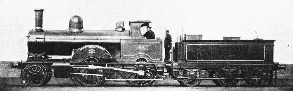 |
| Left: The Webb Teutonic class: 1882
The Teutonic 2-2-2-0 class were the largest of several compound engine types built by Francis Webb, the Chief Mechanical Engineer of the LNWR from 1871 to 1903. Two 14" diameter outside high pressure cylinders drove the rear driving wheels, and their exhaust was delivered to a huge 30" diameter low-pressure cylinder mounted under the smokebox which powered the front driving wheels. The driving wheels were not coupled together and the class, like all of Webb's compounds, became notorious for wheelslip and jerky starting, and it was not uncommon for the two driving axles to start rotating in opposite directions; this did nothing to enhance the reputation of Mr Webb. Despite this the Teutonics could perform well when carefully handled. The single low-pressure cylinder exhausting to the chimney gave a very distinctive exhaust beat.
The Webb duplex locomotives were rapidly scrapped by Webb's successor
The Webb Teutonics have a Wikipedia page.
|
THE JAMES TOLEMAN LOCOMOTIVE: 1892
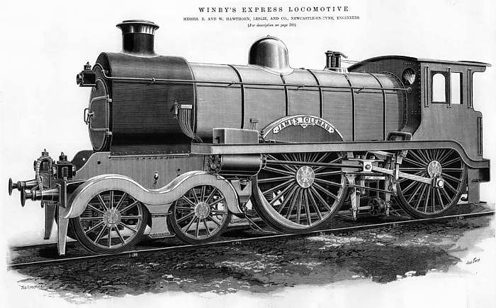 |
| Left: The James Toleman locomotive: 1892
The James Toleman was a simple (non-compound) locomotive with four cylinders. The two cylinders outside the frames drove the rear driving wheels while the two cylinders under the smoke-box and inside the frames drove the front driving wheels. There was no mechanical connection between the two.
It had an unusual boiler composed of two joined near-circular sections, very much like the Thuile locomotive. The locomotive was designed and financed by a Mr Winby of London, and built by Hawthorn, Leslie & Co of Newcastle, England. Who James Toleman was and why the locomotive was named after him remains mysterious.
The James Toleman proved unsatisfactory in tests due to a lack of steaming power and unreliablity. It also had trouble with wheelslip. Mr Winsby retained ownership throughout; he became disenchanted with the project and abandoned it.
|
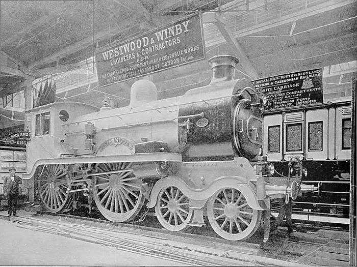 |
| Left: The James Toleman locomotive: 1893
The James Toleman is seen here exhibited at the 1893 Chicago Worlds Fair in 1893. The sign above the locomotive reveals that the elusive Mr Winby was in partnership with a Mr Westwood, and that they were based in London.
|
THE NORD RAILWAY 701 LOCOMOTIVE: 1895
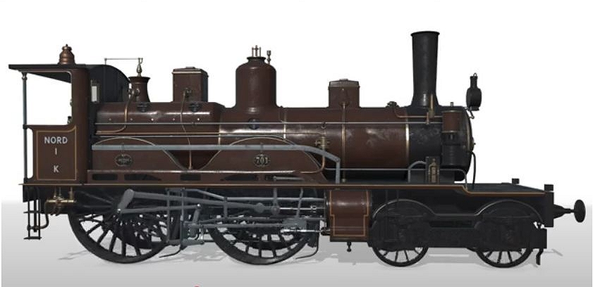 |
| Left: The Nord 701 Duplex locomotive: 1885
In 1884, the Chemin de Fer Nord's chief engineer Gaston Du Bousquet contacted Alfred de Glehn, then the director of the Soci�t� alsacienne de constructions M�chaniques, and asked if he could design a successor to the 4-4-0 Outrance type of locomotive. These were a simple-expansion two-inside-cylinder design, and express trains of increasing weight were becoming too much for them.
(Du Bousquet also introduced some unique articulated locomotives, described in this gallery of the Museum)
The prototype was finished in 1885 and designated 120 Nord 701. It was a 2-2-2-0 compound design with two inside HP cylinders powering the first driving axle, while two outside LP cylinders powered the second driving axle. There was no coupling between the driving axles, so it was a duplex design. There was a Belpaire firebox and a large steam dome. It was rebuilt in 1892, being given a four-wheel bogie at the front.
De Glehn was apparently inspired by Sir Francis Webb's compound locomotives on the LNWR. The LNWR locomotives had two high pressure (HP) cylinders powering the rear driving axle, and a single central inside low pressure (LP) cyinder to power the front driving axle. What is strange is that Webb's duplex locomotives were widely known to be unsatisfactory, with horrible wheelslip and starting problems. Did de Glehn not know this?
There is a very nice animation of Nord 701 in motion on YouTube. The illustration at left comes from the animation.
|
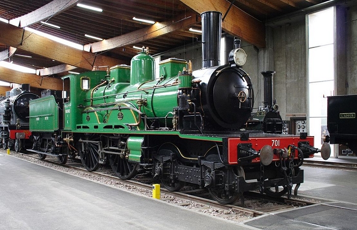 |
| Left: The Nord 701 Duplex locomotive at Mulhouse: 1885
The Nord 701 Duplex locomotive is preserved at the Cit� du Train museum in Mulhouse, Alsace, France.
Note that the connecting rod to the rear driving axle is missing, for reasons unknown.
The Nord 701 has a french Wikipedia page.
Many thanks to Andrew Chern for drawing this locomotive to my attention and providing much information.
|
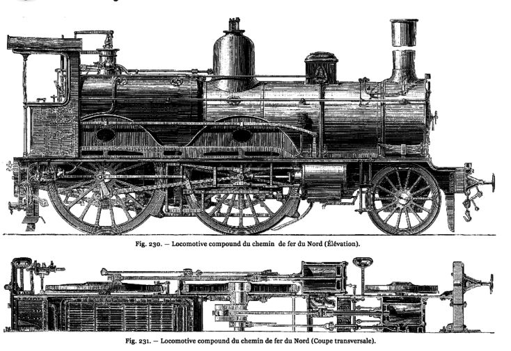 |
| Left: The Nord 701 Duplex locomotive: 1885
These drawings show the duplex Nord 701 before being given a four-wheel bogie at the front. Note the inside cylinders in the bottom drawing.
Many thanks to Andrew Chern for drawing this locomotive to my attention and providing much information.
|
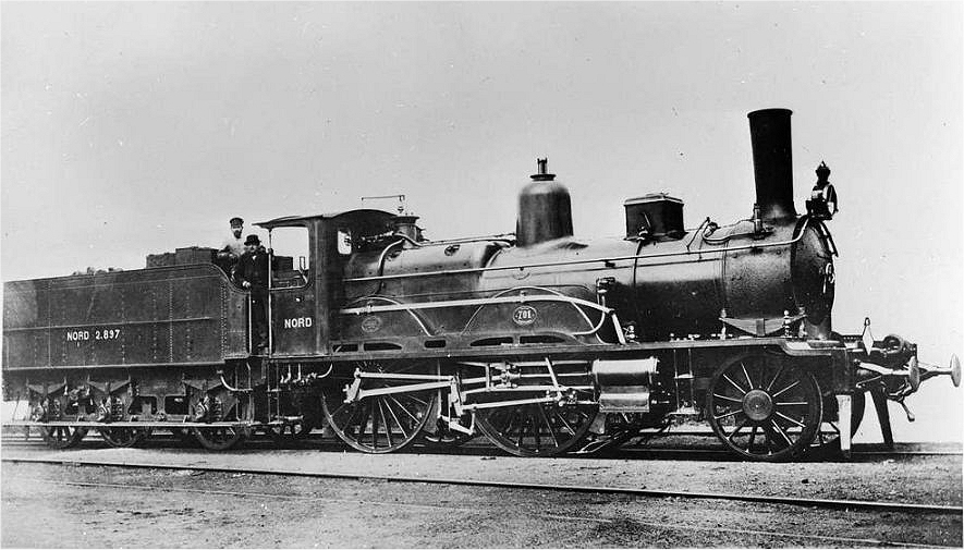 |
| Left: The Nord 701 Duplex locomotive: 1885
The Nord 701 with the original 2-wheel bogie at the front.
At first I thought this and the image below were the same photograph, with the background retouched out, (as was common practice at the time) but not, because the return crank on the rear driving wheel is at different angles. The retouching seems to have been a bit over-enthusiastic here as the rod running to the square sandbox is missing compared with the lower image.
Many thanks to Andrew Chern for drawing this locomotive to my attention and providing much information.
|
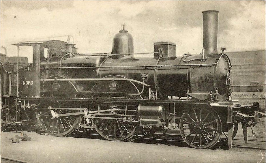 |
| Left: The Nord 701 Duplex locomotive: 1885
Many thanks to Andrew Chern for drawing this locomotive to my attention and providing much information.
|
THE SAXON RAILWAY XV HTV DUPLEX LOCOMOTIVES: 1916
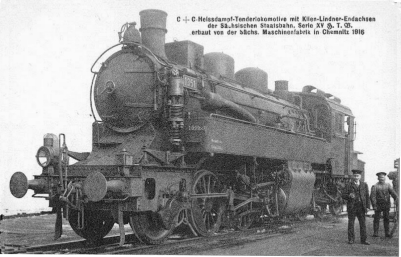 |
| Left: The Saxon Series XV HTV locomotive: 1916
The Series XV HTV compound, of which two were built in 1916 for banking duties on the Saxon State Railway, was unusual in more than one way. It used Klien-Lindner axles so it get round curves without the complexity of articulation. The two sets of driving wheels were not coupled in any way, so this was a duplex drive locomotive. Note that there are outside frames at each end of the locomotive, to accomodate the Klien-Lindner axles.
The locomotives proved expensive to maintain, and no more were built.
This axle system are described in detail on the Klien-Lindner gallery of the Museum.
The design has a Wikipedia page, which gives full technical specs.
|
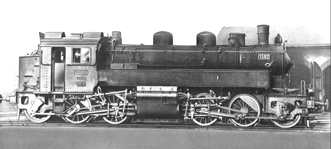 |
| Left: The Saxon Series XV HTV locomotive: 1916
This gives an excellent view of the double-cylinder arrangement.
|
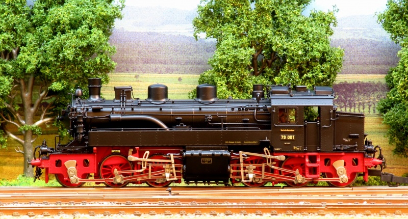 |
| Left: Model of the Saxon Series XV HTV locomotive: 1916
The picture here is of a model, builder unknown, because no photograph has yet been found which clearly shows the most unusual double-cylinder arrangement.
Note the twin steam domes, which were linked by a pipe inside the boiler.
|
THE PLM RAILWAY 151A LOCOMOTIVE: 1932

|
Above: The PLM 151A locomotive: 1932
|
The most famous and most successful duplex locomotives In France were the ten 2-4-6-2 (151A) compound locomotives built in 1932 for the Paris-Lyons-Marseilles company (PLM) to haul heavy goods trains on the 0.8% grade between Les Laumes and Dijon.
The low-pressure cylinders drove the first set of coupled axles, and the high pressure cylinders the second set of coupled axles. The front and back crankpins were set at 180 degrees so the back and forth forces from the movement of the pistons was balanced out. The 151A was therefore a balanced locomotive.
Most importantly, the two sets of drivers were linked with inside connecting rods and inside cranks on the 2nd and 3rd driving axles, so despite having separate groups of cylinders these locomotives were not true duplex, but actually 2-10-2, which probably explains their success. This arrangement is apparently sometimes called 'conjugated duplex'. Certainly the great Andre Chapelon considered them to be of the 2-10-2 configuration, and I don't plan to argue with him. The driving wheels had a diameter of 1.50 m (4' 11"). The rear cylinders were angled upward to reduce the distance required between the second and third driving axles. The cutoffs for the LP and HP cylinders were linked so the work done was in the ratio 2:3, since the LP cylinders drove two axles directly but the HP cylinders three. This minimised the stresses on the internal connecting rods.
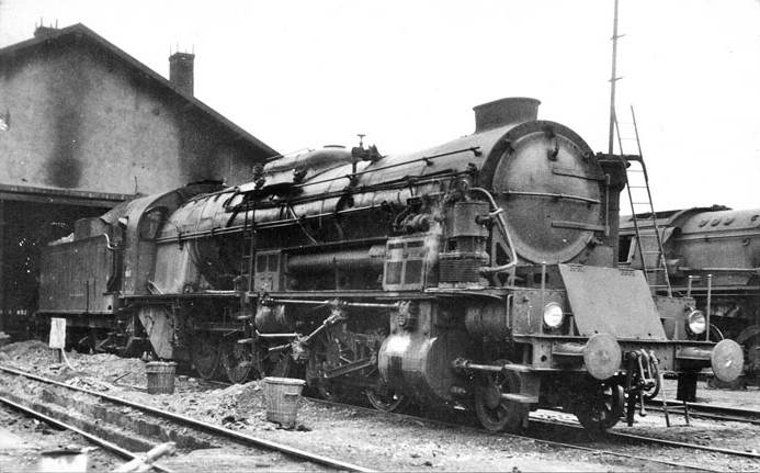 |
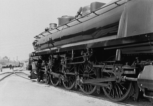
| Above: A PLM 151A locomotive: 1932
An ex-PLM 151A looking a little battered at Audun-le-Roman after its transfer to the Est region in July 1953.
The large pipe running between the two valvegear boxes above the cylinders presumably conducted the HP cylinder exhaust steam to the LP cylinders at the front.
|
|
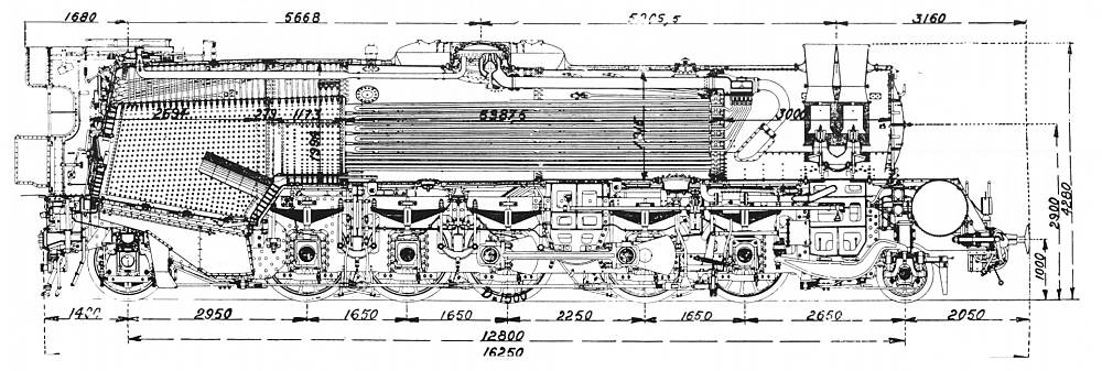
Above: Section of the PLM 151A locomotive: 1932. Dimensions are in millimetres
One of the connecting rods between the 2nd and 3rd driving axles can be seen; the wedge-shaped thing to its immediate right is its balance weight. Note the double blastpipe with intermediate petticoats, which replaced the original Tr�fle exhaust.Andre Chapelon and Ky�sti Kyl�l� were the inventors of the Kylchap exhaust.
|
The locomotive can be found on the Wikipedia page for Duplex drive.
The 151A has its own Wikipedia page
but it is in French.
THE BALTIMORE & OHIO Class-N1 4-4-4-4 LOCOMOTIVE: 1937
 |
| Left: The George H Emerson locomotive No 5600: 1937
The great flowering of the duplex drive concept occurred in the USA toward the end of the steam era. It was begun by the
Baltimore and Ohio Railroad (B&O), who produced a 4-4-4-4 design called "George Emerson" (the name of the Chief Engineer) and numbered 5600, in 1937. It was built in their own workshops with out help from Baldwin, their usual locomotive supplier. It had a water-tube boiler. The locomotive is shown here on display at New York on 5th August 1939.
Boiler pressure: 350 psi
Power output: 3936 hp
Weight of loco: 175 tonnes
|
 |
| Left: The George H Emerson locomotive No 5600: 1937
Showing the rear motion work and the rear cylinders snuggled up to the firebox.
|
 |
| Left: The George H Emerson locomotive No 5600: 1937
This demonstrates another snag with putting the second pair of cylinders at the rear. Steam leakages could obscure the driver's vision.
|
The design was not very successful. Putting the rear pair of pistons beside the firebox meant the locomotive was kept to the same coupled wheelbase as the B&O's current 4-8-2 engines, but space there was very limited so there were compromises in firebox and cylinder size. The piston and valve rods also suffered from grit from the firebox. It was tested until 1943 and then withdrawn. It was not repeated.
The PRR N1 locomotive has a short Wikipedia page that gives the full specs. The locomotive can also be found on the Wikipedia page for Duplex drive.
THE PENNSYLVANIA RAILROAD Class S1 6-4-4-6 LOCOMOTIVE: 1940
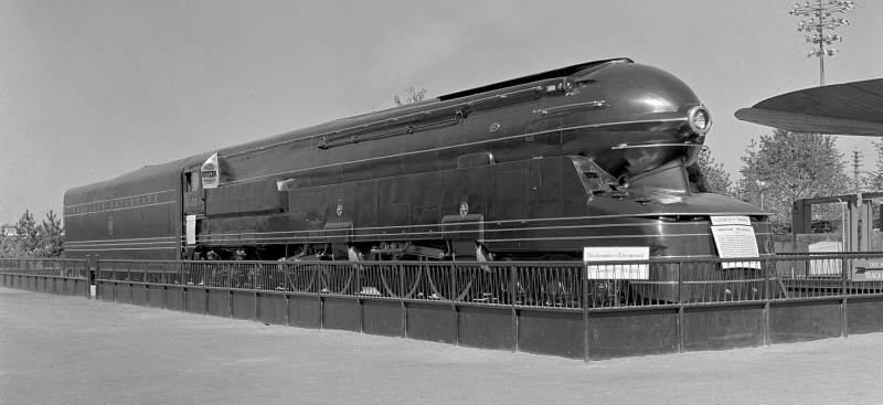 |
| Left: The Pennsylvania Railroad S1 locomotive: 1940
The Pennsylvania Railroad started their affair with duplexes by building what has been described as the largest steam locomotive. The S1 No 6100 was a one-of-a-kind 1939 6-4-4-6 streamlined design with enormous 84-inch driving wheels. It was at the time the longest and heaviest rigid frame reciprocating steam locomotive ever built. (but see the PRR Q2 of 1944) Not surprisingly it was known as the "Big Engine", It was demonstrated running on rollers (under its own steam power) at the 1939-40 World's Fair in New York.
|
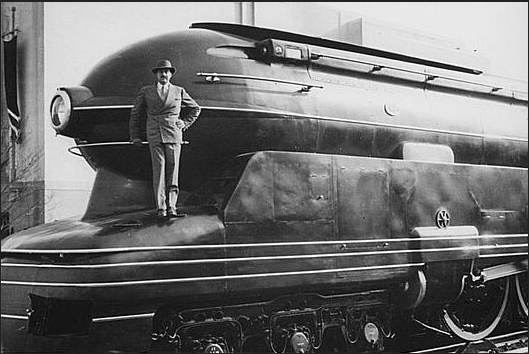 |
| Left: The Pennsylvania Railroad S1 locomotive: 1940
The streamlined casing was designed by Raymond Loewy seen here standing on the casing. "Hey, mister, that's me up on the smokebox..."
|
Boiler pressure: 300 psi
Power output: not available
Weight of loco: 276 tonnes
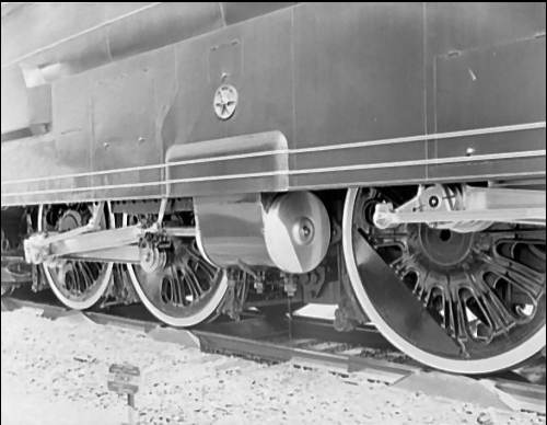 |
| Left: The Pennsylvania Railroad S1 locomotive: 1940
Here is close-up of the rearward cylinder. Note the relatively lightly proportioned connecting rods, compared with the massive girders used on non-Duplex locomotives.
|
The S1 was taken out of use in 1945 and scrapped in 1949.
The PRR S1 locomotive has its own Wikipedia page.
THE PENNSYLVANIA RAILROAD Class T1 4-4-4-4 LOCOMOTIVE: 1942
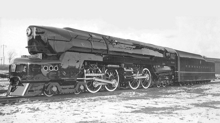 |
| Left: The Pennsylvania Railroad T1 locomotive: 1942
Two T1's, Nos 6110 and 6111, were delivered by Baldwin to the PRR in April and May 1942, intended for high-speed passenger service. These were of advanced design, with poppet valves. These valves were only rated to operate at up to 100mph, and were prone to fail if the locomotive exceeded this speed, which it could easily do.
Following good reports of the two prototypes, a production series of 50 locomotives was built, again with streamlining by Raymond Loewy, though in my view the result is pretty ugly compared with the S1 above. Fifty locomotives, Nos 5500 to 5549, with 80" drivers, were built in 1944-46, with construction split between the PRR's own Altoona Works and Baldwin. By this time the use of steam on US railroads was declining.
|
Boiler pressure: 300 psi
Power output: 6550 hp (Test of No 6110 in 1944)
Weight of loco: 224 tonnes
All T1's were out of use by 1952, and were scrapped between 1951 and 1956, but the T1 Locomotive Trust is planning to build a new one, with the goals of running a mainline steam excursion service, and- wait for it- to set a new World Speed Record for a steam locomotive.
 |
| Left: The Pennsylvania Railroad T1 locomotive: 1942
No 5544 is shown, apparently not in steam.
|
The T1 has a Wikipedia page, which gives full specs.
In this Youtube video there is a frightening example of T1 wheelslip at 1min 22 seconds.
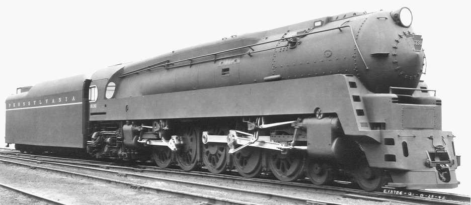
THE PENNSYLVANIA RAILROAD Class Q1 4-6-4-4 LOCOMOTIVE: 1942
|
Above: The Pennsylvania Railroad Q1 locomotive: 1942
|
The Q1 was an attempt to apply the duplex configuration to a fast goods engine; it was delivered in May 1942. No. 6130 had the same cylinder layout as the B&O George H Emerson, with the second set of cylinders at the rear. The cylinder sizes and strokes were different, which is highly unusual. (except for compound designs, of course) This duplex attempted to equalise the work done by the leading 6-wheel set and the rearward 4-wheel set by having a larger front pair of cylinders with 23" diam pistons and a stroke of 28", and smaller rear cylinders with 19.5" diam pistons and a shorter 26" stroke.
Also unusual for a goods locomotive was the partial streamlining, and the bullet nose rather than a conventional smokebox door.
The Q1 was a one-off experiment and It was described as "having all the drawbacks of the B&O loco". These included the location of the rear cylinders; they compromised firebox size and were subjected to grit and dust. Furthermore the long pipework caused thermal losses. It remained in intermittent service (it required a good deal of maintenance) until late 1946, when it was withdrawn and put into storage, and dismantled around 1949. It was the basis of the PRR Q2 series.
Boiler pressure: 300 psi
Power output: not available
Weight of loco:
The Q1 has a Wikipedia page, which gives full specs. (except the power output)
There appear to be no Youtube videos of the real Q1 in action, though there are a few of model Q1's.
Here is a fine example.
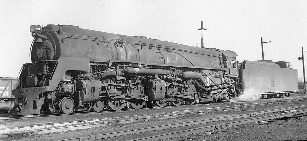
THE PENNSYLVANIA RAILROAD Class Q2 4-4-6-4 LOCOMOTIVE: 1944
|
Above: The Pennsylvania Railroad Q2 locomotive: 1944
The Pennsylvania Railroad's class Q2 began with a single prototype built in 1944. (No 6131) Twenty-five production models (Nos 6175-99) were built in 1944-45. Unlike most of the duplexes (the PLM 151A being a notable exception, but arguably not a real duplex) they were very successful. The reason was that at last someone had got around to fitting an anti-slip system that automatically reduced the power to the wheel set that was rotating too fast.
Boiler pressure: 300 psi
Power output: 7987 hp
Weight of loco: 276.4 tonnes
The Q2's were the biggest non-articulated locomotives ever built, though as far as I can see they wre only half a ton heavier than the S1. They were the most powerful locomotives ever static tested, producing 7,987 cylinder horsepower on the PRR's static test rig.
|
The Q2's were considered a successful design, but did not last long in service. They were not much more capable than the conventional 2-10-4 PRR J1's, but had much higher operating costs and greater maintenance requirements. As a result they had all been withdrawn by 1951, though the J1's carried on until 1958-59.
The Q2 has a Wikipedia page, which gives full specs.


