Trials were undertaken on the Chemin de Fer de l'Etat line between Chartres and Thouars, and a speed of 117 km/hr (73 mph) was reached pulling a load of 186 tonnes. (183 long tons)
The trials were ended when Thuile was killed in an accident in June 1900, and the prototype was returned to the manufacturer. The locomotive was scrapped in 1904, but the tender survived until at least 1946, when it was noted at Saint Pierre-des-Corps.
THE TECHNICAL DATA
BuilderSchneider et Cie of Creusot
Driver diameter2.50 meters (98.43 in)
Boiler cross-sectnMost peculiar (see below)
Boiler upper diam54 in
Boiler lower diam48.5 in
Boiler tubes183 of them. Ribbed, 2.25 in diam
Heating surface2941 ft2
Working pressure15 kg/cm2 (213 psi)
Firebox typeBelpaire
Grate area4.68 m2 (50.38 ft2)
Valve gearWalschaerts
TenderOne 2-axle, one 3-axle bogie
Water27.5 m3 (7300 gallons)
Coal7 metric tons
Power800 to 900 DBHP
| | | | | | | | | | | | | | | | | | | | | | | | | | | | | |
| Some of the technical data here was kindly provided by Claude Bersano, to whom I am most grateful.
All irresponsible speculation is mine.
One of the problems with this kind of design must have been communication between driver and fireman. Possibly there was a cord-operated bell, or even a voicepipe, (Why not? They were used in British railmotors in the early 20th century- these had to travel in either direction- and even in early two-man aircraft) but helping with spotting signals and so on would have required some pretty good co-ordination. The same problem appears to apply to camelback locomotives.
|
The least explicable feature of this design was the weight distribution. The total engine weight in working order was 165,000 lb approx.
The driving wheels carried only 65,000 lb, (16,000 lb per wheel)
The six-wheel rear bogie carried 59,000 lb, less than 10,000 lb per wheel. Sinclair pointed out that this would give 15,000 lb per wheel with a four-wheel bogie, which would seem preferable to the extra pair of wheels.
The four-wheel bogie at the front therefore carried 41,000 lb.
It is clear that only 39% of the total weight was available for adhesion. Wheelslip must surely have been one of the problems.
 |
| Left: The Thuile locomotive.
Looking at this picture, I am brought to wonder about access to the smokebox for tube-cleaning. Was the cab removable?
From "Glaser's Annalen"
|
I am indebted to Mr Robin Barnes for the following additional information:
Thuile, who was Engineer to the Port of Alexandria
Authority in Egypt, set up a company titled La Societe Des Trains Internationaux, in which unlike the Orient Express, the same locomotive would haul his luxury train the breadth of Europe. He did indeed die during the trials but sad to relate it was his brainchild that killed him. In June l900, running between Chartres and Orleans his locomotive, 'Trains Internationaux No.1' derailed and, according to the French National Railway Museum at Mulhouse, in English translation, "hurled its unfortunate designer fatally against a lineside pole".
It is now seems all too clear why enthusiasm for this design was limited; however, according to another account, Thuile simply leaned too far out from the locomotive and was brained by a lineside pole.
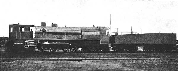
Above: Side view of the Thuile cabforward locomotive.
Above: Side view of the Thuile tender.

Above: Side sectional view of the Thuile.
The three layers of lateral boiler stays are seen end-on.
The function of the small exhaust pipe exiting through the roof of the cab is obscure. Is it from the brake air compressor?
 |
| Left: Cross-section of the Thuile, showing the unusual boiler design.
The basic idea was to go faster by having bigger driving wheels. This meant the boiler had to fit between them, ruling out the usual cylindrical shape. Any departure from a circular cross-section raises engineering eyebrows because it is the most efficient configuration to resist pressure.
The Thuile boiler is a long way from circular. Lateral stays were fitted to hold the two sides together, and each side also appears to have been reinforced with some sort of girder. It all looks very awkward and must have been unnecessarily heavy.
Having said this, the Thuile never exploded; the boiler design might not have been efficient but it was competent. Several other designs used unusual boilers to fit them between the wheels;
see the Flaman boiler of 1894. (French Est railway)
|
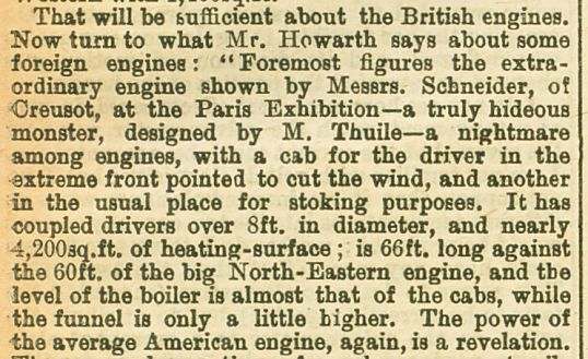 |
| Left: A less than rave review from The English Mechanic for Jan 25 1901.
Mr Howarth (whoever he was) seems more concerned about the aesthetics than the performance. Note that the heating surface given here does not agree with the table at the top of the page.
|
Biliography:
- "The Development of The Locomotive Engine" by Angus Sinclair.
- "Unusual Locomotives" Ernest Carter


