Gallery opened July 2004
Updated: 1 Nov 2025
Ritchie's balanced Locomotive updated again here.


Gallery opened July 2004 |
This problem can be minimised by adding weights to the driving wheels. These already have balancing weights which nullify the effect of purely rotating masses such as the crank pins and coupling rods. Adding more mass to these weights can balance the back-and-forth forces, at the expense of upsetting the rotational balance; the latter has bad consequences, generating an up-and-down force on the rail. When acting downwards this is known as "hammer-blow" and puts serious extra stresses on the track and its foundations, the forces increasing with the square of the speed. 180 degrees later in the rotation of the wheel it acts upwards, and in severe cases can almost lift the wheel off the rail, with dire consequences for stability. As a result, it was conventional practice to balance only a third to a half of the reciprocating mass. (The Austerity locomotives designed for military use in WW2 had no reciprocating balance at all, so they could work on hastily-laid track. Comfortable riding was not a priority; however in these conditions speeds were low and it was a perfectly sound design choice)
At least two designers appreciated that a good way to obtain good balance for both the rotating and reciprocating masses was to fit two pistons on each side, driving crank-pins set at 180 degrees so that one piston would move forward as the other moved back.
The only real difficulty was fitting two cylinders where one had grown before. Burch solved the problem by having two pistons in one cylinder, driving two different wheels. John Haswell solved it by fitting one cylinder above the other, set at a slight angle. Shaw had enough room to put two cylinders side-by-side. Strong used two inside cylinders and two outside cylinders, four in all.
![]()
THE BURCH BALANCED LOCOMOTIVE: 1837
 | Left: The Burch Oscillating Cylinder Locomotive: 1837
|
I have so far found no indication that this design was actually built. Burch was described as 'a machinist' which does not sound like he was a professional railway engineer. Full details were published in the London Journal of Arts & Sciences, Volume XI, 1838.
![]()
GEORGE STEPHENSON'S BALANCED LOCOMOTIVE: 1846
 | Left: The Stephenson & Howe balanced 4-2-0 locomotive: 1846
|
![]()
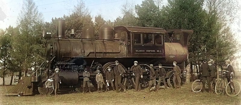
RITCHIE'S BALANCED LOCOMOTIVE: 1856
 | Left: Ritchie's balanced Locomotive: 1861
|
![]()
THE HASWELL BALANCED LOCOMOTIVE: 1861
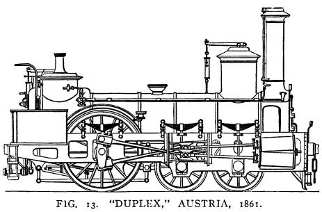 | Left: The Haswell Duplex Locomotive: 1861
|
 | Left: The Haswell Duplex Locomotive: 1861
|
![]()
THE H F SHAW BALANCED LOCOMOTIVE
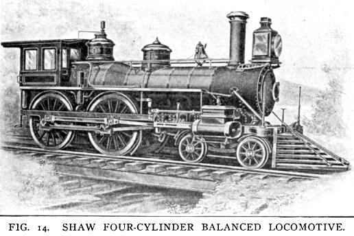 | Left: The H F Shaw Locomotive: 1881
|
One of the crank pins connected outside the driving wheel at the same position an ordinary crank pin would be located, and carried a double crank, the middle of which was supported in a bearing held in an outside frame. The connecting rods worked either side of this bearing.
The engine was equivalent to one with two cylinders 16" by 24", and driving wheels 63" in diameter. The weight in working order was given as 74,000 pounds, of which 25,600 pounds was on the front bogie. The engine was said to have been well-designed and well-built, and it saw considerable trial use in revenue-earning service, where it was said to have worked "quite satisfactorily", but no more of the type were built.
![]()
THE WOOLWICH ARSENAL BALANCED LOCOMOTIVE
The history of this 2+2+2+2 locomotive is rather obscure. It derives from the last patent taken out by Thomas Crampton, though it has little in common with what is normally though to be a Crampton design- ie all the drive coming from a single pair of wheels at the rear of the locomotive.
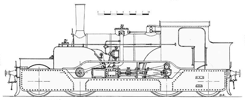 | Left: Side view of Crampton Locomotive for Woolwich Arsenal: 1880's?
|
Crampton took out a patent for a balanced duplex-drive locomotive in 1885. It is claimed that a locomotive built to this design, or very similar, was in use at the Royal Arsenal at Woolwich in the late 1880's. However there is no reference to a locomotive with a 2+2+2+2 wheel arrangement on the Wikipedia page for the Royal Arsenal Railway. It is known that Crampton did experiments with the 18in-gauge locomotives Vulcan (No 939) and Mercury (No 1075) but both these engines were of 0-4-2 wheel arrangement.
 | Left: Front view of Crampton Locomotive: 18
|
![]()
THE STRONG BALANCED LOCOMOTIVE
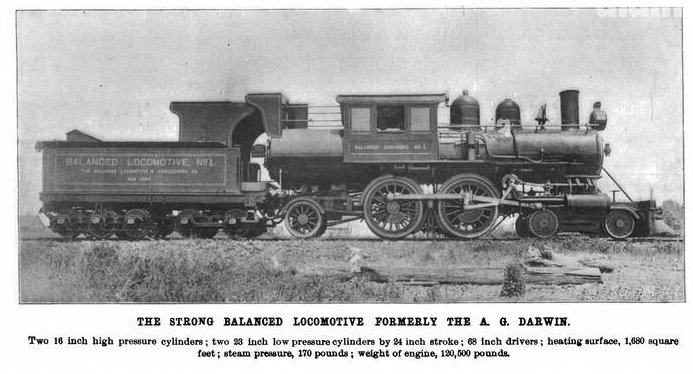 | Left: The Balanced Locomotive of Mr George Strong: 1896
|
 | Left: The four cylinders of the Balanced Locomotive: 1896
|
So how well did it work? An article called "Tests of the Strong Balanced Locomotive at Purdue University" was published in Scientific American for 21 August 1897. (Purdue University was unusual in having a locomotive test facility, run by a Professor Goss) A version not paywalled has yet to be found. You can read a letter from George Strong to the editor of the Railway Gazette here, in which Strong disagrees with Prof Goss. The Prof says that the disagreements between them "are rather fundamental" which suggest that the test were not conducted with perfect harmony between inventor and tester.
In 1897 the Balanced Locomotive & Engineering Co of New York tested the Strong balanced locomotive for hammer-blow on the Purdue static test plant, using the same procedure as Prof Goss in 1893. (the crushing of wire) "The test wwas a great success, with no hammer-blow, pitching, or yawing of the engine." Nonetheless the engine was not repeated although "During the early part of the 2oth century counterbalancing was a serious and limiting factor in American locomotive development." (Tom Morrison, The American Steam Locomotive in the Twentieth Century)
The failure to put more effort into balanced locomotives is mysterious.
 | Left: The rods and cranks of the Balanced Locomotive: 1896
|
 | Left: The Balanced Locomotive: 1905?
|
![]()
THE PLM BALANCED LOCOMOTIVES
Ten 2-4-6-2 (151A) compound locomotives were built in 1932 for the Paris-Lyons-Marseilles company (PLM) to haul heavy goods trains on the 0.8% grade between Les Laumes and Dijon. The low-pressure cylinders drove the first set of coupled axles, and the high pressure cylinders the second set of axles. The two sets of drivers were linked with inside connecting rods and inside cranks on the 2nd and 3rd driving axles, so despite having separate groups of cylinders these locomotives were not true duplex, but actually 2-10-2.
The front and back crankpins were set at 180 degrees so the back and forth forces from the movement of the pistons was balanced out. The 151A was therefore a balanced locomotive.
The 151A is described on the duplex drive page.
These are the only balanced locomotives I have found so far. If there are more they are well-hidden.
The only conclusion seems to be that the added complexity outweighed the smoother riding and reduced track impact. Since the words "hammer-blow" recur like a dismal refrain in the history of locomotive design, this is rather hard to understand.
![]()
