Wood-Gas Vehicles

Gallery opened 30 Apr 2020

Updated 15 Dec 2020

Straw-gas car added

Index improved

Links added (bottom of page)
Back to Home PageBack to The Loco Index

WOOD-GAS TECHNOLOGY

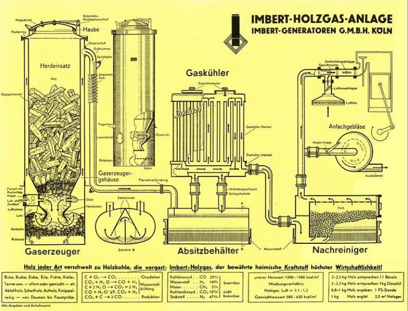
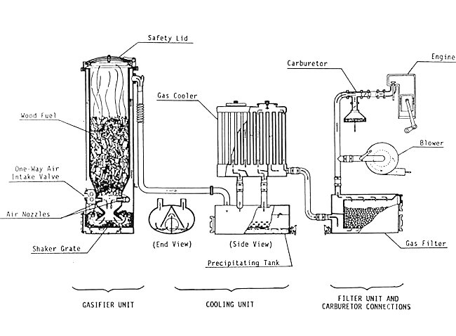
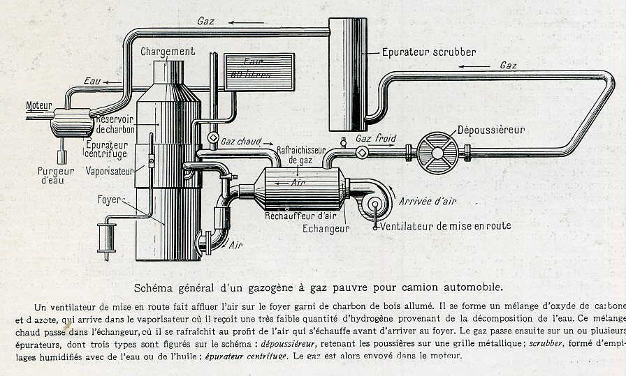
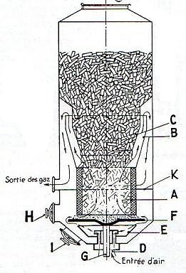
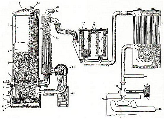
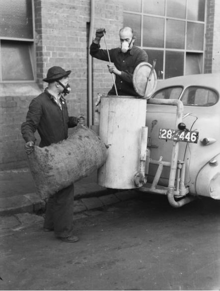
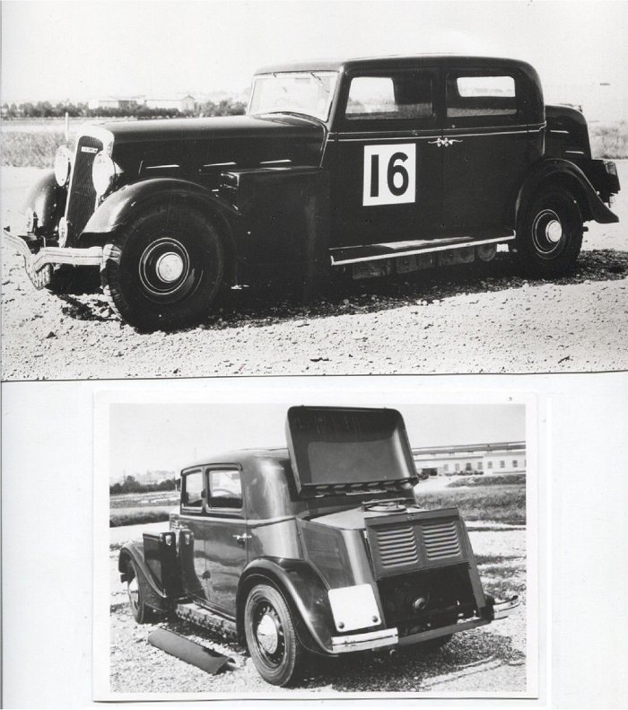
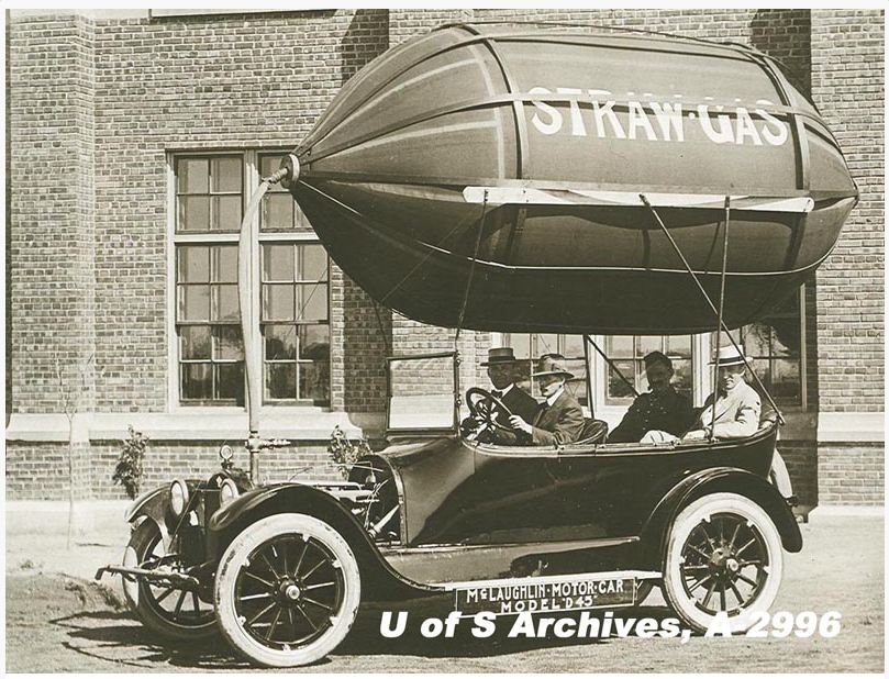
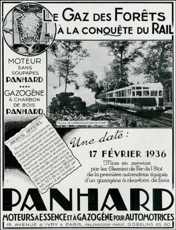
In the absence of oil, people turn to desperate measures to move themselves and their stuff around. Vehicles running on wood-gas carry around a plant for the gasification of wood, which is done by heating wood pellets, or similiar organic materials, to high temperatures in a closed vessel with a limited amount of oxygen. The heating, which can reach a temperature of 1400 °C, is done by partial combustion of the wood pellets. The wood-gas given off contains hydrogen and carbon monoxide, which can be used in an IC engine with only minor modifications. The history of wood gasification goes right back to the 1870s, when it was used instead of coal-gas for street lighting and cooking.

Wood-gas consists very roughly of 50% nitrogen, 8% carbon dioxide, 20% carbon monoxide, 18% hydrogen, and 4% methane. The nitrogen and carbon dioxide that make up 58% are of course inert as far as the engine is concerned; it is a low energy-density fuel. It however must be mixed with air to make it combustible, and this adds even more inert nitrogen. Thus the power output from an engine is much reduced when it runs on wood-gas rather than petrol.

Be aware that producer gas can also refer to gas produced by the gasification of coal or anthracite. It may also refer to water-gas, which is produced by a modified process by which adds the injection of water or steam to obtain a higher heat content gas with a higher hydrogen content; it is a particularly dangerous variant as it contains large amounts of hydrogen and carbon monoxide, making it both explosive and very poisonous. Some wood-gas systems used water injection to get better gas, but this also takes heat out of the process, and in most cases seems to have been regarded as an undesirable complication to an already awkward system.

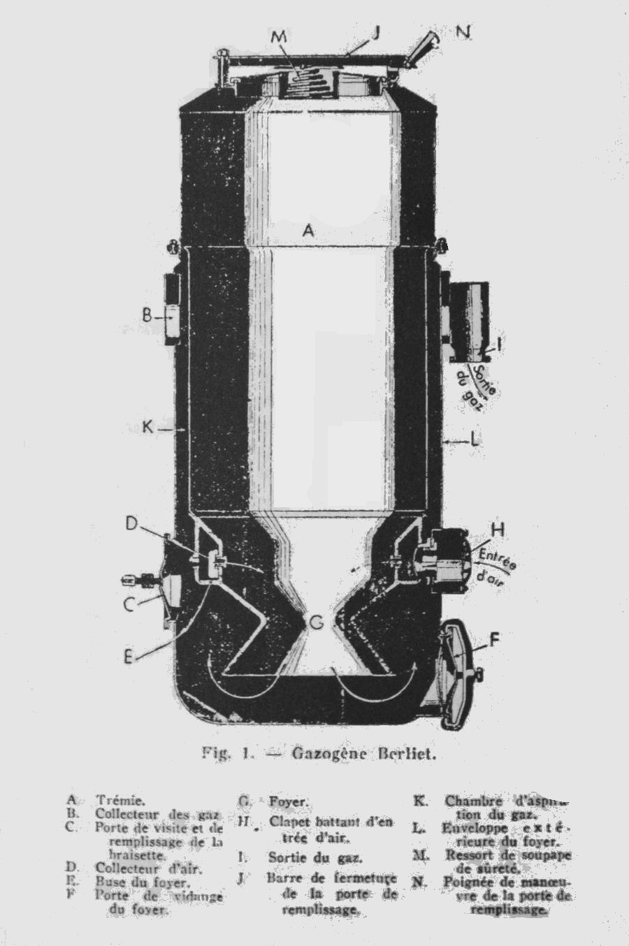
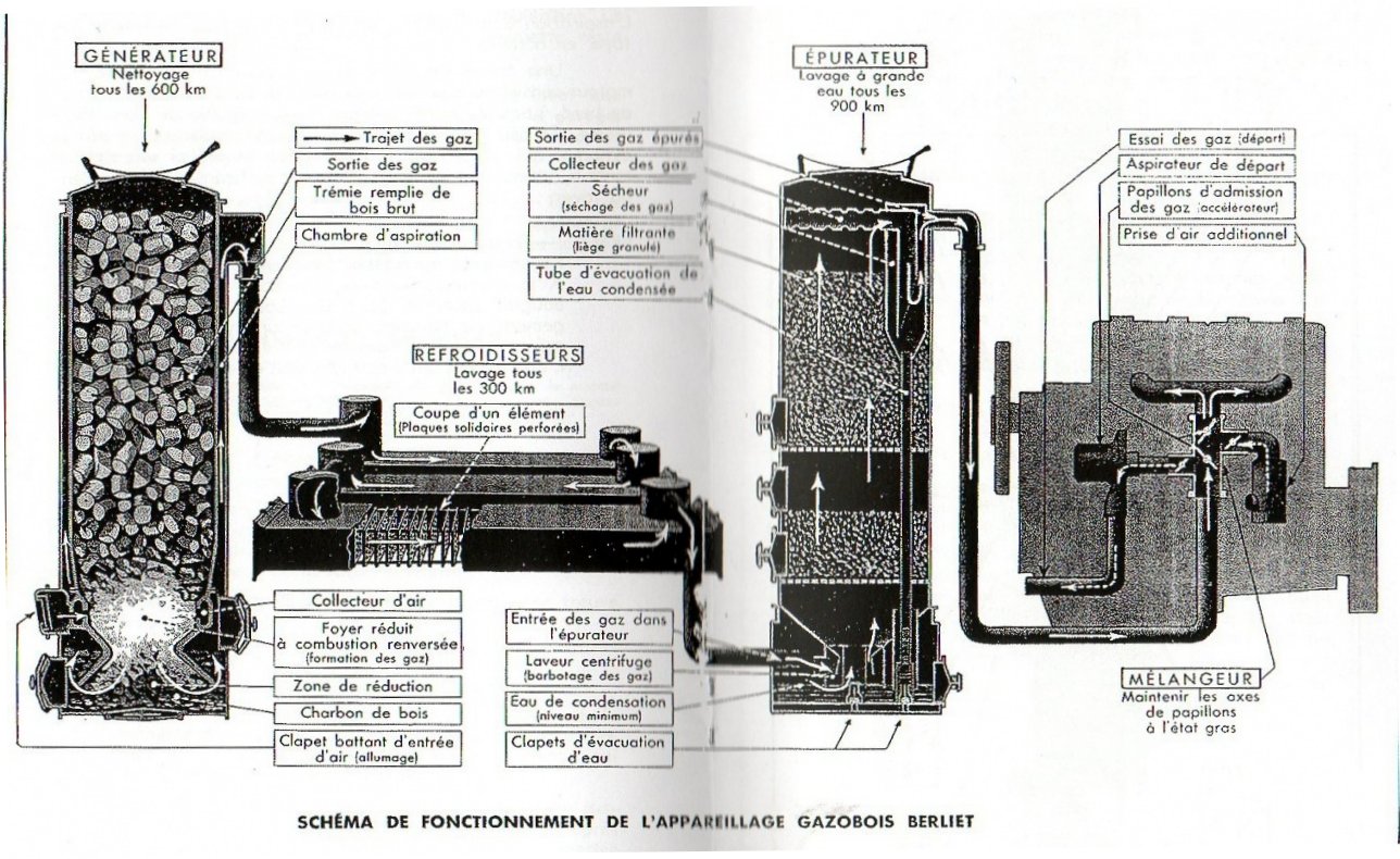
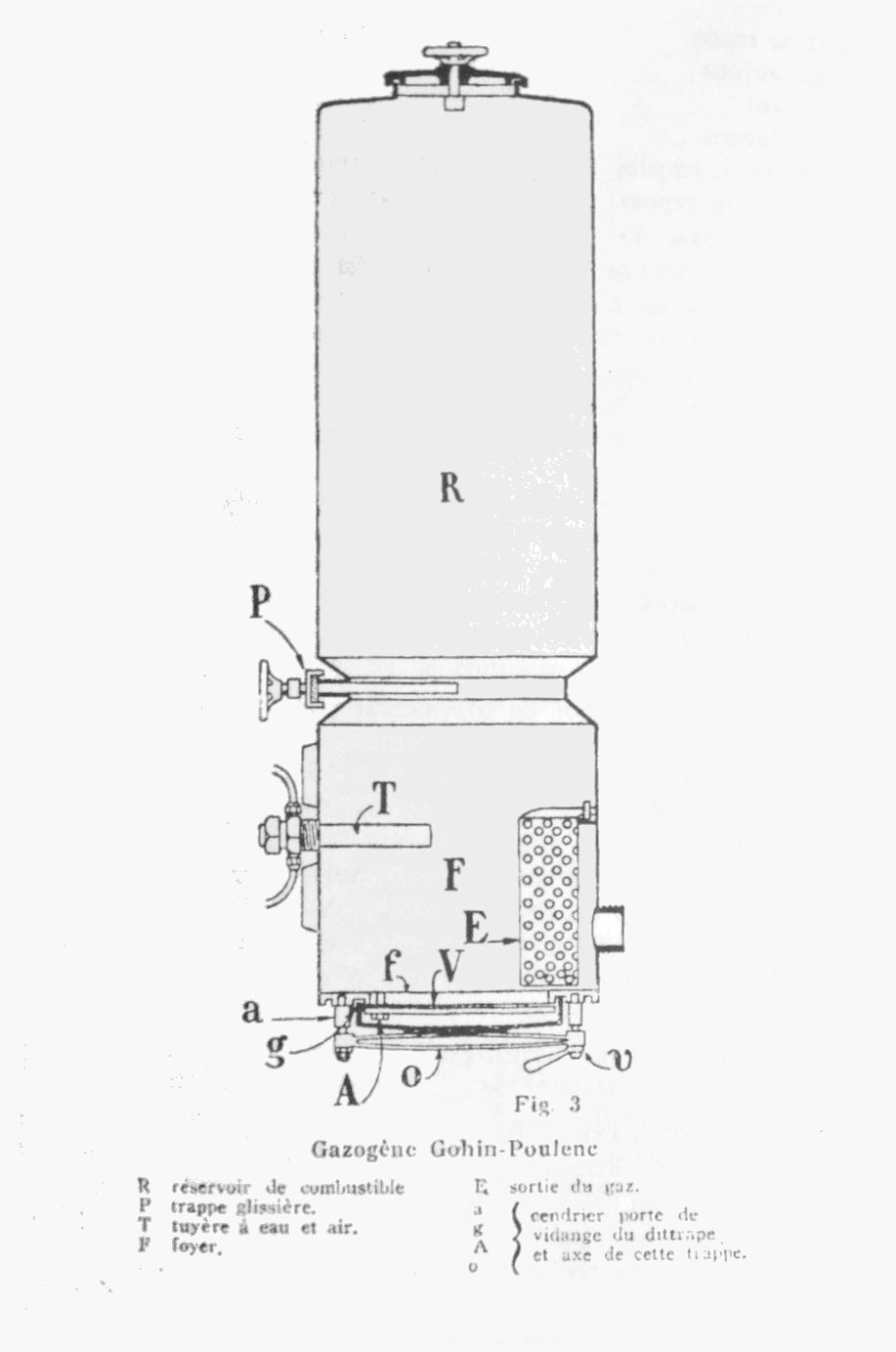
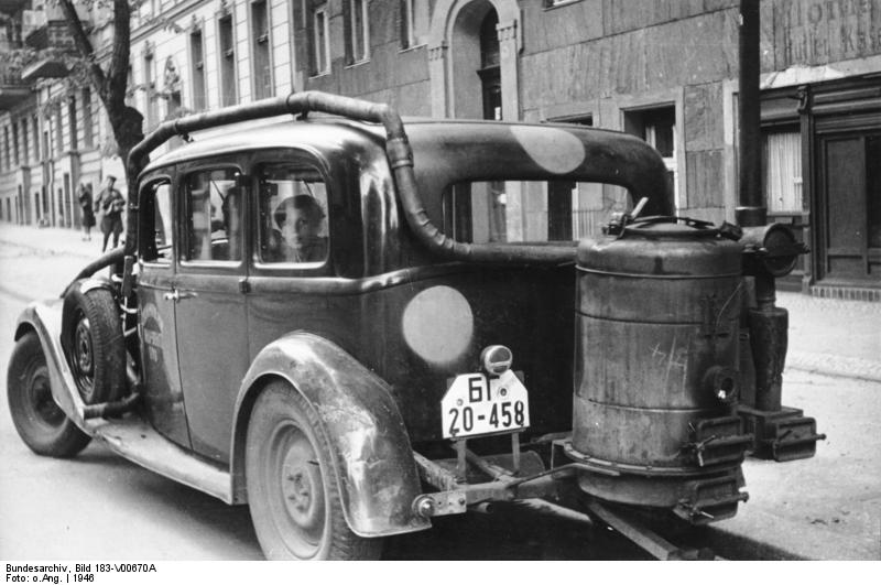
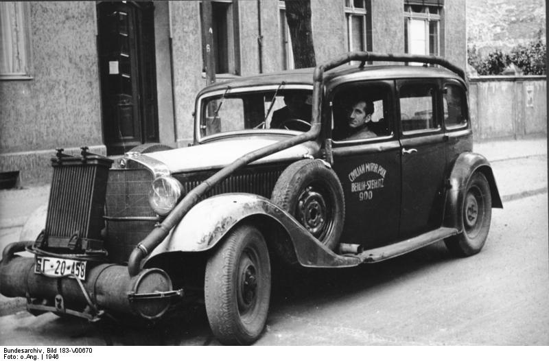
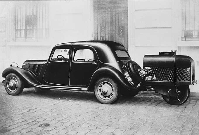
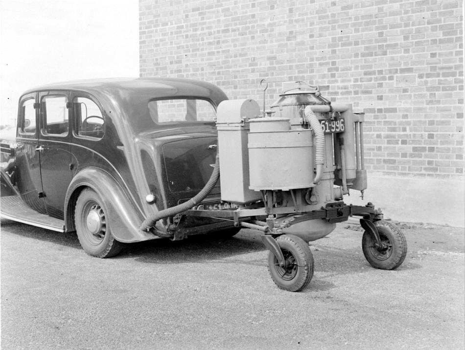
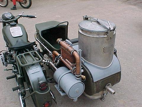
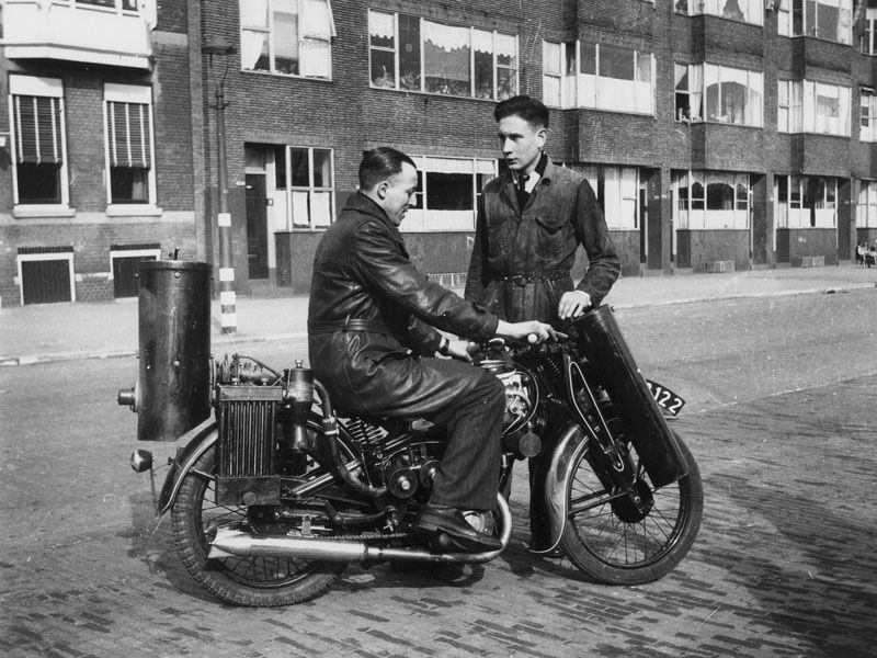
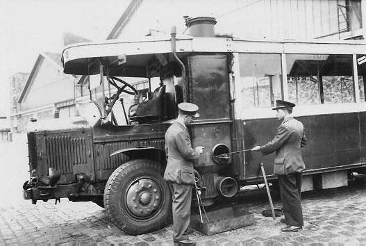
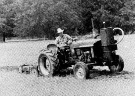
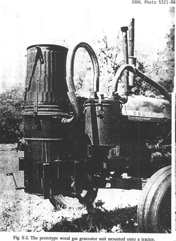
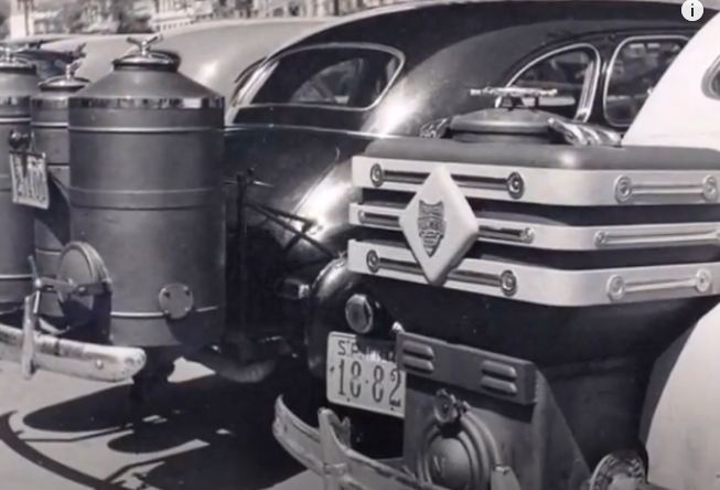
In the 1920s, the French (Not German) engineer Georges Imbert developed a wood-gas generator for mobile use. The wood-gase was cleaned and cooled and then fed into the vehicle's engine. The Imbert gas generator was mass produced from 1931 on. At the end of the 1930s, about 9,000 wood gas vehicles were in use, almost exclusively in Europe.

Left: The Imbert wood-gas generator: 1930

The generator is usually in the form of a tall cylinder. Fuel is loaded in through the lid at top, but only the bottom part of it is burning; that above forms a reservoir of fuel. Ash falls out of the bottom. Air is drawn at the bottom by the suction of the engine.

Most of the tar and other non-gaseous products separate out in the precipitation tank.

The gas is then cooled in a thing looking a bit like a car radiator, for sending hot gas to the engine would reduce its volumetric efficiency. The cooler is placed before the filter to avoid over-heating the filter material, which was usually sisal or felt.

The gas then goes through the filter to remove particulates, then is mixed with air and fed to the engine.

The function of the blower on the right is to draw gas through the system without running the engine when starting the process up. This could be dispensed with if you had a small amount of petrol or kerosene to run the engine while the gas-generator warmed up.

There is a Wikipedia page on wood-gas generators. Looking at those from various manufactuerers below, there seems to be little variation in the basic layout.

This image is the official diagram of the Imbert wood-gas system.

Left: The Imbert wood-gas generator: 1930

This redrawing of the diagram above gives an English translation of the most important parts.

Left: The Berliet wood-gas generator: 193?

Berliet was a French company that manufactured cars, buses, trucks and military vehicles. It was founded in 1899 and was absorbed into Citroen in 1967.

  • A Fuel hopper
  • B Gas collection ring
  • C Inspection and filling door for the charcoal
  • D Air distribution ring
  • E Firebox nozzle
  • F Door for clearing out firebox
  • G Fire box
  • H Swinging valve for air-entry (non-return valve)
  • I Gas outlet
  • J Closure of the refilling door
  • K Gas collection space
  • L Exterior casing of the firebox
  • M Safety-valve spring
  • N Filling-door handle

Above: Berliet wood-gas generator and purifying system: 192?

This generator is shown using wood rather than charcoal. Of interest are the various cleaning (nettoyage) intervals shown; keeping an installation running is going to be hard work.

Note that fully two-thirds of the equipment is just cleaning the gas to make it usable. This seems to be an inherent snag with wood-gas systems. The fuel is here shown as wood rather than charcoal.

Left: The Gohin-Poulenc wood-gas system: 193?

The Gohin-Poulenc system operated in much the same way as the Imbert system, but there was no separate gas cooler. The filter is much larger and may have caused sufficient cooling itself.

  • Melangeur Mixer (of gas and air)
  • Boite de poussière literally Dust Box. Does the job of the precipitating tank

Gohin-Poulenc was a French company. There is no Wikipedia page.

On ABE there is a copy of the operating manual for sale. In French, naturally.

This is the best version of this diagram I have been able to find; even after image processing the small text hovers on the brink of legibility. If anyone can come up with a better version I will be very grateful.

In particular I would like to know the function of the stovepipe at the side of the gas generator. I suspect it been have been a chimney involved in the starting-up process.

Left: The Gohin-Poulenc wood-gas generator: 193?

  • R Fuel hopper
  • P Slide-valve for controlling fuel flow
  • T Inlet for water and air
  • F Firebox
  • E Gas outlet
  • a g A 0 Parts of the cleaning-out door

Clearly the Gohin-Poulenc system included water injection to generate hydrogen.

Left: The Renault wood-gas generator: 1924

This system included water injection to generate a small amount of hydrogen; it also inject water into the carburettor. Note that 60 litres of water are carried in a tank.

An interesting feature is the heat-exchanger (rechaffeur) which heats the incoming air with the hot gas leaving the generator. This seems like an excellent idea but no other system found so far has one. A hand-operated blower provides air for starting.

On leaving the heat-exchanger the cooled gas goes through the dust-remover (depoussiereur) composed of metal grillles, then the scribber in which the gas is wasked with water or oil. The final item at left is a centrifugal scrubber (epurateur centrifuge) which with use of water somehow did a final cleaning of the gas. Note the water trap, (purgeur d'eau) for removing used water. There is some info on centrifugal scrubbers here.

Source: L'Illustration for 23 Feb 1924. There is more about L'Illustration in the French Wikipedia. (in french)

Left: The Malbay wood-gas generator: 193?

  • A Firebox
  • B False hopper (cone to deflect gas)
  • C Fuel hopper
  • D Air inlet
  • E Deflector to prevent ashes from falling into the air inlet
  • F Movable plate controlled from outside to control the air supply
  • G Rod controlling moveable plate
  • H Door for replenishing charcoal (seems in the wrong place)
  • I Door for removing ashes
  • K Partition

One of the wood-gas locomotives below is fitted with a Malbay gas-generator.

Malbay generators are known to have been in use in 1925, but the date of their first introduction has not yet been found. They were based at: La Societe Anon d'Exploitation des Procedes Malbay, 1, Rue BilIant, La Courneuve, Seine.

Left: The Brandt gas-generator:

The Brandt generator drew in air down a central annulus that surrounded a 'reduction column hopper' whatever that may have been. Were there two kinds of fuel, or was the reduction column some sort of purifier?

  • tremie de colonne de reduction = reduction column hopper
  • foyer en acier special = firebox of special steel
  • garnissage refractaire = refractory lining
  • bouchon d'allumage = ignition plug (a port rather than a spark-plug)
  • grille mobile = moving grid (to control combustion)
  • cendrier = ash pan

Left: The De-Dion gas-generator:

This looks very similar to the Brandt generator just above. This one draws in air down two central annuli; cooling air and combustion air. There are separate hoppers for wood and charcoal, the latter resting in a central column hopper, and the gas filters up through it. Here there definitely two kinds of fuel.

Left: The De-Dion gas-generator:

This automatic regulator was used when the De-Dion system was applied to locomotives. They often had lengthy waits at stations, with no draught on the gas generator, which could cause it to go out. The regulator measured the pressure inside the generator with a flexible membrane. At the left the generator is working so the pressure in it is low because the engine suction, and so valve M is open and N closed. At the right the generator is idling and so its pressure is near-atmospheric and the spring (ressort) closes M and opens N, allowing water vapour to be sucked out by the centrifugal fan and maintaining combustion.

Left: The Sabatier-Decauville gas-generator:

According to the text beneath the diagram, this gas-generator used partial recirculation of the gases generated. The details are at present obscure.

Left: The Rustic gas-generator:

Here the Naming of Parts is rather less satisfactory than for the others, as the annotation of the original document seems to have gone wrong. For example, the chimney C was labelleled 'firebox'.

  • A: Refractory material
  • B: Air inlet
  • C: Chimney
  • D:
  • E:
  • F:
  • G: Valve
  • H: Valve

The Rustic was supposed to work on softwood chips or coke. It claimed to idle and restart well.

Left: The Facel gas-generator:

The Facel systen had gas-generator, cooler and purifier in one compact unit.

  • 1: Firebox
  • 2: Air inlet
  • 3: Zone of carbonisation
  • 4: Tuyere
  • 5: Double skin
  • 6: Fuel hopper
  • 7: Gas outlet
  • 8: Cooler
  • 9: Labyrinth cooler
  • 10: Gas outlet
  • 11: Gas outlet to engine
  • 12: Filter
  • 13: Filter grille
  • 14: Flame arrester
  • 15: Condensed water
  • 16: Heater
  • 17: Air circulation space
  • 18: Zone of cracking
  • 19: Ash removal hatch
  • 20: Outer casing of firebox
  • 21: Valve (water drain?)

Left: The Facel gas-generator:

This is the only time a gas-generator system has been seen mounted on the front of a car, though it is only a drawing. I would have thought that all that weight would have required the front suspension to be beefed up, and even then the handling would be badly affected.

It looks like you have to repostion the headlights.

Left: The Facel gas-generator:

Advertisment showing the Monobloc 441 gas-generator system mounted on the front of a ghostly caterpillar tractor. Pour les vignerons = 'For the wine producers'.

Left: The Humboldt-Deutz gas-generator:

The Humboldt-Deutz gas-generator had an adjustable conical deflector so the rate of gas production could be matched to the requirements of the engine..

  • A: Fire box
  • B: Air inlet nozzle
  • C: Shaking grate
  • D: Handle for shaking the grate
  • E: Conical deflector (adjustable)
  • F: Inspection door
  • G: Ash removal door
  • H: Fuel hopper
  • K: Collector pot for condensed water and tar, with drain valve

The design is very similar to the other gas generators.

Left: The Humboldt-Deutz gas-generator system:

The Humboldt-Deutz gas-generator was allegedly intended for tractors which drew a relatively steady gas demand. The diagram shows a heat exchanger where the outgoing gas heats the incoming air; the Renault sytem (see above) also had a heat exchanger. Judging by the arrows for gas flow direction, it looks as if the centrifugal blower is connected backwards.

  • 1: Gas generator
  • 2: Fuel hopper
  • 6: Lid of hopper
  • 14: Centrifugal blower
  • 16: Heat exchanger
  • 18: Gas filters
  • 21: Gas/air mixer
Top right is the gas cooler and precipitating tank


WOOD-GAS POWERED CARS

Left: Car with wood-gas generator: Berlin 1946

Note there are at least three doors for removing ash and other deposits from the system. This was a high-maintenance set-up.

The make of car has not yet been identified.

Photograph from the German Bundesarchiv.

Left: Car with wood-gas generator: Berlin 1946

The words on the door say: 'Civilian Motor Pool, Berlin-Steglitz, 900'. Steglitz is an area of the Steglitz-Zehlendorf borough in the south-west of Berlin,

The pipe running from the back of the car goes into a cylindrical tank at the front which corresponds with the 'precipitation tank' in the diagram above; note that the pipe does NOT run through the car interior, as even a small leak of carbon monoxide would have been very dangerous. The pipe appears to be about 80 mm in outside diameter, indcating that quite a lot of gas had to flow to run the engine. After the precipitation tank the gas goes into the cooler mounted just above it and in front of the usual radiator. This will clearly effect the efficiency of the real radiator, but I assume that given the low calorific value of the fuel, reduced engine cooling was not a problem.

Photograph from the German Bundesarchiv.

While the use of wood-gas allowed transport without petroleum, it was something of a desperate expedient. There were disadvantages:

  • The extra equipment was bulky and heavy, adding considerably to a vehicle's weight
  • It was also considered unsightly.
  • Wood-gas has a low calorific value of about 5.7 MJ per kg, as opposed to 44 MJ per kg for petrol and 56 MJ per kg for LPG. Hence the need for relatively large gas generators.
  • As a consequence of this, range is very limited. In a modern wood-gas car (and they do exist) 30 kilograms (66 pounds) of wood will take you 62 miles.
  • The generator had to be refueled roughly every hour.
  • Starting from cold took at least ten minutes.
  • The carbon monoxide content meant that a gas leak into the car interior could be very dangerous.
  • Particulates remaining in the wood-gas could increase engine wear.
  • There was a good deal of extra maintenance, such as emptying the ash hopper and cleaning the gas cooler and filter.

Left: Car with gas generator on trailer: 1943

The gas generator was sometimes mounted on a one or two-wheel trailer; this neat installation appears to have a one wheel trailer.

Location unknown, but the building behind suggests France.

Left: A stylish Panhard gas generator trailer: 193?

For the more demanding wood-gas customer.

The fuel is stored in the hopper above the round combustion chamber. The tubular chassis had the gas passing through it for cooling and tar deposition.

Left: A stylish Panhard gas generator trailer: 193?

This looks like a posher version of the trailer above. Note the spare wheel- very necessary if the trailer wheels are not of the same size as those of the car.

Left: Panhard gas generator trailer internals: 193?

  • A: Tubular chassis used for cooling and tar deposition
  • B: Firebox
  • C: Purifier (filter) after cooling in chassis
  • D: Chimney for use when lighting up? (Lit: nozzle)
  • E: Gas outlet pipe
  • F: Hopper seal
  • G: Towing point

Left: Mercedes 230 car with gas generator: 194?

A very neat installation in a kind of bustle on the back of the car. The word sauggasanlage means 'suction gas system'.

Generator-kofferraum geoffnet means 'Generator trunk open'. In Great Britain we say boot not trunk.

Location unknown, but it looks like the courtyard of a big mansion.

Left: Car with gas generator on trailer: 1943

This gas generator in Victoria, Australia, is mounted on a two-wheel trailer. The trailer frame appears to be rigidly fixed to the back of the car, and is supported by two castoring wheels.

The large cylindrical gas generator is in the centre of the trailer. Nearest the camera is the precipitation tank, and at the extreme right part of the gas-cooler can be seen. The box with the round top to the left of the generator is the filter. The gas pipe to the engine runs under the car.

Left: Gas generator cantilevered from the back of the car: WW2

Refuelling a gas generator in Australia; note that the chap on the left can hold a sack-full easily with two hands which indicates charcoal rather than the much denser coal or anthracite. The masks are presumably to protect against dust, as they would certainly be useless against any residual carbon monoxide hanging about.

The extra weight on the rear wheels may have made the car's handling a bit problematic.

Left: Unknown car with gas generator: 194?

A very neat installation in the rear.

Left: Car powered by straw gas generator: 1918

This experimental car was built by an engineering professor at the University of Saskatchewan in Canada. The gas was generated by heating straw in retorts with air excluded. Note the very neat design of storage balloon and the pipe running from the front of it to the engine. The car was a converted 1918 McLaughlin tourer.

This vehicle could be described as either a wood-gas (straw-gas) car or as a stored-gas car. There is a YouTube video of a replica straw-gas car at the Western Development Museum in Saskatchewan. It does not run on straw-gas, because the gasbag is made from "layers of styrofoam and glue".(January 2013) See here. (page 24)

Straw gas may not have made much impact on the car industry but it is still very much a thing; see here.


WOOD-GAS POWERED MOTORCYCLES

Left: Motorcycle with wood-gas generator: modern

This appears to be a modern construction. The motorbike looks like a converted BMW R71; the petrol model was produced from 1938 to 1941.

The combustion chamber is mounted neatly at the rear of the sidecar. The grey horizontal cylinder next to it is probably the filter, because there appears to be a pipe running from it to the engine, and the copper pipes above are the gas cooler.

When I stumbled across this machine, I thought it must be a one-off. How naive! If you do a Google image search on 'wood gas motorcycles' you will find at least 15 different machines, many of which are modern.

Left: Sperco-II wood-gas generator for light motorcycles/mopeds: 1941

This looks as if it is the minimum size of wood-gas generator practicable, producing only enough gas to propel a light motorcycle/moped with only one rider. The only version of this system I am aware of had a very modest 98cc engine.

The Swedish Asbrink Company produced this system in 1941. It was designed to run on charcoal rather than wood pellets; the charcoal had to crushed to 5-15 mm in size, and apparently refueling was very complicated. In theory you could drive about 10 km (6 miles) on one refueling, which is hardly a practical proposition for transport even if you are desperate. A plain bicycle would probably be a better idea.

The generator turned out to have a lot of operating problems, and the manufacturer received many complaints, especially of low power. In addition, the Swedish state stopped delivering lubricating oils to civilians, which the two-stroke engine needed, and sales therefore ceased completely. Of 1000 units built, 500 had to be discarded from Asbrink's stock, in addition they took back hundreds of units from their dealers. The project was a disastrous failure.

Note that this motorbike/moped has pedals- they were important, not just because of a general lack of power, but because the rear wheel had to be rotated while on its stand to run the fan for starting-up.

Left: Sperco-II wood-gas motorcycle: 1941

From Rolf Barry Berg:

"My Sperco II is an inheritance from my grandfather who bought it from Sweden during the war, ie in 1942. It is completely original and fitted with a 1936 Blixt 98 cc that was produced at Nymans Verkstäder in Uppsala. I've run it on several veteran rallies both in Norway and Sweden and it works well. It is probably a Speco II in Sweden and mine is the only one in Norway. A piece of Swedish history has been lost here! The permit has number 257"

Left: Sperco-II wood-gas generator: 1941

Today there are only 2 known specimens in Sweden and only this one in Norway. This copy is from 1941 and has production number 206. The generator is complete and completely original.

Note the handy fire extinguisher on the parcel carrier.

The Norway machine is in this Museum.

Left: Close-up of the Sperco-II wood-gas generator: 1941

The purpose of the flanged connection under the label is not currently known.

Left: Fittings of the Sperco-II wood-gas generator: 1941

On the left is the centrifugal fan used for drawing air through the generator when starting-up.

On the right is the device for mixing the wood-gas with air. The small pipe is for adding lubricating oil to the mixture.

Left: Close-up of the Sperco-II wood-gas generator: 1941

This is the Sperco-II in the Motala Museum in Sweden. The round green thing just left of centre is the centrifugal starting fan. When starting the bike was put up on its stand, and the knurled wheel was pressed against the rear tyre (like an old-fashioned lighting dynamo) and was driven when the pedals were turned. Once the system was up and running, the fan drive was swivelled away from the tyre.

Left: The Sperco-II wood-gas generator: 1941

This is the Sperco-II on the Asbrink stand at a wood-gas exhibition held in Stockholm in 1941. Note the rear-wheel stand which allowed pedalling to get the fan running and the charcoal well alight.

Image source: Bilder i Syd image archive

Left: Italian motorcycle with wood-gas generator: 1942

This is presumably something called the Casti wood-gas system; nothing has been found so far except for this image.

Left: Dutch motorcycle with wood-gas generator: 194?

Left: French motorcycle with wood-gas generator: 1944

The gas generator is mounted in the sidecar on the left. Pictured in Périgord in 1944.

Left: USA motorcycle with wood-gas generator: 1981

Nothing has so far been found about this project except for this image with its caption.


WOOD-GAS POWERED BUSES & LORRIES

Left: London bus with gas generator on trailer: WW2

The corrugated combustion chamber is at the rear of the trailer. The horizontal cylinders are for cooling and tar precipitation. The vertical cylinder at the front of the trailer appears to be the filter, as the pipe to the bus engine emerges from it.

A Pathe film of this bus in action can be seen here; there is no sound. The second half of the film shows some wood-gas lorries and some other trailer designs.

I am told the bus is an AEC Regent III RT, registration number GF 440. There is more info on this bus at Wikipedia.

The tower visible in the distance across the Thames belongs to St Thomas' hospital. This locates the bus on the Victoria Embankment, on the west side of the Thames.

Left: Bus with gas generator: date unknown

This wood-gas bus is being cleaned out and refueled. A rather more compact installation than pulling a trailer.

Location unconfirmed but believed to be in Paris. Note steering-wheel on the left.

Left: German army lorry with gas generator: WW2

Note the safety-grid at the bottom of the generator to prevent passers-by getting burnt.

Location unknown at present


WOOD-GAS POWERED TANKS AND HALF-TRACKS

Left: Panzer-I with wood-gas generator: 1939

The Panzer-I tank was built in Germany in the 1930's. After the invasion of Poland in September 1939, the type was clearly obsolete because of its thin armour and light armament. Some were sent to secondary fronts, but others were assigned to panzer Fahrschules (driving schools) for training.

The gas generator is the big round thing at the left; just to its right is the gas cooler, looking rather like a conventional car radiator.

Left: Panzer-II with wood-gas generator: 1940

The Panzer-II tank was considered obsolete after the fall of France in 1940, and some were issued to panzer schools for crew training. Petrol was already in short supply at that point in the war, and so some Panzer-IIs were converted to use wood gas. (holzgaz in German)

The gas generator is the tall vertical cylinder at the back. The horizontal tubes were for tar precipitation and cooling the gas before it was fed to the engine.

This may have been effective engineering, but I don't think anyone could claim it was elegant.

Location: Yugoslavia 1945, after Soviet capture.

Left: Panzer-II with wood-gas generator: 1940

Another view of the Panzer II with wood-gas generator.

Location: Yugoslavia 1945, after Soviet capture.

Left: Half-track with wood-gas generator: WW2

This half-track has the same type of wood-gas generator as the Panzer-I above.

I am no expert on armoured-vehicle recognition, but I think this is a Sd.Kfz.251/1 type Schützenpanzerwagen. (Armored personnel carrier) They were the most numerous German half-tracks of the war; over 15,000 were built.

The Sd.Kfz.251/1 has a Wikipedia page.


WOOD-GAS POWERED TRACTORS

Left: Cultivator/tractor with wood-gas generator: 193?

This cultivator is equipped for wood-gas operation. The gas cooler can be seen in front of the gas-generator and purifier.

There is a clearly visible hand-cranked centrifugal blower for starting.

Nothing is currently known about this image, but I am inclined to think it comes from Italy.

Left: Fiat tractor with wood-gas generator: 1941

The gas-generator is on the right, with the fuel hopper on top and a centrifugal blower attached to it.

The photograph was taken on 28 May 1941 in Turin, Italy. Fiat was based in Turin.

Left: Tractor with wood-gas generator: 1989

This woodgas tractor (a converted John Deere) is on test in the USA.

The design work was done in 1989 by the Biomass Energy Foundation and Oak Ridge National laboratory, as a precaution against possible future petroleum shortages. The gas generator was an improved type compared with WW2 designs, using "stratified, downdraft gasification".

Left: Tractor with wood-gas generator: 1989

This is a close-up of the woodgas tractor above.

The top of the gas-generator looks very much like a repurposed dustbin.


WOOD-GAS VEHICLE VIDEOS

Left: Wood-gas WW2 vehicle video: uploaded 2017

This video on YouTube has many images of WW2 wood-gas vehicles but they just fade from one to another with no soundtrack or other information.


WOOD-GAS POWERED LOCOMOTIVES

Wood-gas locomotives were to a large extent a French enterprise.

The first application of woodgas in commercial service took place from 1908 to 1910, on an experimental bus with gasifier which served the Montmartre - Place St Michel line. (Line 21 nowadays)

Left: Locomotive with wood-gas generator: France 1936

France had a large number of minor railways, most of them marginally profitable at best. This may have been an attempt to reduce fuel costs, or a precaution against petrol shortages in a war that looked increasingly inevitable. Probably both.

There is a reference to a moteur sans soupapes Panhard, ie a valveless motor. This turned out to be not a two-stroke engine, but a sleeve-valve engine, the first version of which was produced in 1910. Charbon de bois is wood charcoal.

Left: Railcar locomotive with integral wood-gas generator: France 193?

Two pipes lead from the gas generator over the roof of the railcar.

Left: Locomotive with towed wood-gas generator: France 193?

This seems like a very clumsy set-up. Pushing the gas-generator trailer in front of the locomotive would probably be impractical as it would derail, so it would have to be moved from one end to the other at each terminus.

Left: Standard Ansaldo ALn 56 railcar: Italy 1936

This is the standard version, which was powered by a V8 Diesel engine mounted under the floor.

Thanks to Paolo from Trieste for drawing this locomotive to my attention.

Left: Standard Ansaldo ALn 56 railcar: Italy 1936

Shortly after the standard ALn 56 railcars were ordered, three experimental versions with a wood-gas supply was also ordered; (on 27 August 1936) these were ALg 56.401-403.

They were based on wood-gas generators built by the Tallero Officine Elettroferroviarie company of Milan. The generators could deal with about 300 kg of charcoal at a time, loaded from the top by use of an external ladder. It sounds as though refueling would be hard work. A compartment below the floor stored another 600 kg of fuel.

The cubic capacity of the V8 was increased to 21.551 cm³ (21 litres) by using larger diameter cylinders, to compensate for lower calorific value of wood-gas.

The ALn 56 has a Wikipedia page. (in Italian)

Left: Generator loading hatches of the Ansaldo ALn 56 railcar: Italy 1936

Because of the danger from carbon monoxide, the generator was housed in a vertical trunk and was completely isolated from the passenger compartment.

In Italian, wood-gas is called gas povero, which translates as 'lean gas' or 'poor gas'.

There was a purifier at each end of the railcar near the driver's seat, in a compartment where a suction electric fan was installed. There was also a constant level water tank, a gas/air mixer, and a downward ejector of the residual combustion slag. The gas, washed and filtered, then reached the engines.

Externally the locomotive was asymmetrical: the side carrying the gas generators had air intakes in an almost central position, with the fuel loading ports at the top, and at the left end was an access door to the purifier protected by a shutter ventilation. The opposite side had only the access door to the other purifier on the left end.

Left: Badoni woodgas locomotive Tipo IV: Italy 1942

In 1942 an 0-4-0 wood-gas prototype locomotive was built, based on the Type IV shunting engine. This drawing shows a design study by Badoni and SOTERNA which is believed to be close to the 1942 prototype. The Badoni company was based at Lecco, in northern Italy. The Badoni company still exists today.

The vertical gas generator is mounted behind the central cabin; just ahead of the cabin are two vertical purifiers. The gas cooler can be seen at the front. (left)

Final drive was by chains to each axle.

Thanks to Paolo from Trieste for drawing this locomotive to my attention.

Left: Badoni woodgas locomotive Tipo IV: Italy 1942

This shows the gas cooler at the front, and the purifiers at each side.

Thanks to Paolo from Trieste for drawing this locomotive to my attention.

Left: Badoni woodgas locomotive Tipo IV: Italy 1942

This plan shows the central mounting of the gas generator and the supply pipe running forward on one side of the locomotive. The pipe into the engine is at top left, and next to it is what appears to be a small centrifugal blower for starting up.

Thanks to Paolo from Trieste for drawing this locomotive to my attention.

Left: French Nord woodgas locomotive: 193?

There were several designs of woodgas locomotive built for the French railway networks in the 1930's.

This wood-gas locomotive is very similar in concept to the Badoni locomotive above. No information on this particular design has been found so far.

Left: French woodgas locomotive BDR No 172: 1935

Shunting locomotive on the Etat network in 1935.

It is fitted with a Malbay gas-generator. (see above)

Left: French Renault UV woodgas locomotive n° 389.: June 1942

Gas-generation by Gohin-Poulenc; it looks as if there two generators. Note the horizontal gas-coolers on the roof.

Left: French Renault JJ woodgas locomotive: 1935

Shunting locomotive with two gas-generators (of unknown type) installed. The gas cooler is on the roof again; pretty much the obvious place to put it.

Left: French Renault JJ woodgas locomotive: 1935

Shunting locomotive having its gas-generator (of unknown type) installed.

Left: French woodgas locomotive: 193?

This locomotive used the De-Dion wood-gas system described above. A worker can be seen accessing the top of the generator.

Left: Woodgas locomotive: 193?

This shunting locomotive is preserved at the Utrecht Railway Museum in Holland. Their website gives no information, and the Museum's Wikipedia page does not include a wood-gas locomotive in a list of their locomotives. However, that page suggests the picture is of a NS Class 200; these were usually diesel-powered.

No gas-cooling tubes are visible (you would expect them to be on the roof, as in some of the pictures above) so it is likely that some of the wood-gas system is missing.


WOOD-GAS POWERED BOATS

According to an Italian encyclopaedia, a wood-gas motorboat called Pioner (probably Pioneer) was built in England in 1911. No other information has been found so far.

Source: The Treccani Encyclopaedia. (in Italian)


WOOD-GAS POWERED AEROPLANES

You might well think that given the cumbersome appearance of the various wood-gas road vehicles, a wood-gas aeroplane was out of the question. But you would be wrong.

Left: Woodgas aeroplane: 19??

For some reason this article was written in three languages- German, Italian, and French. Unfortunately the size at which it has been reproduced means the text is not quite readable in this image.

The text refers to the seven illustrations as follows:

The sport plane Comte AC-4 flies propelled by wood-gas. 1) The charcoal-based generator is cleaned. 2) 34 kg of charcoal allow for one hour of flight. 3) The Pilot Ernest Wysa (sp?), chief pilot of the K.T.A. is the builder of the apparatus. 4) The gas mix is tested with a pitch-covered torch. 5) The wood-gas is ignited through a small door in the posterior wall. 6) The engine is started... 7) and the first wood-gas airplane in the world takes off for its first flight.

The Comte AC-4 was a 1920s Swiss two-seat sport/training aircraft produced by Flugzeugbau A Comte.

Thanks to Mathieu Maury for reading and translating the text.


WOOD-GAS WEBSITES

There is much information and many pictures at chevrolet-gazogene-imbert. It is an excellent site.

There is a forum with a lot of pictures at gazogenes.superforum.

See also Drive On Wood


Back to Home PageBack to The Museum EntranceTop of this page