 |
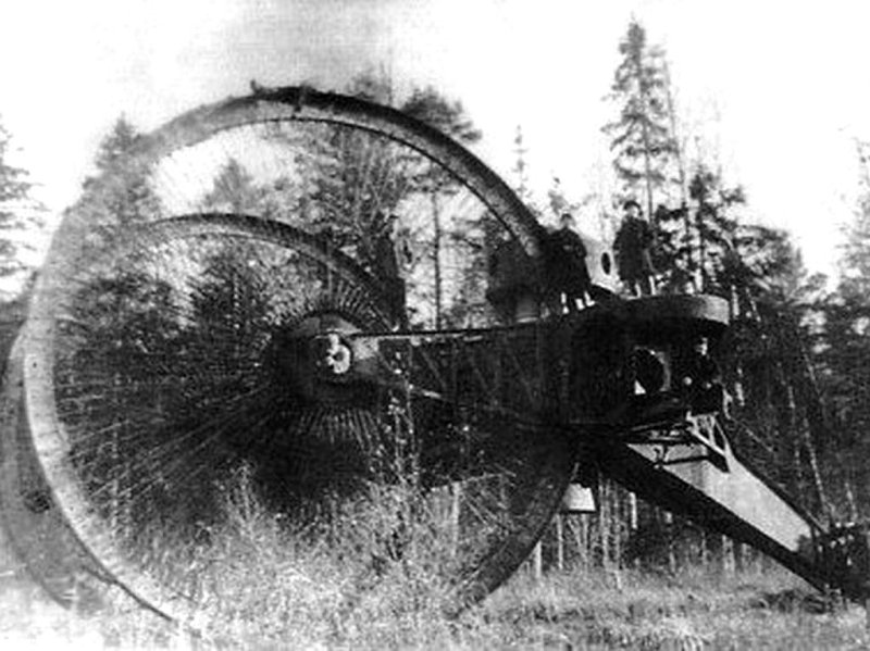
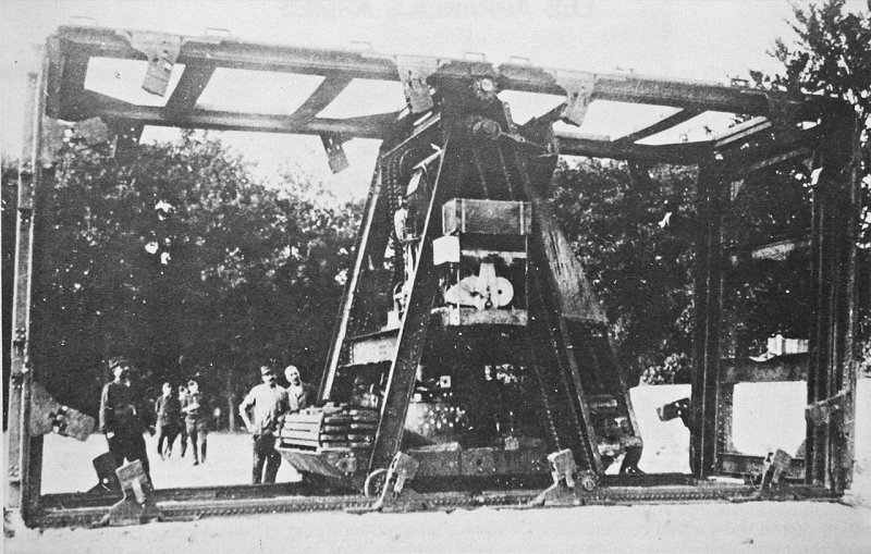
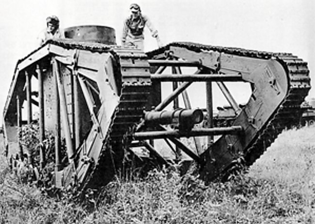
| Left: The Tsar tank: 1915
A tank is normally reckoned to be an armoured fighting vehicle moving on caterpillar tracks. The Tsar tank, developed by Imperial Russia from 1914 onwards, instead used two huge front wheels in a tricycle configuration; the idea was that the enormous wheels could deal with any likely depth of trench. Most tanks like to keep as low a profile as possible, but this was a conspicuous exception. It would have been extremely visible on any battlefield.
The spoked wheels at the front were nearly 9 metres (30 ft) in diameter, but the third wheel at the back was only 1.5 metres (5 ft) in diameter.
Each front wheel was powered by a 250 HP Sunbeam engine. Sunbeam produced a wide variety of aero-engines, and is not currently known which design was used. The likeliest candidate is the Sunbeam Maori, a V-12 giving 250 HP from a 12-litre displacement.
Tests did not go well; the tank was underpowered and the rear wheel was prone to getting stuck in soft ground. The project was abandoned, and the tank was eventually scrapped in 1923.
The Tsar tank has rather brief Wikipedia page.
Apologies for the picture quality. No better pictures appear to exist. Note the two men on top of the tank body and one standing in the sponson, which has no gun mounted. The top turret has apertures for guns but none are mounted.
|
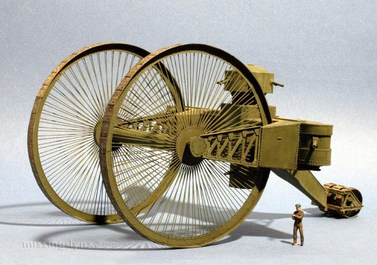 |
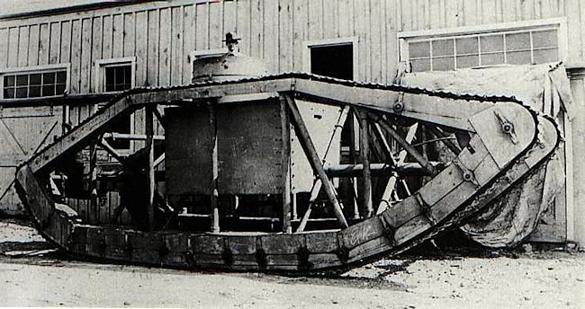
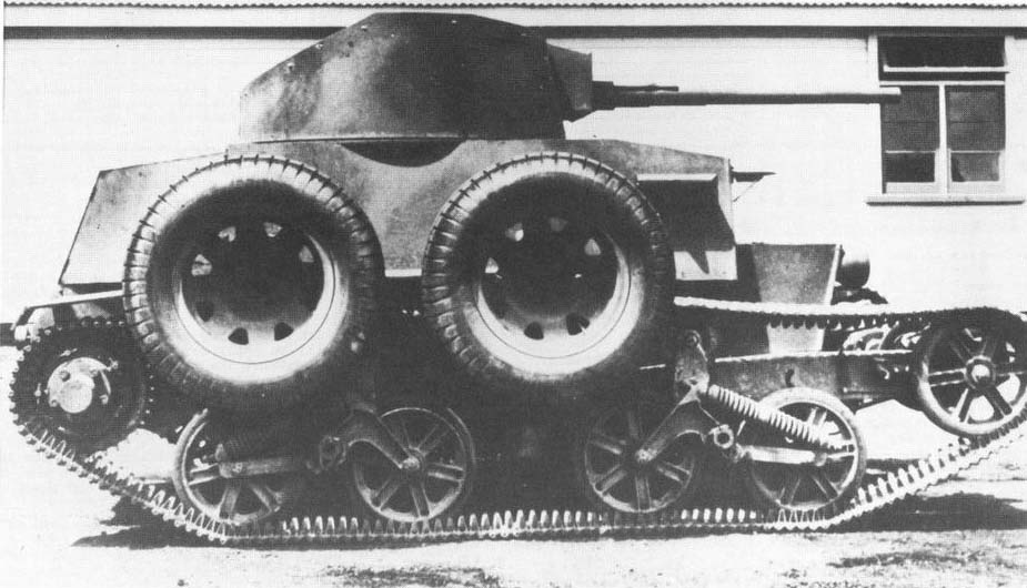
| Left: The Tsar tank: 1915
This image (I am not sure if it is a model or a rendering) gives a much clearer view of the Tsar-tank's construction. There was a circular turret on top of the main body; it appears to have four guns at 90-degree spacing, so presumably did not traverse. The turret is too small to hold a decent-sized gun, and the field of fire is restricted as the turret is below the top of the front wheels.
There is also a turret with at least one gun underneath the main body, with an even more restricted field of fire, and two further guns mounted in sponsons on each side.
|

THE BOIRAULT BRIDGE TANK: 1914
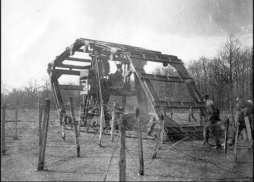 |
| Left: The Boirault Bridge tank Version-1: 1914
This prototype machine stretches the definitition of what is a tank; it is usually just called the Boirault machine. It had one huge track made from girders configured as six giant links that completely encircled the driving machinery inside it. The prototype had a top speed of only 1.9 mph. (3 kph) The arrangements for steering were basic indeed, consisting of a main jack that lifted the whole machine; then it could be turned up to 45� by hand effort from the outside or by a system of smaller jacks controlled from the inside of the machine. It was not a practical evolution under enemy fire.
The Boirault machine has a Wikipedia page.
There is some more info here.
|
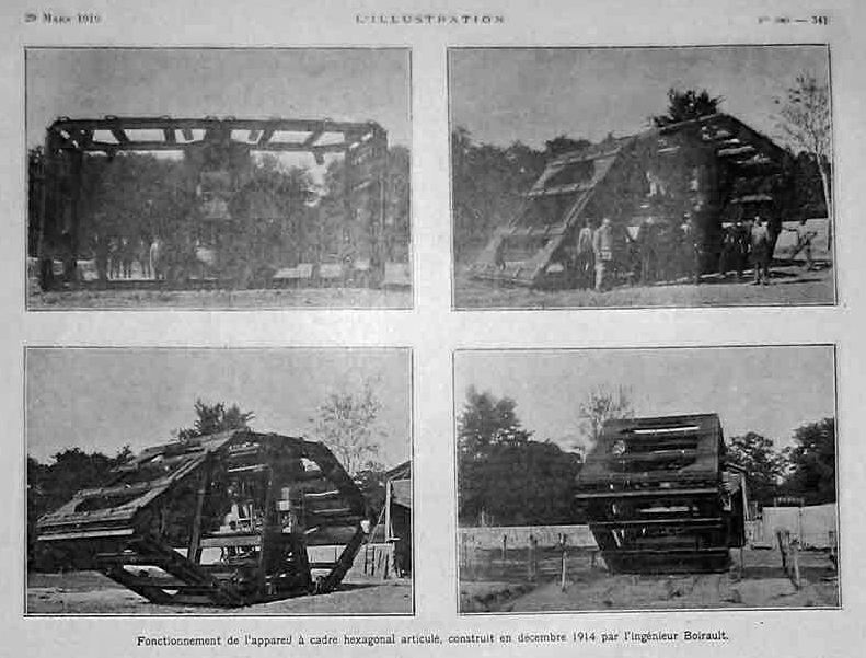 |
| Left: The Boirault Bridge tank Version-1: 1914
This gives a better idea of the construction and operation. The driving machinery was an 80 HP petrol engine mounted inside an A-frame construction.
|
 |
| Left: The Boirault Bridge tank Version-1: 1914
This shows the complicated system of chains that propelled the tank. There appear to be weights added at each side of the A-frame, presumably to increase stability.
There is more info and pictures of the Boirault Bridge tank here.
|
 |
| Left: The Boirault Bridge tank Version-2: 1916
A second version of the bridge-tank was built in 1916 that was lighter and more compact, with armour protecting the engine and the driving compartment. It had some degree of real steering control, but the minimum turning radius was an enormous 100 meters. The speed remained extremely low at 1 km/h. (0.6 mph)
|
 |
| Left: The Boirault Bridge tank Version-2: 1916
As for the first version, power transmission was by chains. The man on the left is believed to be M. Boirault.
After testing, the whole Boirault project was abandoned.
|
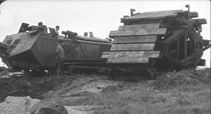 |
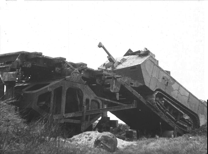
| Left: The Boirault Bridge tank Version-2 in action
There is an excellent video of the Boirault tank (right) on trials here.
Baulks of wood have been attached to the tracks for some reason.
The tank on the left is a French Saint-Chamond tank. This was the second tank introduced by the French and it was not particularly successful, the tracks being too short for the body.
This is a still from the first half of the video.
|
 |
| Left: The Boirault Bridge tank Version-2 in action
Side view of the Boirault tank, showing the drive chains.
This is a still from the video.
|
 |
| Left: The Boirault Bridge tank Version-2 in action
This seems to illustrate why the Boirault machine was sometimes called a Bridge tank; it appears the idea was that if it got into a wide trench other tanks could use it as a bridge to cross the obstacle.
In the video, this attempt to put one tank on top of another was abandoned at about this point. Wisely, in my view; looks a very iffy business.
Now, when one tank loves another very much... No, this is not how tanks make other tanks.
This is a still from the video.
|
THE TREFFASWAGEN: 1917
 |
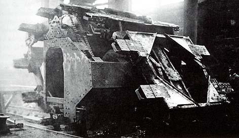
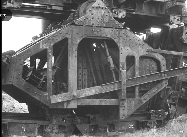
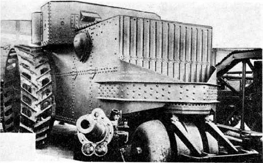
| Left: The German Treffaswagen tank: 1917
The Treffaswagen (which Google Translate unhelpfully renders as 'Treffa's car') was a tank project developed under contract by the Hansa-Lloyd works of Bremen, in parallel with the much better known A7V, which was the only German tank used in combat in WW1.
The prototype was finished on February 1, 1917. It had two 11 ft diameter steel wheels at the front, with a rectangular armoured body between them. The rear wheel was more of a big roller, and was used for steering; it had two smaller-diameter steel wheels on each side, whose porpose is currently unknown; possibly they were to resist the central roller getting bogged. It can just be seen at the right.
The body carried a forward-facing 2cm TUF gun, and on either side was a machine gun that fired through a central hole in the front wheel. They were intended for firing enfilade into trenches. This would have been potentially very destructive, but the Allies were quite aware of the need to build traverses into their trenches to prevent that sort of thing.
The prototype had a crew of four; commander, driver, gunner, and loader, and it weighed 18 tons. Only one prototype was constructed, and thoroughly tested during February and March 1917.
The results were disappointing; the centre of gravity was too far forward and if the front wheels dug into a ditch the tank could flip over onto its back. This actually happened once in the summer of 1917. The Treffaswagen was rejected in favour of the A7V. (Fun Fact: the approximately 50 captured British Mark IV tanks used by the Germans outnumbered the 20 A7V's they produced)
The Treffaswagen has a short Wikipedia page. (in Dutch)
|
 |
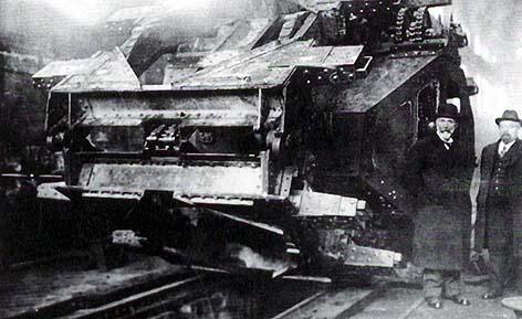
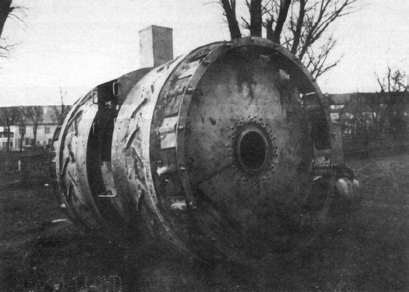
| Left: The German Treffaswagen tank: 1917
The Treffaswagen prototype seen from the rear, with a man to give the scale. Note the two smaller steel wheels on each side of the rear roller, purpose currently unknown.
Maximum speed was 10 km/h (6.2 mph)
|
THE SKELETON TANK: 1918
 |
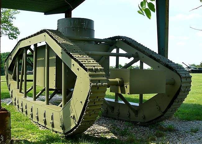
| Left: The USA Skeleton Tank: 1918
The Skeleton Tank was an American attempt to duplicate the trench-crossing abilities of the British rhomboid tanks, in a much lighter and simpler vehicle. The tracks ran around a relatively light frame largely constructed of steel piping, which was easily repaired and. The frame could be dismantled for railway transport. Inside the frame of the 'Skeleton Tank' was a small armoured box holding the crew of two.
The hope was that most shells would pass unhindered through the open frame, though it looks to me as if at least half of the shells coming directly from the side would hit the armoured enclosure.
This is the front of the tank. The armoured box had a gun turret on top and an engine on each side it. The driver had a horizontal vision slit at the front of the box, and the commander/gunner (not a very practical combination of jobs) had a vision slit in the turret.
There is a good deal more information in the Tank Encyclopaedia.
|
 |
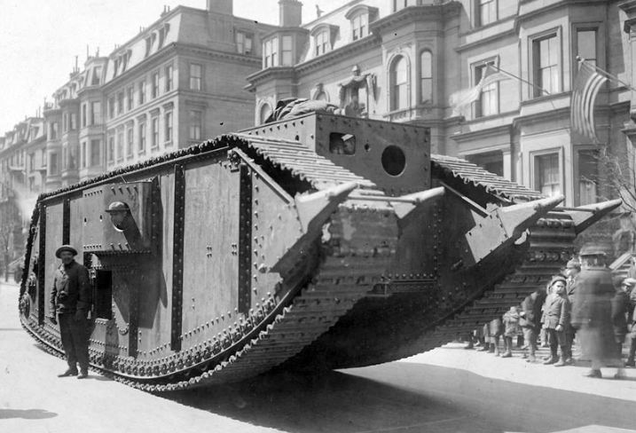
| Left: The USA Skeleton Tank: 1918
Only one example was built, carrying a dummy gun and turret; it was ready for testing by October 1918, but after the November 1918 Armistice development was canceled, along with most other tank development programs. It never saw any active militiary service.
It cost $15,000 to construct the one prototype which is a bit under $250,000 US dollars today.
|
 |
| Left: The USA Skeleton Tank: 1918
The WW1 Skeleton Tank is shown here as it was stored at the US Army Ordinance Proving Grounds, Aberdeen. It has now been moved to Fort Lee.
This is the rear of the tank; the rectangular box contains the transmission gearing.
|
THE US STEAM TANK: 1920
 |
| Left: The US Steam Tank (Tracked): 1918
The Steam Tank (tracked) was an early U.S. tank design of 1918 imitating the design of the British Mark IV tank. There was an earlier version in 1917 called the Steam Tank. (wheeled)
While a steam-powered tank seems like the very essence of Steampunk, it was a not unreasonable decision, driven by the lack of powerful internal-combustion engines. There were two boilers, fueled with paraffin.There were two 2-cylinder steam engines of 250 HP each; each engine drove one track. This gave only a maximum speed of 4 mph.
The British Mark IV tank had a single 105 HP petrol engine.
US steam tanks have a Wikipedia page, but it says little about the steam propulsion machinery.
|
USA STEAM WHEEL TANK: 1918
 |
| Left: The USA Steam Wheel Tank: 1918
The USA steam wheel tank was a steam-powered prototype. (It was also known as the Holt Steam Tank) It had wheels rather than tracks; the two rear driving wheels were 8 feet (2.4 m) in diameter and the front roller (rather than wheel) was 4 feet (1.2 m) diameter and used for steering; this doesn't sound especially adapted to crossing trenches. Some sort of plate was carried in front of the roller, which may have had something to do with trench-crossing.
Each rear wheel had its own Doble two-cylinder 75 HP steam engine and a Doble kerosene-fired boiler. That sounds desperately underpowered for practical use.
The prototype was built in February 1918 and tested between March and May 1918 at the Aberdeen Proving Ground. Its performance was poor and it saw no further development.
There is more information on Wikipedia.
|
THE WHITE STAFF CAR: 1920
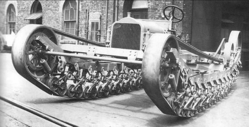 |
| Left: The White Staff Car: 1920
While this vehicle is not strictly a tank, it does have certain tank-like qualities. A staff car is a car used by senior militiary officers for moving about. They were frequently given some off-road capability and often four-wheel drive.
This takes the concept a stage further by perching a car body on top of a hefty set of tracks. The tracks appear to be in the form of a smooth rubber belt, rather than linked metal plates; no doubt it would have been given a tread if it had reached production. This is an example of a Kegresse Track; it was reinforced with steel wire. In the 1920s, the US Army purchased several Citro�n-K�gresse vehicles for evaluation and then purchased a licence to produce them. This led to several US vehicles such as the M2 half-track, which also had a anti-ditching roller at the front. However no fully-tracked Kegresse vehicles have so far been found apart from this one.
|
The picture shows chain drive from the rear axle of the car to the rear roller of the tracks. The tracks look rather complicated; are all those idler rollers really necessary?
Kegresse Track was developed by the French engineer Adolphe K�gresse while he was working for the Russian Tsar Nicholas II.
This vehicle was built by the White Motor Company; note the name on the top left of the radiator. The Museum Staff have so far failed to find any more information. Can anyone help?
THE VICKERS T15 WHEEL/TRACK TANK: 1926
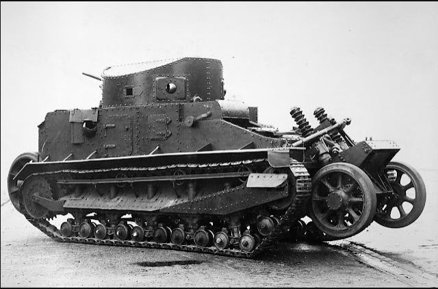 |
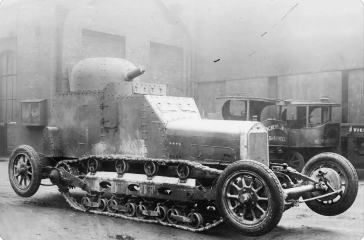
| Left: The Vickers T15 Wheel/Track Tank: 1926
This tank with added wheels was a conversion of a Vicker Medium tank. It was demonstrated at Camberley Common on 6 July 1926. A retractable pair of wheels was fitted at the front and the back; these had a narrow spacing as they were fitted in between the tracks, and cannot have given much stability in wheel mode. When high speed was required, the wheels were lowered and the tracks lifted off the ground; in this mode it was credited with a top speed of 20 mph. Steering was supposed to be done by the front pair of wheels, but it is not currently clear how. There is no sign of brakes on the front wheels.
This is a view of the front of the tank; the turret has been traversed so the gun points backwards. The hinged visor for the driver can be seen below and just to the right of the turret.
|
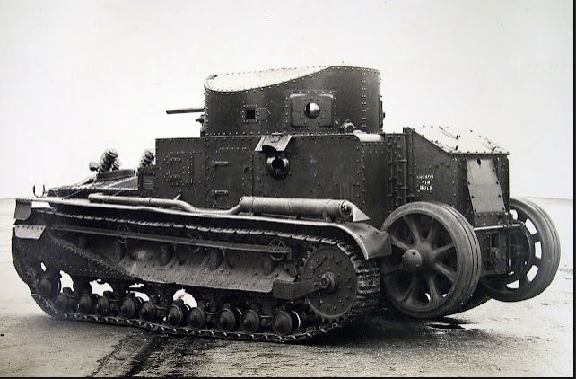 |
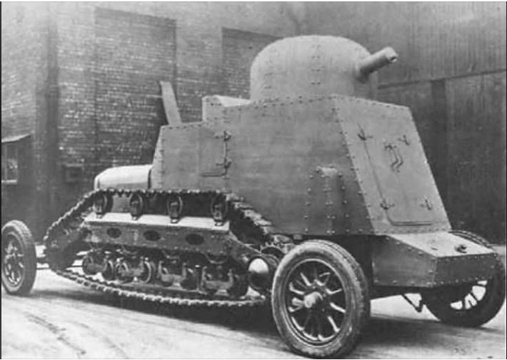
| Left: The Vickers T15 Wheel/Track Tank: 1926
This is a rear view of the T15 tank.
|
THE VICKERS D3E1 WHEEL/TRACK TANK: 1928
 |
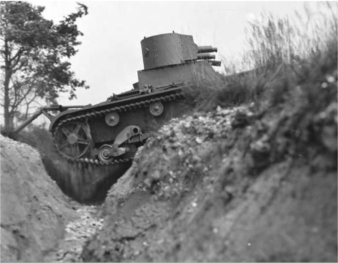
| Left: The Vickers D3E1 Wheel/Track Tank: 1928
This tank was designed primarily to deal with the very limited service life of tank tracks. When the ground was suitable, the tracks were lifted from the ground (the wheels were fixed, unlike in the T15 above) and the tank travelled on the wheels.
This is the front of the tank.
|
 |
| Left: The Vickers D3E1 Wheel/Track Tank: 1928
This is the rear of the tank. The turret (apparently armed with a machine gun) is now pointing backwards. The armour was only 8mm thick, which was common at the time. A crew of four was planned.
The D3E1 was not a success. The wheelbase was too long, making it hard to handle, while the track length was too short, leading to excessive pitching of the vehicle. Development ceased.
|
THE STAUSSLER TRENCH-CROSSING LEG: 1930
 |
| Left: The Staussler Trench-Crossing Leg: 1930
While it is not actually a tank, the Staussler trench-crossing leg is so bizarre it cerainly has a place here. It was a pivoted leg fitted to the front and rear of a tank. This would swing out (apparently actuated by solely by gravity) when the vehicle tilted forwards when starting to cross a trench. The leg would swing out and rest on the ground on the far edge of the trench, providing support beyond the track base of the vehicle. The forward motion of the tank slightly raised the front of the vehicle, until the leading section of the track made contact with the ground and propelled the tank forwards. Apparently the front leg would then automatically disengage with the ground when the tracks took the weight of the vehicle again. The back leg worked in a similar fashion. It is not quite clear how this worked, and there appear to regrettably be no cine film of it in operation. Springs were used to hold the legs in against end-stops when not in use.
The Leg was invented by the Hungarian engineer Nicholas Peter Sorrell Straussler. (1891-1966) He is best known as the inventor of the flotation system used by Allied amphibious DD (Duplex Drive) tanks during World War II, and many other projects including various tanks and tank conversions. Some designs were unsuccessful; one that did not prosper was a main battle tank which had two sets of tracks and a large gun protruding through the glacis (the sloping front of the tank) which foreshadowed the Swedish Stridsvagn 103 S-tank. No prototype was built.
Mr Straussler has an informative Wikipedia page, but it does not mention his trench-crossing Leg.
|
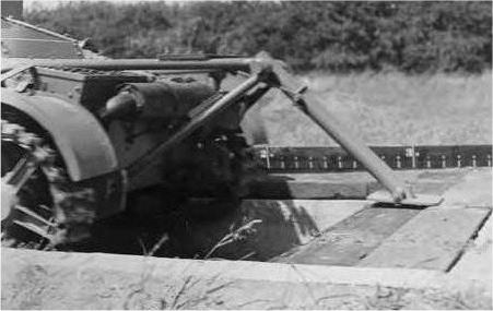 |
| Left: The Staussler Trench-Crossing Leg: 1930
Shown here in the deployed position at the rear of the tank.
|
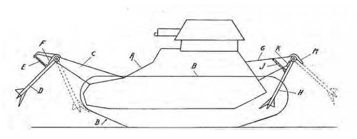 |
| Left: The Staussler Trench-Crossing Leg: 1930
US patent 2,012,090 was secured. A copy has been obtained by the Museum Staff. This diagram is the only one in that patent. Note the Legs were fitted at both front and back of the tank.
|
THE ANSALDO MIAS/MORAS TANKETTE: 1935
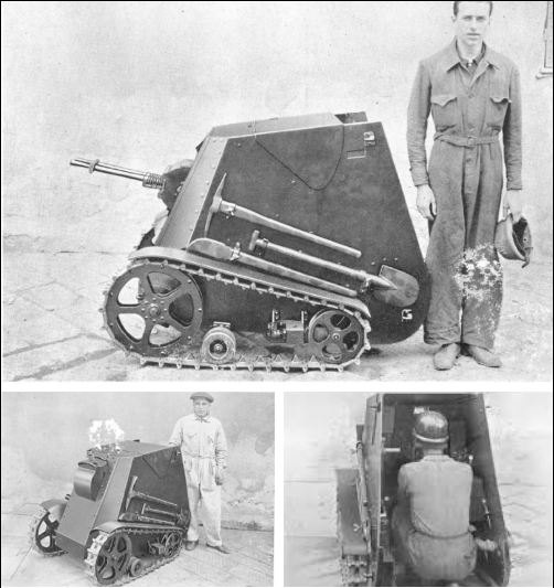 |
| Left: The Ansaldo MIAS/MORAS 35: 1935
The Motomitragliatrice blindata d'assaulto (MIAS) was a one man tracked vehicle built by the Ansaldo corporation in 1935.
It had a 250cc 5 HP engine which gave 5 km/hr forward speed and 2 km/h in reverse. Remarkably there was no seat for the one man crew, thus the crewman had to scuttle about in a crouch to follow the MIAS as it moved. The forward armour was designed to stop German 7.92x57mm Mauser rounds at the front, but the side armour would only stop Italian 6.5x52mm Carcano rounds. This was standard rifle ammunition; any sort of armour piercing ammunition would go straight through. The MIAS was armed with a 6.5mm machine gun with 1,000 rounds.
Ansaldo also built the Moto-mortaio blindato d'assaulto (MORAS), which was the same vehicle, but with the machine gun replaced with the odd 45mm Brixia mortar which used blank rifle cartridges to launch 500 gm high explosive mortar rounds. Fifty rounds were to be carried.
The Italian Army were keen on tankettes, such as the L3/35, which came utterly to grief every time it encountered Matilda: Queen of the Desert. Neither the MIAS or the MORA went into production, the Italian Army rightly declaring it useless for modern warfare.
There is an excellent page on the MIAS/MORAS at Tanks-encyclopedia.com.
|
THE RUSSIAN JUMPING TANK: 1937
A tank that can jump across rivers and other obstacles sounds like a ridiculous proposition. But the Soviet Russians tried it.
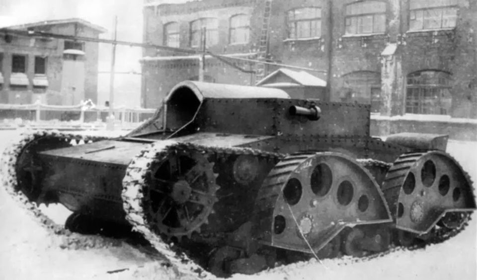 |
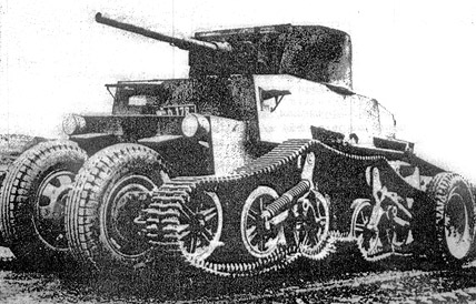
| Left: The TPP-2 jumping tank: 1937
The following quoted text comes from "Report on the trials of the TPP-2 vehicle", confirmed by Barykov 1938, Leningrad, Kirov factory #185:
January
"The TPP-2 tank "Tank Preodoleniya Prepyadstviy" [Obstacle Crossing Tank] is designed to cross obstacles by jumping over them. A jump in this case is defined as the tank breaking contact with the ground and flying through the air freely."
"The TPP-2 is designed to use the kinetic energy of a moving tank. In order to test the principle of jumping using an artificial ramp, a tractor on the T-26 chassis was used. In order to increase speed, the tank's mass was reduced, and the tractor was without:
The upper armour plate (roof)
Various equipment, extra braces
The tank was only loaded with 1/3rd of its fuel capacity"
|
|
The idea is that the tank would build up speed, and rush at the obstacle. At the correct moment the four snail-shaped wheels (described in the report as "the eccentric gear") would be lowered so their smallest diameter engaged with the ground. As the tank's momentum carried it forward, the snail-wheels would rotate and lift it off the ground.
As you might imagine, testing did not go entirely smoothly. While the tank could certainly be made to jump, it did not jump far and sustained considerable damage to its engine and transmission when it landed. The driver's seat was fitted with hydraulic shock-absorbers.
If you think the concept of tank-jumping died there and then, you would be wrong. It is done on a competitive basis at the Russian Army Games. The second video shows some tanks jumping, eg at 0:22 in.
THE WHITE RABBIT TRENCH-DIGGING TANK: 1939
 |
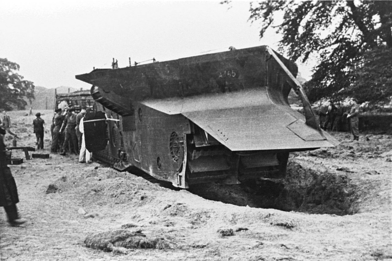
| Left: The White Rabbit on trials, rear view: 1939
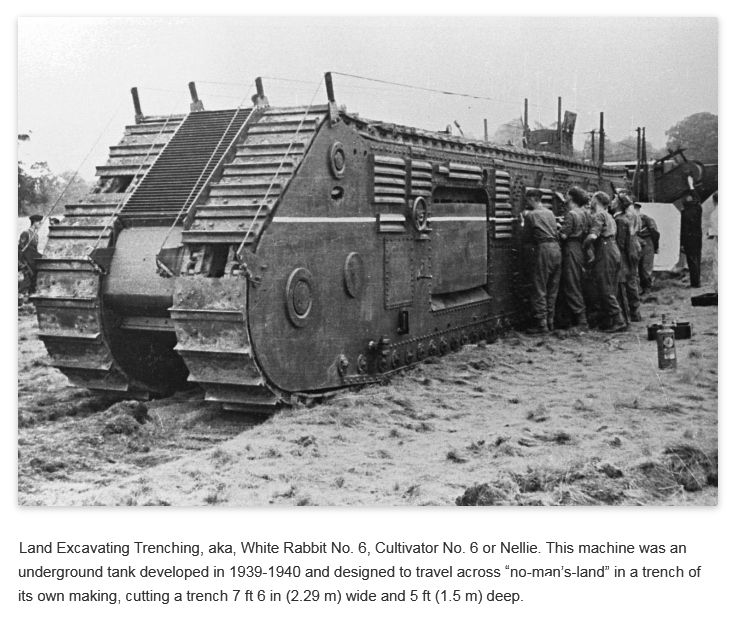
This extraordinary tank design was to supposed to advance across the battlefield in a trench it dug for itself as it proceeded. When it reached the enemy front line it was planned to stop and act as a ramp for tanks and infantry who had followed behind it along the trench. It was planned to be built in substantial numbers. The assumption was of course that WW2 would be a static affair of trenches like WW1. But it was anything but, and the project was reduced in urgency, and finally abandoned in May 1941. The idea was originally conceived by Winston Churchill during WW1.
The name White Rabbit was supposedly derived from the character in Alice In Wonderland who was always popping down holes. It was officially called Cultivator No.6, no doubt to obscure its real purpose. The prototype was nicknamed "Nellie".
The machines were built by Ruston-Bucyrus. They were originally inteded to be powered by a single 1000 HP Merlin aircraft engines, but since these were badly needed for aircraft, twin 600HP diesels made by Davey, Paxman and Co were used at the suggestion of that great man Sir Harry Ricardo. Diesel fuel would have been much safer than the petrol used by the Merlin.
It was an enormous machine planned to be built in substantial numbers. The overall weight was 130 tons and the length was 77 feet 6 inches. (23.62 m) It was built in two sections, to be split for transportation.
There is an excellent detailed Wikipedia page on the White Rabbit.
|
 |
| Left: The White Rabbit on trials, front view: 1939
This view shows the huge snowplow-like structure on the front of the White Rabbit. The machinery just below it presumably did the digging. Note the transverse tracks behind the snowplow; presumably they were for steering whilst digging forward. Only very limited steering was possible while digging.
|
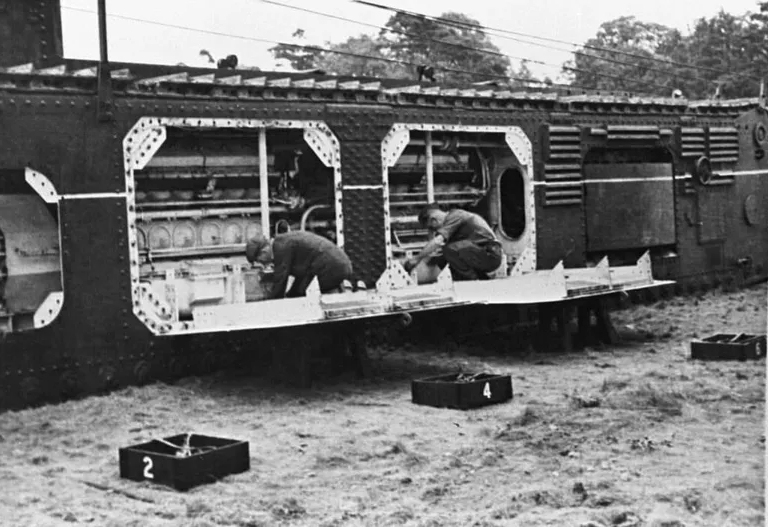 |
| Left: The White Rabbit on trials, side view: 1939
This shows the installation of the two Paxman diesel engines, in line ahead. The tracks can be seen running across the top. Note the oval door (reminiscent of a submarine) giving access to the engine department from the front.
|
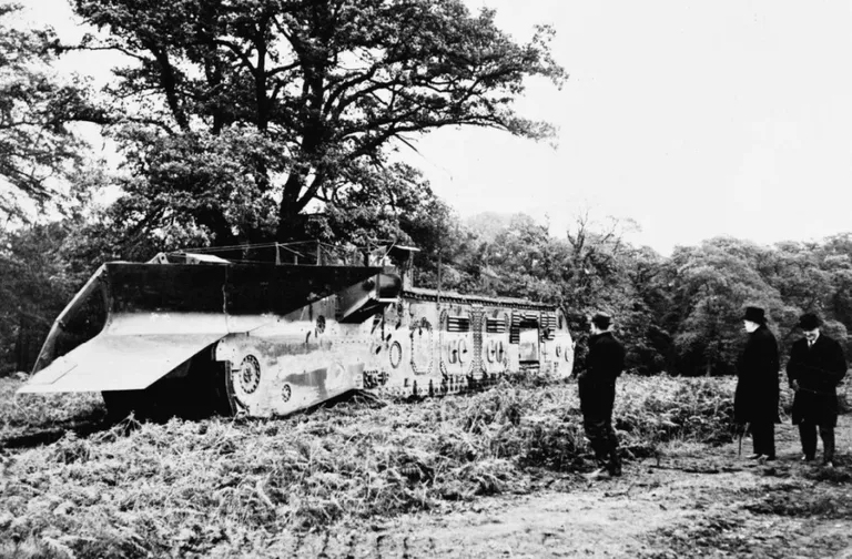 |
| Left: The White Rabbit on trials, side view: 1939
Another view: the tracks ran right round the profile of the tank, as on the WW1 rhombus-shape tanks.
It is possible the middle figure is Winston Churchill.
|
THE SCHOFIELD TANK: 1940
The Schofield tank was developed in New Zealand when the Pacific war was getting closer and there seemed little prospect of getting fighting vehicles from Britain. It had both four wheels and tracks.
 |
| Left: The New Zealand Schofield tank in wheel mode: 1940
The changeover from wheels to tracks, and vice versa, could be accomplished from within the hull. The wheels and the track sprockets shared common axles.
There is a Wikipedia page.
|
 |
| Left: The New Zealand Schofield tank in track mode: 1940
The wheels were carried on the side of the tank when not in use. They look very vulnerable to combat damage.
Initial trials were not very successful; an improved version was ready by 1942 but by then tanks were arriving from Britain and the US. In 1943 the project was abandoned. The prototype was put into storage and then scrapped post-war.
Other fighting vehicles that are wheeled and tracked can be found on the 'N-wheel car' page:
|
THE KUGELPANZER BALL TANK: WW2
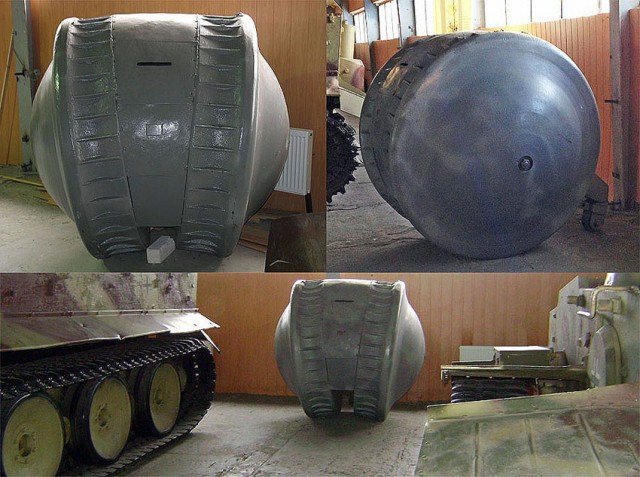 |
| Left: The German kugelpanzer tank: WW2
This montrosity was produced during WW2 by Krupp. Kugelpanzer literally means 'spherical tank'. Its purpose is still the subject of speculation; was it for reconnaissance, or wire-laying? It is usually called a tank, but with armour 5 mm thick at best, it would not do very well against real tanks.
There was a central cylindrical compartment with a single direct vision slit at head height, and below that is a welded-up hatch which could have been used by a machine-gun. There was an access hatch at the rear. The kugelpanzer was powered by a one-cylinder two-stroke engine, with which it could reach a slow 8 km/h. (5 mph) Steering and stabilisation was by a single wheel at the rear, which can just be seen in the picture at top right.
The only Kugelpanzer is in the Kubinka tank museum, having been captured by the Red Army; and apparently the Russians are very secretive about its materials of construction and the engine. It is very hard to see why- if it really had any military secrets it would never have been displayed in the first place.
There is more information at tanks-encyclopedia.com. The Kugelpanzer also has a Wikipedia page.
|
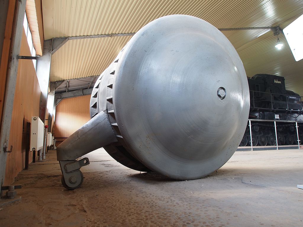 |
| Left: The German kugelpanzer tank: WW2
This gives a good view of the little wheel at the rear. It does not look well-suited to crossing difficult ground.
The idea of a spherical tank goes back to at least 1936; see Popular Mechanix.
The Kubinka Museum also has the only Maus super-heavy tank prototype, and also the only four-tracked tank prototype;
Object 279.
|
THE GERMAN WARGEL LW 3 TANK: 1942
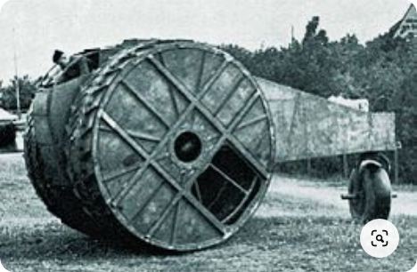 |
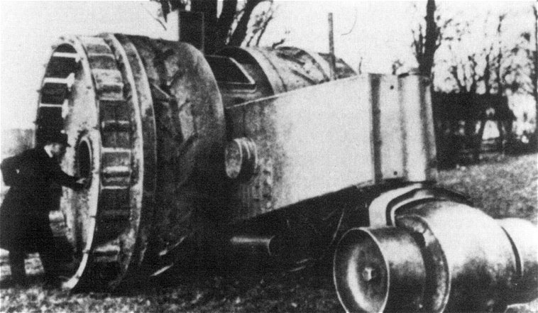
| Left: The German Wargel LW 3 tank: 1942
This picture greatly resembles the Treffaswagen above, but it is a later example of the big-wheel idea called the Wargel LW 3, built by Lauster GmbH in 1942.
The LW 3 was one of a series of Lauster designs running from LW 1 to LW 7. For example, the Lauster Wargel LW 5 had four big wheels and was constructed in 1943 to be a towing vehicle for a trench plough and as a heavy tank recovery vehicle. 'Wargel' is Swabian for a roller or drum.
There is more information here.
|
THE SWEDISH S-TANK: 1961
The opposite philosophy to that of the Tsar Tank was adopted by the Swedish Stridsvagn 103, better known as the S-Tank. This had some radical design features to give it a very low profile for a tank.
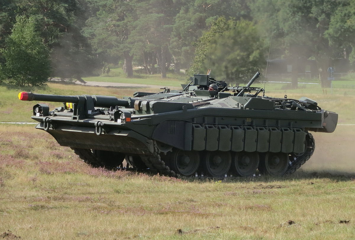 |
| Left: the Swedish Stridsvagn 103 fixed-gun tank
The S-tank has no turret, giving it a very low profile. The Bofors 105mm L/62 gun is fixed to the chassis; elevation and depression are carried out by adjusting the hydropneumatic suspension. The gun is trained left and right by the tank turning, which it can do smoothly and precisely, even if there are obstacles around the tracks. It can swivel on its own axis.
It could be argued that the S-tank is more of a self-propelled gun, but its envisaged combat role was that of a tank. The first two production prototypes were completed in 1961, and full production began in 1965. The last S-tank was retired in 1997, being replaced by the Stridsvagn 122 tank, which is based on the German Leopard tank and has a conventional turret.
|
There is a good Wikipedia page on the Stridsvagn 103.
There is a great deal of information at tanks-encyclopedia.com.


