Some people have felt that what the world needed was a mechanical horse; not a motor-car but a machine with mechanical legs. One motive was to get better off-road performance. A major difficulty if you want to construct a realistic mechnical horse is that horses have at least five ways of moving their legs; the walk, the trot, the canter, the gallop, and the pace. See Wikipedia on horse gait. There are also many kinds of ambling gaits which are faster than a walk but usually slower than a canter; ambling gives a smoother ride than either a trot or a pace.
Most, if not all, inventors seem to have decided that producing one gait was quite enough.

THE POTTER CART
This is not strictly a mechanical horse, but it does have four legs.
 |
| Left: The Potter Cart: 1663
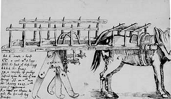
This four-legged cart was invented by Francis Potter. (1594 -1678)
Robert Hooke (1635 - 1703) was Secretary to The Royal Society from 1677 to 1682). Potter's invention was presented to The Society; Hooke made this drawing and added the comments at lower left. These read:
Let h. denote a horse
CC. a cart wth 4 leggs.
ffff. the feet of those leggs.
kkkk. the knees.
pp, a couple of pulleys fastened upon the ends of two springs: SS. on wch run
the chaines cccc, wch
move  j legs forward.
R, a rope or chaine to pull the for most leg straight
"Mr Hookes account of the Cart wth Leggs brought in by Mr. Aubery from Mr Potter was Read
and the same wth. some alterations was orderd to be sent to the author of this Inuention
together wth. the thanks of the society. Mr Hooke was also orderd to draw up a full
Description of this Cart together wth. the scheme thereof to the end that it may be
entred. wth the animaduersions upon it"
"Have drawn the Cart with Legs tho' I doubt its practicability." was Hooke's comment to The Royal Society. It is hard to disagree.
Source: Minutes of The Royal Society
|
It is unclear what the purpose of this invention was. Perhaps it was meant to out-perform wheeled carts on rough ground; it seems highly unlikely that it would have been attended with any success. There is nothing to move the legs apart from the forward pull of the horse.

BRUNTON'S TRAVELLER
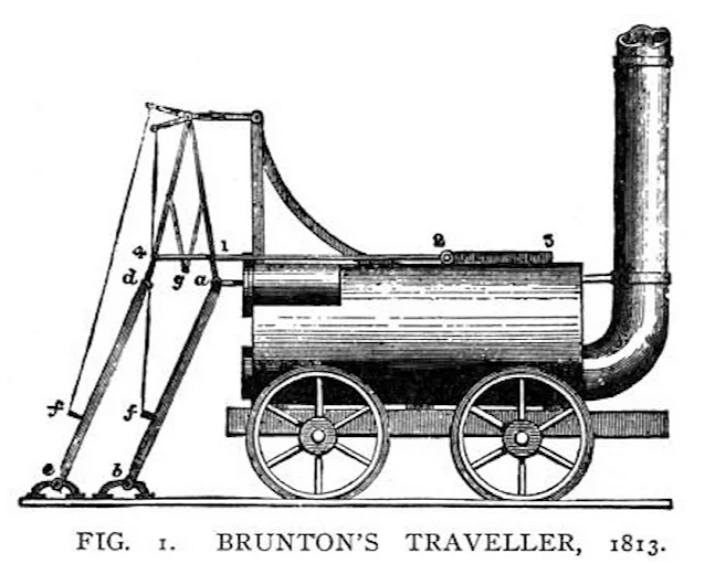 |
| Left: Brunton's Traveller: 1813
In the early days of steam locomotion there was much doubt about the ability of steel wheels to gain traction on smooth steel rails. Brunton's Traveller did not drive its wheels and instead had two bizarre legs at the rear to push it forward; each leg was driven by a steam cylinder. Two chains marked f and f lifted the legs on the forward movement. The diagram seems to have some parts missing, notably the piston rod driving the leftmost leg. On top of the boiler, between 2 and 5, there was a pinion engaging a rack on either side, to keep the legs moving in opposite phase. Nothing is known about the valve gear.
Unlikely as it may seem, the locomotive seems to have operated successfully between 1813 and 1815. Another larger walking locomotive was built, but came to a bad end:
"The invention excited much attention. It had the merit of acting as the designer intended it should, and one day that it was on trial, rushing along at a speed of three miles an hour, accompanied by a host of admirers, the boiler exploded, throwing hot water, pieces of iron, and disaster among the crowd. That ended the career of the Mechanical Traveller."
Apparently thirteen people were killed, and others injured. This is often considered the first railway accident. (NB This Philadelphia is in County Durham, England) It occurred 15 years before William Huskisson's fatal accident.
|
Source: Curiosities of Locomotive Design. From Development of the Locomotive Engine, by Angus Sinclair. Railway and Locomotive Engineering: September-December 1907
|
This locomotive has a good Wikipedia page.
You can see a fine model of the Traveller, built by Adrian S in 2017, on YouTube. Weights have been added to the leg-lifting mechanism.i
Here is a good video of the model walking on a turntable. This shows the rack and pinion mechanism.

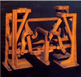 |
| Left: Chebyshev's Walking Machine: 1850
One of the first steps (ho-ho) toward a true walking mechanism was made by Pafnuty L Chebyshev, who is most famous as a mathematician.
Here is one of the better animations.
|
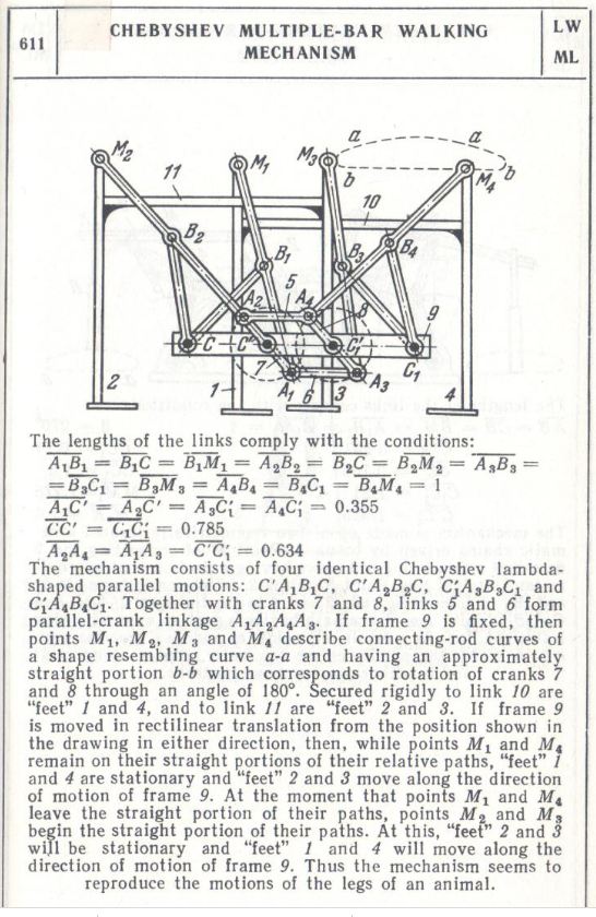 |
| Left: Chebyshev's Walking Machine: 1850
Here are all the technical details of the Chebychev walker. It is operated by turning the double-cranks C' and C''. Best to have a look at the animation before trying to work it out.
|

RYGG'S PEDAL-POWERED HORSE
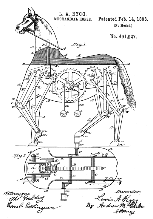 |
| Left: Pedal-powered mechanical horse patent: 1893
Unlike some of the other mechanical horses, it's pretty clear how this one works. Each leg is in two parts, the upper part Y pivoting on the chassis at its top end. The lower part of the leg S is moved by crank d and connecting rod R. The front and back cranks were driven by the central wheel to which the pedals were connected. This was geared-up by about two to one, and I would have thought it would require a great deal of force on the pedals to make this machine move.
The front gear F is of a barrel shape so it remains engaged when the front legs are turned for steering.
Source: Popular Science, April 1933
|

UNKNOWN MECHANICAL HORSE
 |
| Left: Unknown mechanical horse: 189?
All we have here is the photograph, with no info at all. A Google image search yielded nothing.
It looks as though the horse is moved by the front legs, for no drive to the rear wheels is visible. It appears the legs are steered by the handlebar affair just behind the horse's neck.
The power source is not definitely known, but to me the machinery at the rear is more suggestive of storage batteries and an electric motor, rather than a petrol engine. There is no sign of a petrol tank or an exhaust pipe.
The purpose of the sunshade above the horse's eyes is unknown.
|

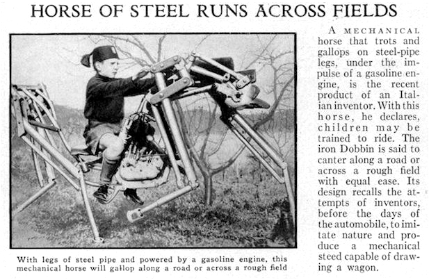 |
| Left: The Iron Dobbin Mechanical Horse in Italy: 1933
This looks like a rather dangerous piece of machinery, powered by a petrol engine that looks as though it came from a motorcycle. It seems highly unlikely that it would be a good way to teach children how to ride a real horse, but that was its purpose. It was supposedly capable to traversing rough terrain. The authorities considered putting the vehicle into limited production to train the children of the Gioventý Italiana Littorio (Italian Fascist Youth Movement) to ride, but the Italian military deemed it impractical. The 'Iron Dobbin' was also rejected as a replacement for mountain troop donkeys.
Apparently the German military drew up plans for their own version to be named the Panzerpferd (Armoured Horse) for their Gebirgsjaeger mountain troops, who equally rejected the idea. No further info on this project has been found.
Teaching potential soldiers to ride a horse in 1933 may sound backward but many armies (including the German Army) were still making extensive use of horses at this time.
The Iron Dobbin has a Wikipedia page, but it has no more information.
Source: Popular Science, April 1933
|

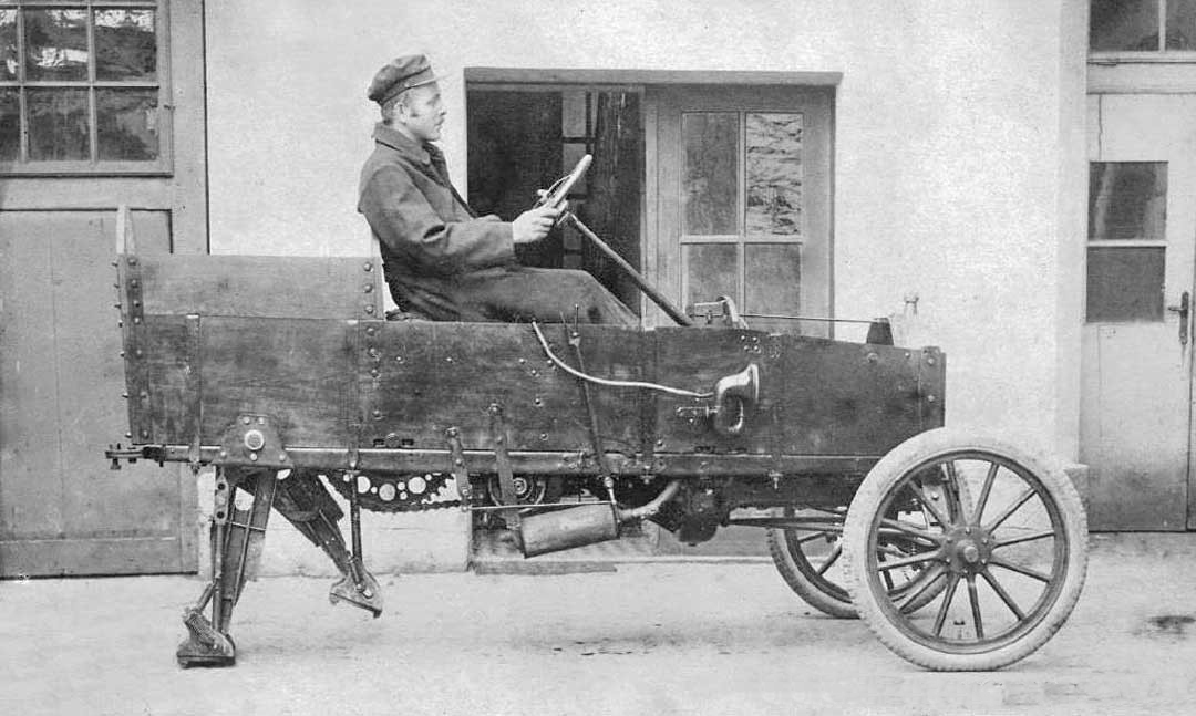 |
| Left: Mechanical horse : 19??
I have heard it said that this is a conversion of a Model-T Ford. If so it appears nothing is left of the original car but the engine. Nothing is known about it, and a reverse image search yielded nothing.
Presumably that great big chain-wheel drove some sort of system of cranks to move the legs.
Source: unknown
|

THE PEDAL-POWERED WALKER
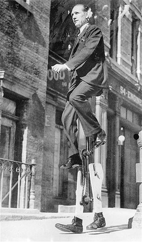 |
| Left: Pedal-powered walker: 193?
Obviously this not a mechanical horse, but a mechanical man; until further notice it goes here, however. This is Mister Walter Nilsson in the 1930's. The mechanical legs appear to be moved by a simple pair of cranks. Mr Nilsson has Previous; he is better known for building a
monowheel. Here he is 'walking' to work in Los Angeles.
What he was aiming for here clearly isn't a better way of getting from A to B, self-advertisment was the goal. He also built a bicycle with square wheels, and rode unicycles in "Hellz-a-Poppin" a stage musical that ran on Broadway from 1938 to 1941. He seems to have been quite well-known; there is an article on him here.
Source: unknown
|

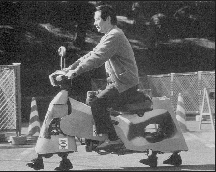
THE FOOT-SCOOTER 'HORSE'
 |
| Left: Foot-scooter horse : 19??
This picture was found on the Web. Nothing is known, though it is obvious that steering is catered for by swivelling the front as in normal motor-scooters. If anyone can shed any light I would be most grateful.
A reverse image search gave nothing.
While the booted feet prevent it from being a perfect emulation of a horse, it definitely has four feet. Mind you, horses do wear boots sometimes.
Source: unknown
|

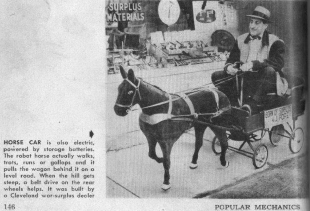 |
| Left: Bogart horse : 1953
George Bogart of Cleveland Ohio built this model horse in 1953, for a bet.
It was powered by two six-volt car batteries. The pulley wheel in the middle of the rear axle could be connected to the electric motor if the hooves did not give enough traction. I think there may also be a bit of cheating going on as regards the steering.
The article text says the horse could walk, trot, run, or gallop; this suggests four different selectable gaits that would be very complicated to reproduce mechanically.
Source: Popular Mechanics Jan 1954
|
 |
| Left: Bogart horse patent: 1958
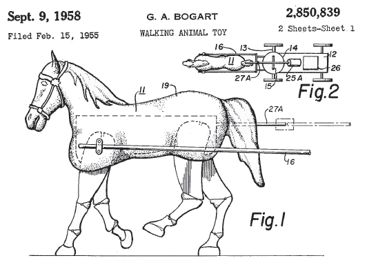
George Bogart's interest in mechanical horses was not a mere whim. In 1958, five years later, he took out this patent for a walking toy horse.
Figure 2 shows an electric motor 25A mounted in the cart being pulled. Power reaches Dobbin via a rather unfortunately-placed horizontal shaft.
Source: US patent 2,850,839 of 1958
|
 |
| Left: Bogart horse : 1953
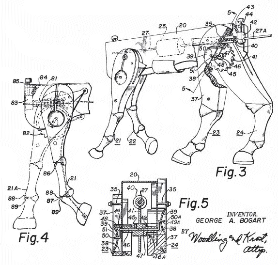
Each leg had two joints and appears to have been moved by a wire or chain running to the bottom of the leg; this was pulled on by cranks. At front and back was a gearwheel driven by a worm gear on the horizontal shaft.
Here the electric motor 25 is mounted inside the body of the horse.
Source: US patent 2,850,839 of 1958
|

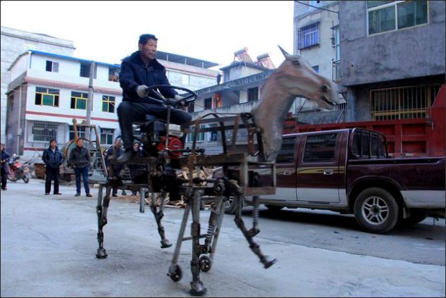 |
| Left: Chinese Mechanical horse: 2014
This mechanical horse weighs 250 kg and was built by Mr Su Daocheng.
You will note just a little bit of cheating in the shape of a two-wheeled trolley just behind the front legs.
Source: Unknown
|

A MODERN WALKING MACHINE
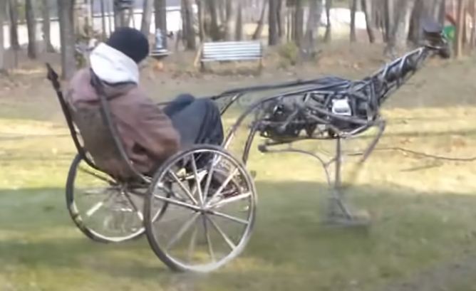 |
| Left: A Modern Walking Machine: 2018
This rather elegant walking machine has only two legs, so it could be considered as a mechanical emu or ostrich. Judging by the soundtrack, it is powered by a small IC engine. The walking mechanism is delightfully simple, the lower leg being a bell crank moved back and forth by a crank at the rear. It is reins-guided, the steering being very effective. The head looks from side to side but this appears to be automatic and unconnected with the steering. A magnificent job!
You can see the video on YouTube. As is so often the case with YouTube, no additional information is given.
|

A WALKING MACHINE
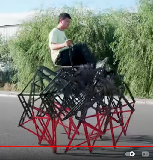 |
| Left: A Modern Walking Machine: 2022
A still picture gives very little impression of this most impressive machine. It has six legs on each side, propelled by pedal-power. There appears to be a differential built into the driven chainwheel, which allows the machine to turn when it is braked on one side; see it at 7:10 in the video.
I thought 'Strandbeest' was Dutch for 'walking machine' but it actually means 'beach beast', which seems to be a reference to the machine just below..
You can see the video on YouTube.
|

ANOTHER WALKING MACHINE
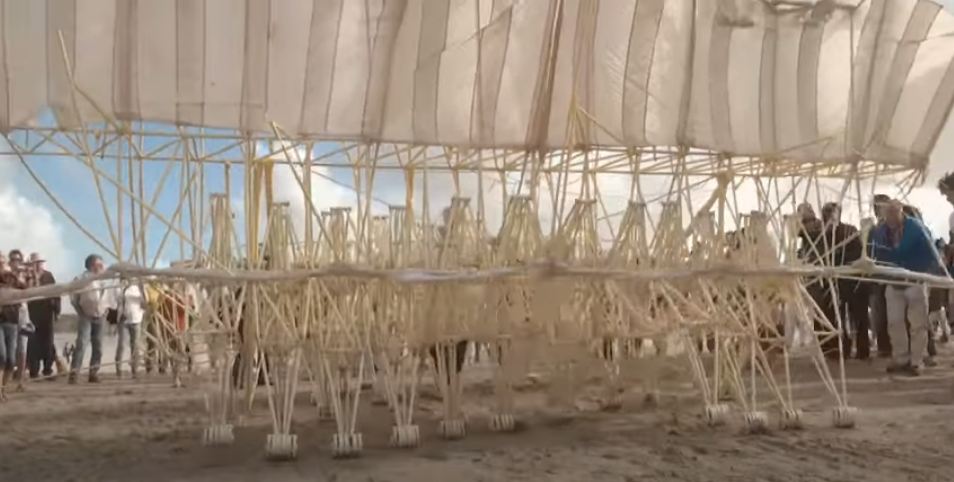 |
| Left: A Modern Walking Machine: 2022
This is even more extraordinary. This machine has a LOT of feet, in front and rear ranks. It's very hard to count them on the video, but I make it something like 10 feet at the front and 15 to the rear. It is pushed along by three sets of sails, (which it can wave in the wind) but can also be pushed by hand. It is made of PVC tubing, and was built by Theo Jansen, who has a solid reputation for building kinetic art. He has an amazing website at strandbeest.com, which among many other wonders shows a 36-legged sail-powered walking machine called the Volantum. You will also learn how Jansen's strandbeests can fly.
The location is the beach at Scheveningen, Holland.
You can see the video on YouTube.
There is another video on YouTube here, and instructions on making a walking machine out of lolly-sticks here.
|

BLUE MECHANICAL HORSE
 |
| Left: A Blue Mechanical Horse: date??
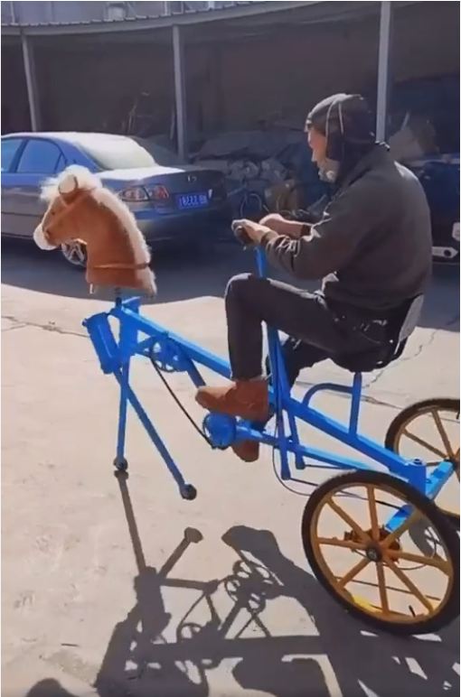
Not sure what else to call it. A video showing this very functional horse-machine is all over the Internet, but regrettably no other information has been found.
Steering is by two levers that swivel the rear wheels.
You can see the video on Instagram or Pinterest.
|

FRANK STUART'S MECHANICAL ELEPHANTS
 |
| Left: Frank Stuart's Mechanical Elephants: 1965
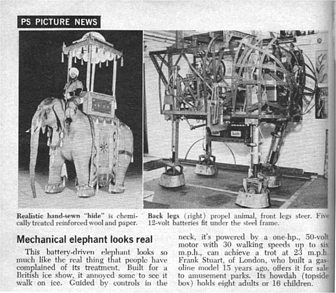
This may not actually be a horse (but then neither is Theo Jansen's walking machine) but it is identifiably a mechanical elephant, and a very good one. Several were built; this version has a chassis made of Dexion, perforated metal strips like giant Meccano.
The elephant was propelled by its back legs and steered by its front legs. It was powered by a 1 HP electric motor and five 12V lead-acid batteries; (Made by Exide in this case) slung under the main chassis to keep the centre of gravity low. The hand-sewn "hide" was chemically treated reinforced wool and paper; the elephant was so realistic that there were complaints to the RSPCA when the machine was exhibited walking on ice.
There is a great deal more info in the Cybernetic Zoo.
Source: Popular Science for May 1965
|
 |
| Left: Frank Stuart's Mechanical Elephants: 1965
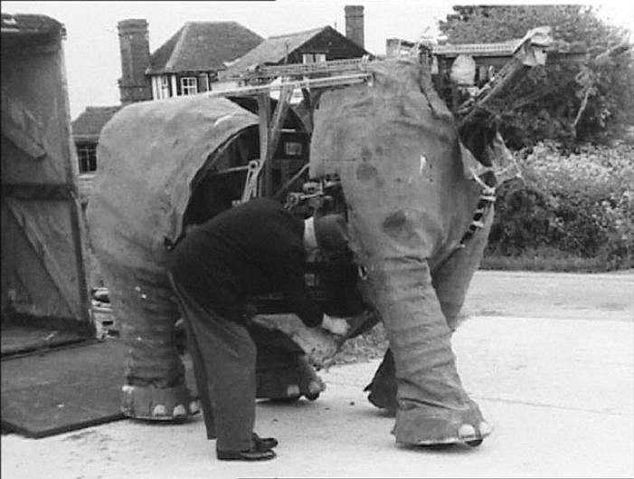
One of the Electrophants gets some attention.
There is another page on the earlier (1950) Stuart mechanical elephants in the Cybernetic Zoo.
|
In the course of preparing this Gallery, the Museum Staff have become aware that the Internet is awash with walking machines, if that's the correct way to put it. This Gallery makes no attempt at completism- the machines here are but a sample.


