A steam-motor locomotive typically has a relatively small multi-cylinder steam engine which is geared down to the driving wheels. Doubling the speed of a given engine doubles its power output if everything else remains constant; alternatively, you can have the same power output from a smaller and lighter engine. Another benefit is smoother driving torque, because of the greater number of power strokes for each revolution of the driving wheels.
The locomotives on this page are confined to those whose most unusual feature was the steam-motor. Other designs had more radical features than their steam-motors, such as high-pressure boilers, and are placed in that gallery of the Museum. Examples are:
The French 232.P.1 of 1939 (High-pressure boiler, motors for each driving axle)
The Swiss Eb3/5 (High-pressure boiler, uniflow motor)
The 221TQ: France
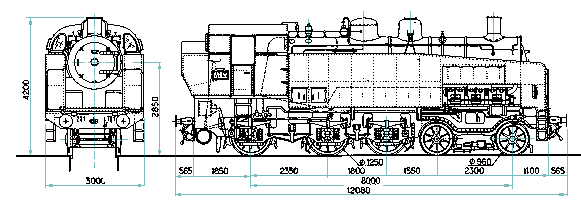
This curious machine resembled a type 230 tank engine, without coupling rods. The side water tanks are cut away above the leading bissel truck to allow room for the cylinders of a V12 high-speed steam engine, which drove the first two axles through reduction gearing; the rearmost wheel was not driven. The boiler and superheater were conventional. This machine "did not give satisfaction" on the test bench at Vitry and it was planned to rebuild it.
 |
| Left: The 221TQ at Vitry
This appears to be the only photo in existence.
The simple (non-compound) V12 motor was described as "Type Dabeg" and appears to have relied entirely on altering the cut-off for control. The valves were desmodromic, ie with positive opening and closing rather than relying on springs for closing, as with modern IC engines.
The cylinders drove a longitudinal crankshaft which in some way so far obscure drove the wheels through hollow driveshafts and flexible couplings.
|
 |
| Left: The 221TQ
Some hard facts:
Weight 79 tonnes
Adhesion weight 40 tonnes
Tractive effort 12000 kgf
Cylinder diam 200 mm
Cylinder stroke 280 mm
Boiler pressure 20 Bar (280 psi)
Injectors2 Thermix CV308
BlastpipeKylchap
| | | | | | | | | | | | | | | |
|
I am no locomotive designer, but the relatively low adhesion weight raises an eyebrow; it would
been a larger proportion if the rearmost wheels had been driven as well. Possibly the firebox and ashpan prevented a driveshaft extending further to the rear.
The V19.1001: Germany
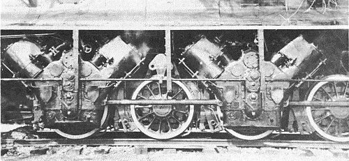
The remarkable V19.1001 was a V8 locomotive, having four V2 engines, one for each driving axle. The wheel arrangement was 2-8-2. (Mikado)
The V19.1001 was originated by Fredrick Witte, head of testing and development for Deutche Reichsbahn. The concept was first discussed at DR in 1933, and plans drawn up in 1935. The detail design was done by Richard Roosen of Henschel & Son. It was delivered to the DR in July 1941.
 |
| Left: The 19-1001 with its streamline casing.
|
 |
| Left: Two of the V2 engines.
The engines for two of the axles are on the other side.
|
 |
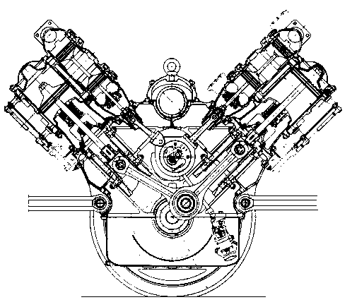
| Left: Side section of one of the V2 engines.
Sectioned on the line A-B in the drawing below.
Note the piston valves driven from what appears to be a central camshaft. John Dabrowski has pointed out to me that it could be an eccentric with a master-slave connecting rod assembly as used on radial aircraft engines.
|
 |
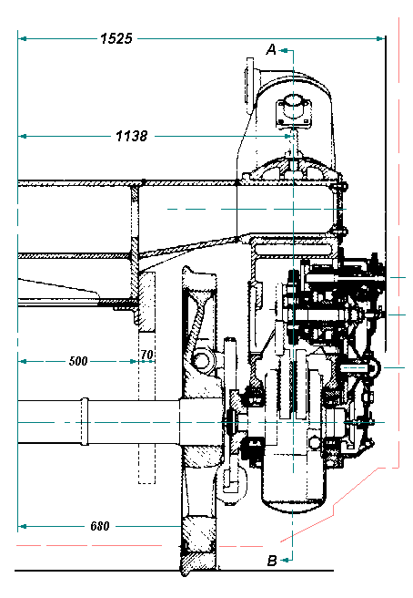
| Left: Longitudinal section of one of the V2 engines.
The crankshaft is not directly connected to the driving axle, but drives it via the flexible coupling
The central camshaft is driven by a gear-train with an intermediate idler.
Dimensions in millimetres.
|
In October 1944 the V19.1001 was seriously damaged during an air raid on Hamburg. It was moved to RAW Braunschweig and stayed there until the end of the war. In August 1945 the locomotive was brought back to Henschel, repaired, and after one test run between Kassel and Wabern, was shipped to the USA in October 1945. It was sent to Fort Monroe in Virginia for testing and inspection, and in 1950 was moved to Fort Eustis and scrapped there in 1952.


