Updated: 19 Apr 2005


Updated: 19 Apr 2005
|
In December 1905 the first boiler was ordered from the Creusot works. Trials were concluded in 1907. The bottom steam drums were of cast steel, protected from the direct heat of the fire by fire-bricks, which gave endless trouble, being rapidly eroded. There were also intractable leaks where the tubes joined the rear tube-plate, caused by a lack of rigidity. However, The Engineer said: "But the most important leakage arose from the unequal temperatures between the top and bottom of the boiler. To ensure that the water passing into the water tubes should be as free from deposit as possible, the makers had placed high up on the boiler barrel the pipes which connected the boiler with the collectors. this caused violent differences of temperature, owing to imperfect circulation, until the boiler was producing steam for the cylinders." I must admit I find this explanation somewhat opaque. Does it mean that the temperature differentials caused expansion that opened up joints in the boiler?
Despite this, the first water tube boiler was said to have been "a successful and economical steam generator".
A second, modified boiler was ordered from the Creusot works in 1908. This version built on the lessons of the first; it had no firebricks and a vertical array of water-tubes protected the rear tube plate of the boiler from direct flame. (See section on line LM below) The firebox was joined much more rigidly to the boiler barrel. The heating surface was about 1000 sq ft, with a great area of 37 sq ft; figures that were thought to be unprecedented. At the time of the Engineer article, the engine had run over 20,000 miles in normal service, and it was said: "... so far no wear can be observed on any of the water tubes, while there is no perceptible amount of sediment deposited in any part of the boiler..."
However... there were no more water tube boilers on the Nord. I have not so far found any more information on the trials. Can anyone help? Very probably the hopes of reduced maintenance costs were not realised.
All the images below are of the second version of the boiler.
|
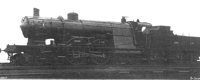
Above: The Nord Water-Tube Boiler Locomotive.
|
|
Above: Exterior View of The Nord Water-Tube Boiler Locomotive.
|
|
Above: The Water-Tube Boiler.
|
| Left: Section of The Firebox.
|
| |
Above: Sections of The Firebox.
|
