Updated: 8 Mar 2015
Photo of Heilmann No 1


Updated: 8 Mar 2015 |
The Heilman locomotives were the first steam-electric designs, using a reciprocating steam engines to drive DC generators, which in turn powered electric motors mounted directly on the axles.
![]()
THE FIRST HEILMANN LOCOMOTIVE: Le Fusée Electrique. (The Electric Rocket)
Jean-Jacques Heilmann, proprietor of the Société Industrielle de Moteurs Électriques et ŕ Vapeur in Le Havre, took out his patent for a steam-electric locomotive on July 18, 1890, and the first prototype was built in 1892-93. Heilmann and his coworker Drouin began with static tests to determine whether DC or the recently introduced 3-phase AC would be most suitable for their purposes. It was quickly found that DC would be best, as it allowed the steam-engine and generator to work at a constant efficient speed, while the traction motor speed could be quite different.
Heilmann was from Alsace, which no doubt accounts for his rather Germanic-sounding name. A Joshua Heilmann was a noted textile engineer in Mulhouse (often regarded as the industrial capital of Alsace) working on woolcombing machines and mechanical embroidery equipment, around 1845. Very possibly he was the father of J J Heilmann.
The chassis of Le Fusee was 16.3 m long overall, mounted on two 4-axle bogies. Each axle was driven by a 60 hp electric motor. The total weight (and I haven't yet worked out if this was wet or dry) was 110 tons. Electricity was generated by a 400 kW generator, driven by a horizontally-opposed two-cylinder steam engine. The field current for the generator was supplied by a small vertical steam engine driving a dynamo.
 | The Fusée, the first Heilmann locomotive, on trials in 1894
|
 | The Fusée, the first Heilmann locomotive, fitted with a rather unattractive wooden body
|
 | The first Heilmann, with the wooden body removed.
|
 | The first Heilmann
|
 | Another picture of the first Heilmann with the body removed
|
 | Some details of the first Heilmann.
|
After completion the locomotive Fusée, in Autumn 1893, made a test run on the Le Havre- Beuzville line. The locomotive gave good results, especially as regards its high starting tractive effort. On 9 May 1894 it set off on the Compagnie des Chemins de Fer de l'Ouest (West) network from Paris St-Lazare station and hauled to Nantes and back a special train carrying 250 guests. This excursion went smoothly with an average speed of 75 km/hr, while for a short time a maximum speed of 107 km/hr was achieved. The machine could haul a passenger train of 80 tons at 100 km/hr.
One problem that appeared was difficulty of communication between the driver and the fireman, who were separated by the engine and generator. Testing continued, about 2000 km in total being covered, and this gave the Ouest railway confidence to order two more Heilmann locomotives of greater power: see below.
 | The engine of the first Heilmann: sectional endview
|
 | The engine of the first Heilmann: exterior endview.
|
 | The engine of the first Heilmann: plan view.
|
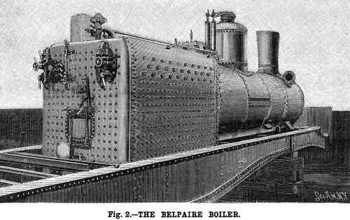
 | The Lentz boiler of the first Heilmann
|
There is a combustion chamber between the grate and the boiler tubes. No superheater tubes are visible.
 | Another Lentz boiler
|
This boiler type was originated by Hugo Lentz (1859–1944) an Austrian mechanical engineer. He is better known for the Lentz oscillating-cam poppet valves fitted to a good many locomotives. A similiar type of boiler was used on the Lancashire & Yorkshire Railway but does not appear to have been a great success.
![]()
A MODEL OF THE FIRST HEILMANN
So far I have found no photographs of the first Heilmann, though some must surely exist somewhere. What I did find, quite unexpectedly, was a fifth-scale model in CNAM, the Conservatoire National des Arts et Metiers in Paris. (This is a wonderful museum, full of all sorts of gems such as Cugnot's steam carriage- the original, not a replica. You can also get a lunch that fully upholds the reputation of French cuisine)
This model was built by Jean Jacques Heilmann himself, in 1903. This is after the trials of the second version, and apparently by this time it was clear that the Heilmann concept was not going to be adopted. This eems a little strange; you would have thought the model would have been built before the first full-size locomotive was constructed. But, that's what it says on the label in the CNAM, so there it is.
These photographs were taken in available light, with a handheld camera and through the glass case, so I'm afraid the image quality is not stunning.
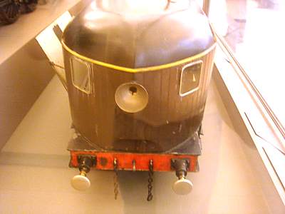 | Model of the first Heilmann: the front.
|
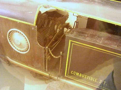 | Model of the first Heilmann: the engine.
|
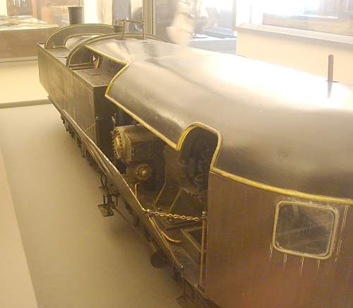 | Model of the first Heilmann: the side.
|
![]()
THE BIG HEILMANNS.
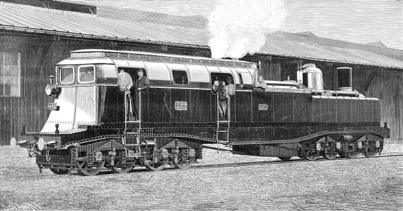
Two new locomotives were built, numbered 8001 and 8002.
The improved design used a conventional Belpaire boiler without superheater and a much more powerful Willans high-speed vertical steam engine to drive the DC generators. 1000 kW of mechanical power was produced at 400 rpm, and each six-pole generator gave 450V at 910A, or 410 kW each. The generators could sustain a 100% overload for 15 minutes, and a 50% overload for 30 minutes. The exciter dynamo was driven by a small-cylinder engine developing 18 kW at 550 rpm; the exciting voltage was 110V and 140A was available. Only 100A was required for excitation of the main generators, the surplus being used for lighting. The electrical equipment was once again supplied by Brown Boveri & Co.
The first of the two machines made its initial test run of 115 km on 12 November 1897. The load consisted of 12 personnel and a test van, giving a total weight of 150 tonnes, and the maximum speed was restricted to 30 km/h. These tests were completed without difficulties. On later test runs the total weight was increased to 250 tonnes and speeds increased to 100km/h. The maximum speed attained was 120 km/h. The two big Heilmann locomotives clearly showed their advantages over the classical steam locomotive. The total weight was usable for the adhesion and the design gave good acceleration and traction power as well as outstandingly quiet running over the whole speed range.
The design aroused the interest of other railway networks- for a while at least. The Russian Southern railway and the Ohio River, Madison & Central railway of the USA (?) both tentatively planned the building of such locomotives. There was also interest in Germany. Nothing however came of this international attention.
A few hard facts:
Service weight124 tonnes
Adhesion weight124 tonnes
Wheel diameter1160 mm
Grate area3.34 m2
Evaporation surface185.5 m2
Steam pressure204 psi
Steam temperature194 degC |
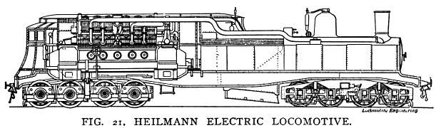
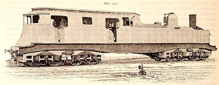
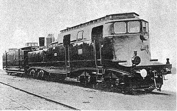 | Left: The Heilmann Steam-Electric locomotive. It was basically a cabforward design, but it could run in either direction. |
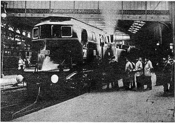 | Left: The Heilmann locomotive 8001 at Gare Saint-Lazare in Paris, about to set off on a test run. |
 "> "> | Left: The Heilmann Steam-Electric locomotive
|
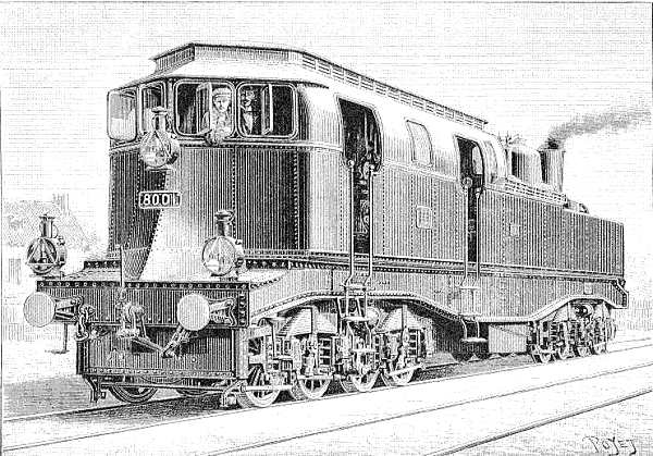 | Left: The Heilmann as pictured in the French scientific journal Nature.
|
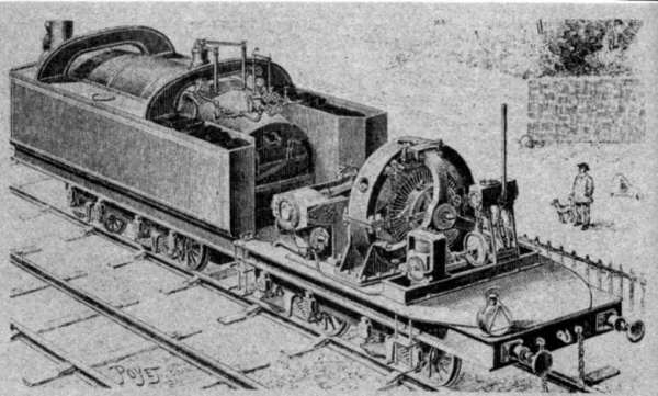
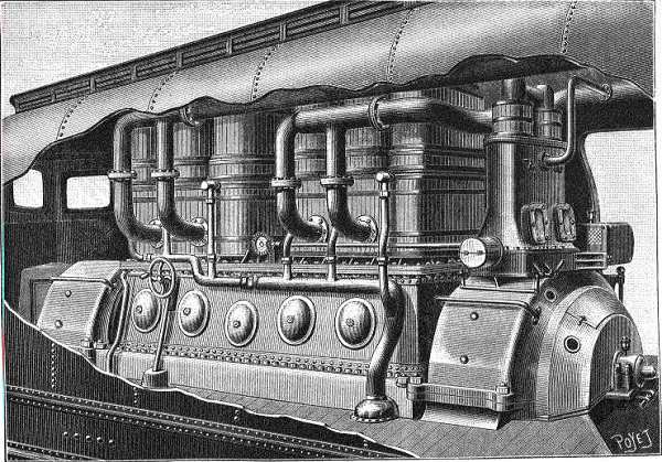 | Left: Cutaway drawing of the Heilmann, showing the Willans engine.
|
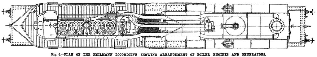
Above: Plan view of The Heilmann. The big 6-crank Willans engine is to the left, the boiler to the far right.
The exciter engine is immediately to the right of the main engine. The long middle pipe took the steam from the regulator to the engine. The long pipes at top and bottom carried the engine exhaust back to the blastpipe in the smokebox.
Above: Another side view, probably taken from the same original drawings.
This is a simplified circuit as the big Heilmanns actually had two main generators.
DC was used for ease of motor control.
An extract from a Scientific American article on the big Heilmann engines:
"It is now some three years since Mr. J. J. Heilmann, of Paris, designed and placed in operation his first standard gauge electric locomotive, which was known as La Fusee Electrique and was tested upon the lines of the Compagnie des Chemins de Fer de l'Ouest,of France. The Fusee was of 600 horse power and 120 tons weight and it was designed for hauling the ordinary class of passenger trains. The novelty of this locomotive consisted in the fact that it did not take its current from a feeder connecting with a distant power station, but carried its power station with it— the boiler, engine, generators, and motors being all combined in one machine upon one set of wheels and comprising an absolutely self-contained electric locomotive.
"There is a further economy, it is contended, in the use of a many-cylindered high speed engine, and although considered as an electric motor, there is a greater weight of machinery to be carried than in a motor driven from a central station, this is offset by the absence of any loss by transmission over a line of greater or less length.
"It will be argued that the ordinary electric motor is also balanced, and that the extra load of boiler, engines and generator are a distinct handicap to this engine. To this it must be answered that in a locomotive of 1,350 horse power, which it is claimed the new machines will develop, the load of boiler, engines, etc., is almost necessary to give the requisite adhesion when the locomotive is working up to full power, as in starting or on a steep grade.It is evident that in proportion as the weight of the steam boiler, engines and generators become necessary for adhesion, the advantages of their installation in a separate power house disappear.
"The above facts show that the design is per se not so altogether indefensible as many of its critics have roundly declared; and the aims of its designers appear yet more reasonable when they state that in building the Heilmann locomotive an effort is being made to make it possible to equip the trunk railroads electrically, without making any radical changes in the road itself. With this fact in view, it must be admitted that whether the arguments above given are sound or not, this machine will enable the railroad companies to experiment with electric traction on a limited scale without undertaking the great expense which will be entailed in the use of the central station system.
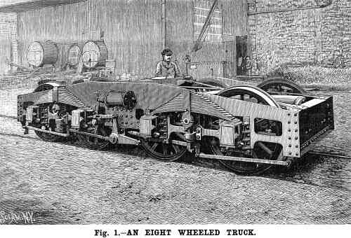
"The machine is built upon a pair of deep plate girders and carried by a couple of eight-wheel trucks, one under each end. The total length of the engine over all is 61 feet and the rigid wheel base measures 37 feet 3 inches. The front of the engine is not, as one would suppose from looking at the engraving, the end occupied by the boiler, the latter being placed over the rear trucks, the forward half of the platform carrying the engines, generators, exciters, etc. Water is carried in two tanks, one on each side of the boiler, and the coal bunkers are situated just ahead of the tanks and on each side of the fire box. The engines, generators, etc., are completely housed in by a large plate-steel cab or casing which is given a sharp, plow-like format its forward end with a view to reducing the air resistance.
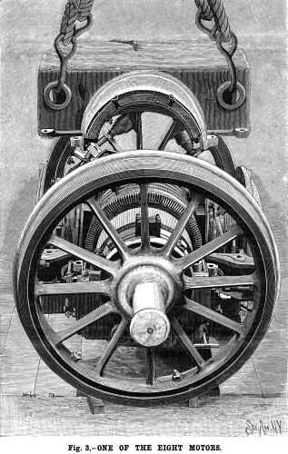
"There are two continuous current generators directly connected to the main shaft, one at each end of the engine. The generators, which were built by Messrs. Brown, Boveri & Company, are continuous machines coupled in parallel, and each has a capacity of about 1,000 amperes at 450 volts. They are excited by a small four-pole self-exciting dynamo which is driven by a simple Willans engine of about 28 horse power. The current is led to eight motors, one for each axle of the trucks. The motors have four poles, with two field cores placed horizontally.
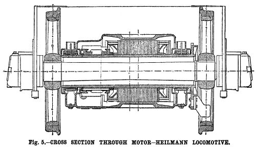
"The field winding is an insulated copper strip and the armature is a toothed drum wound in series and mounted on a hollow steel shaft which carries at one end a disk. This disk transfers the motion to the axle by means of three powerful links which are carried upon three corresponding pairs of springs secured between the arms of one wheel. The arrangement is shown in Figs. 3 and 5 in the accompanying illustrations. The axle passes with sufficient clearance through the hollow shaft,and the springs have sufficient flexibility, even under the full power of the motor, to allow free movement of the hollow shaft. The motors are all connected in parallel and each motor is fed by a special circuit from the switchboard and has its own switch and automatic cutout. For low speed and under heavy loads the motors may be grouped in a series of four by means of a controller. There is an eight-way switch for reversing the current in the armatures of the motors and for instantaneously changing their direction. The speed may be varied by means of a rheostat placed in the exciting circuit of the generators.
The big Heilmanns were in many ways a success, but no more were built. It was complex and expensive, and heavy for the power it generated. One serious disadvantage was that it needed a crew of three; a driver, a fireman, and a "pilote électricien" to manage the electrical system; this last crewmember is rather puzzling as the electrics do not look complicated. Conventional locomotives only required two men.
The subsequent activities of Mr J J Heilmann are currently unknown, except that they included model engineering. (see above)
MORE PICTURES OF THE BIG HEILMANNS
The dates, and in most cases the locations, of the photographs are not currently known.
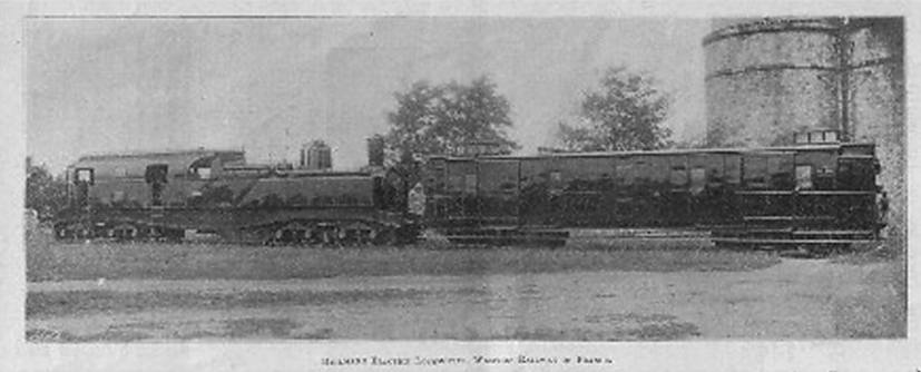
A beautiful picture. No 8001 stands, at first sight in a Paris street, coupled to what appears to be a brake van, judging by the cupolas on top of it. Determining the general location of this photograph was one of the less challenging tasks faced by the staff of the Museum.
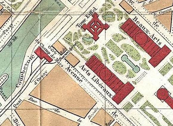
As I said a little while ago, given some old maps of Paris, it ought to be possible to work out the exact location. John Bevan tells me: "The photo of Heilmann 8001 with the Eiffel Tower in the background seems to have been taken at or near the Gare du Champs de Mars. The station was located near where the Australian Embassy is now located." This seems very likely as the line to the Gare du Champs de Mars was the only railway running near the Eiffel tower (erected 1889) at the time; it was also part of the Ouest railway network on which the Heilmanns were trialled.
The line was originally built to serve the 1867 Exposition Universelle. The station was demolished afterwards, but rebuilt for the 1878 Exposition Universelle. This was in turn demolished in 1894 and rebuilt for the 1900 Exposition Universelle, with the line extended to the Invalides terminus and and moved to the side of the Seine. This is quite a bizarre story in itself. In 1988 Champs de Mars became a stop on the RER C, a new suburban railway line serving the Eiffel Tower. The station is now located below the Quai Branly.
The Seine would have been to the left of this photograph. No station buildings are visible in the left background- just trees.
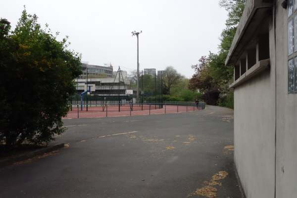
As well as a passenger station, in 1900 the Ouest also built a goods station between the Avenue de Suffren and the Boulevard de Grenelle, and that must be the likeliest location for the photograph; there appears to be a loading gauge in the left background. Both of these roads still exist; the Avenue de Suffren is on the south-west side of the Champ du Mars, and the Boulevard de Grenelle to the south-west of that. Until 1937, the goods station was a busy coal terminal. The site then became an EMU shed, closing in 1971. Unsurprisingly, there is no sign of a goods yard today. Its position is now occupied by the Stadium Emile Anthoine.
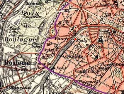
The station is highlighted in red. (just to the right of the word "Passy") The Eiffel tower is just to the north-east of the station. It appears that in the picture above No 8001 was standing just south-west of the station. I am trying to find a larger scale map.
The purple line is the "petite ceinture" or "little belt" a railway that ran encircled Paris just inside a line of fortifications. It was built with an eye to the rapid movement of men and material if Paris was besieged, but its main use was for freight workings. It was connected to all the main lines running into the big Paris stations.
From the 1898 Brockhaus map of Paris.
This shows the site before the goods yard was built in 1900. The Heilmann was probably standing near where the word d'Orsay appears.
The Eiffel tower is shaded green.
From the 1902 L'Armee Case Map of Paris and Environs. The railway bridge over the Seine seems to have been built after the 1898 map above was produced.
This is the Stadium Emile Anthoine, looking roughly South-West.
Author's photo: 8 May 2013
The caption at the bottom is unfortunately illegible. Finding this location will be a touch more challenging.
I continue to wonder why there seem to be no pictures of No 8002.
This is clearly an illustration taken from a book written in German. "Abb." as in "Abb. 363" is short for "Abbildung", meaning "Illustration".
Left: Side view of The Heilmann.
Left: The electrical circuitry, showing eight electric motors.
"In spite of a vast amount of adverse criticism based on theoretical a priori grounds the builders of the Fusee were so well satisfied with its performance that they have constructed two more locomotives of the same type, but having much greater power and embodying the improvements suggested by the trials above referred to. By the courtesy of the builders we present a series of views of the first of these engines taken during its construction at the shops.
The designs of the Heilmann locomotive have been subjected to considerable criticism, mainly on the ground that it is at an evident disadvantage compared with the ordinary steam locomotive, because it necessitates an extra conversion of power, with its inevitable attendant loss. But while the loss in conversion is admitted, it is claimed by Mr. Heilmann that there are valuable compensations to be realized. In the first place, the absence of reciprocating parts and counterbalance weights secures a perfectly balanced engine which is easy upon the track and bridges.
"Regarding the first claim that this type of locomotive is perfectly balanced there can be no dispute, and the designer is entitled to full credit for having solved one of the most difficult problems connected with high speed locomotives. In the ordinary type the evil effects of "excess balance" are met or mitigated by the use of large driving wheels. This, however, necessitates a slow piston speed and a corresponding reduction of the indicated horse power. In the Heilmann machine the main engine is completely balanced by the arrangement of the six cranks, and the tests which have taken place show that there is a complete absence of the well known hammering and plunging effects noticeable in the ordinary locomotive.
"The boiler of the first experimental locomotive was of the Lentz type, with corrugated fire box and combustion chambers, but in the present type the designer has returned to the ordinary locomotive style of boiler, the fire boxes being, however, of copper and built on the Belpaire pattern. There are 351 tubes 1.77 inch in diameter and 12.5 feet long, and, there are 35.95 square feet of grate surface, the total heating surface of the whole boiler being 1,996.5 square feet. The boiler pressure is 200 pounds to the square inch. The generators are driven by a Willans compound six-crank vertical engine, the cranks being set at 0 degrees, 120 degrees, 240 degrees, 240 degrees, 120 degrees and 0 degrees, by which arrangement the difficulties of counterbalancing are completely overcome. In spite of its high speed, the engine runs in perfect equilibrium. As we have said, this is one respect in which Mr. Heilmann claims a distinct advantage over the ordinary form of locomotive, in which the well known counterbalance problem is causing no end of trouble and expense.
"The controlling gear is arranged in duplicate, one set being placed at the forward end of the locomotive and the other near the boiler in the position usually occupied by the throttle and reversing lever in an ordinary locomotive. This is done to enable the engine to run in either direction. It is claimed by the makers that these locomotives will take a train of nearly 400 tons at a speed of 62 miles an hour. We are informed that the preliminary trials, of which we do not as yet possess the details, give reason to expect that when they are in active service these locomotives will be capable of performing the full duty for which they are designed."
![]()

.
Left: Heilmann No 8001 in Paris: 1898?
.
Left: The location of Gare du Champs de Mars: 1898
.
Left: The Champ du Mars station: 1892

.
Left: The L'Ouest goods yard, marked in blue: 1902
.
Left: The site of the L'Ouest goods yard today: 2013
.
Left: Heilmann coupled to luggage/brake van

.
Left: Heilmann No 8001 again
.
Left: Heilmann illlustration
![]()


